EP4179974A1 - Röntgengerät - Google Patents
Röntgengerät Download PDFInfo
- Publication number
- EP4179974A1 EP4179974A1 EP21855573.8A EP21855573A EP4179974A1 EP 4179974 A1 EP4179974 A1 EP 4179974A1 EP 21855573 A EP21855573 A EP 21855573A EP 4179974 A1 EP4179974 A1 EP 4179974A1
- Authority
- EP
- European Patent Office
- Prior art keywords
- support arm
- arm
- connecting arm
- ray machine
- relative
- Prior art date
- Legal status (The legal status is an assumption and is not a legal conclusion. Google has not performed a legal analysis and makes no representation as to the accuracy of the status listed.)
- Pending
Links
Images


Classifications
-
- A—HUMAN NECESSITIES
- A61—MEDICAL OR VETERINARY SCIENCE; HYGIENE
- A61B—DIAGNOSIS; SURGERY; IDENTIFICATION
- A61B6/00—Apparatus or devices for radiation diagnosis; Apparatus or devices for radiation diagnosis combined with radiation therapy equipment
- A61B6/44—Constructional features of apparatus for radiation diagnosis
- A61B6/4429—Constructional features of apparatus for radiation diagnosis related to the mounting of source units and detector units
- A61B6/4435—Constructional features of apparatus for radiation diagnosis related to the mounting of source units and detector units the source unit and the detector unit being coupled by a rigid structure
- A61B6/4441—Constructional features of apparatus for radiation diagnosis related to the mounting of source units and detector units the source unit and the detector unit being coupled by a rigid structure the rigid structure being a C-arm or U-arm
-
- A—HUMAN NECESSITIES
- A61—MEDICAL OR VETERINARY SCIENCE; HYGIENE
- A61B—DIAGNOSIS; SURGERY; IDENTIFICATION
- A61B6/00—Apparatus or devices for radiation diagnosis; Apparatus or devices for radiation diagnosis combined with radiation therapy equipment
- A61B6/44—Constructional features of apparatus for radiation diagnosis
- A61B6/4429—Constructional features of apparatus for radiation diagnosis related to the mounting of source units and detector units
- A61B6/4452—Constructional features of apparatus for radiation diagnosis related to the mounting of source units and detector units the source unit and the detector unit being able to move relative to each other
-
- A—HUMAN NECESSITIES
- A61—MEDICAL OR VETERINARY SCIENCE; HYGIENE
- A61B—DIAGNOSIS; SURGERY; IDENTIFICATION
- A61B6/00—Apparatus or devices for radiation diagnosis; Apparatus or devices for radiation diagnosis combined with radiation therapy equipment
- A61B6/58—Testing, adjusting or calibrating thereof
- A61B6/588—Setting distance between source unit and detector unit
Definitions
- the present disclosure relates to the technical field of a medical device, and in particular, to an X-ray machine.
- the X-ray machine is commonly used, which is usually equipped with a C-shaped arm.
- the C-shaped arm is a C-shaped bracket that can be used to carry a device, such as a radiation source and a detector separately arranged on the C-shaped arm, which are used as a component for X-ray irradiation on the X-ray machine.
- a distance between the radiation source and the detector is not adjustable, making it impossible to adjust for different patient positions and shapes, thus bringing inconvenience to the diagnosis and treatment process.
- the embodiments of the present disclosure provide an X-ray machine that enables an adjustable range of a distance between a radiation source and a detector (SID) wider, which brings convenience to the diagnosis and treatment process.
- the X-ray machine comprises a C-shaped arm.
- the C-shaped arm includes a connecting arm, a first support arm, and a second support arm.
- the first support arm and the second support arm are separately movably connected to the connecting arm.
- the first support arm is configured to capable of moving relative to the connecting arm to move close to or away from the second support arm.
- the connecting arm moves to drive the first support arm to move close to or away from the second support arm.
- the first support arm and the second support arm of the C-shaped arm are separately movably connected to the connecting arm.
- the first support arm is capable of moving relative to the connecting arm to move close to or away from the second support arm.
- the connecting arm moves to drive the first connecting arm to move close to or away from the second support arm, causing that an adjustable range of a distance between the first support arm and the second support arm is wider, so that when the radiation source is arranged on the second support arm and the detector is arranged in the first support arm, the adjustable range of the SID is wider, which brings convenience to the diagnosis and treatment process.
- the first support arm is configured to move relative to the connecting arm and the second support arm to cause the detector to move close to the hospital bed, and the first support arm is driven by the connecting arm to follow toward the hospital bed while the second support arm moves relative to the connecting arm to cause the radiation source to move close to the detector.
- the first support arm is configured to move relative to the connecting arm and the second support arm to cause the detector to move away from the hospital bed, and the first support arm is driven by the connecting arm to follow away from the hospital bed while the second support arm moves relative to the connecting arm to cause the radiation source to move away from the detector.
- the C-shaped arm (500) further includes a first drive device, a second drive device, and a third drive device.
- the first drive device is configured to drive the first support arm (520) to move relative to the connecting arm (510) and the second support arm (530).
- the second drive device is configured to drive the connecting arm (510) to move to drive the first support arm (520) to move.
- the third drive device is configured to drive the second support arm (530) to move relative to the connecting arm (510).
- the C-shaped arm further includes a key assembly and a controller coupled to the key assembly.
- the controller is communicatively connected to the first drive device, the second drive device, and the third drive device, respectively.
- the controller is configured to control the first drive device to drive the first support arm to move, control the second drive device to drive the connecting arm to move to cause the first support arm to follow, and/or control the third drive device to drive the second support arm to move relative to the connecting arm in response to a press of the key assembly.
- the setting of the key assembly facilitates an operator's control of the C-shaped arm as required.
- the key assembly includes a first key and/or a second key.
- the controller controls the first drive device, the second drive device, and the third drive device to perform the first movement mode.
- the controller controls the first drive device, the second drive device, and the third drive device to perform the second movement mode.
- the setting of the first key and the second key makes the control of the C-shaped arm more flexible.
- the first support arm moves along a first path on the connecting arm
- the second support arm moves along a second path on the connecting arm
- the first path is parallel or co-linear with the second path
- the above setting makes the transition between the first support arm moving along the first path and the second support arm moving along the second path smooth, and there is no uncomfortable connection due to a change of the center of gravity.
- a first sliding slot is arranged on one of the connecting arm and the first support arm, a first slider is arranged on the other of the connecting arm and the first support arm, the first slider is slidably connected to the first sliding slot, and a path of the first slider sliding along the first sliding slot is the first path.
- a second sliding slot is arranged on one of the connecting arm and the second support arm, a second slider is arranged on the other of the connecting arm and the second support arm, the second slider is slidably connected to the second sliding slot, and a path of the second slider sliding along the second sliding slot is the second path.
- the second drive device is a robot or a mechanical arm.
- the first support arm and the second support arm are made of carbon fiber.
- the first support arm and the second support arm are made of carbon fiber material, which makes the weight of a first support arm and a second support arm light.
- the X-ray machine further includes a frame, and the C-shaped arm is arranged on the frame.
- the X-ray machine includes a digital subtraction angiography (DSA) apparatus.
- DSA digital subtraction angiography
- the X-ray machine further includes a radiation source, a detector, and a filter grid device.
- the radiation source is used to emit X-rays
- the detector is used to receive X-rays passing through an object to be detected
- the filter grid device is arranged between the object to be detected and the detector.
- the filter grid device includes a housing assembly and a filter grid covered with the housing assembly.
- the filter grid device further includes a locking assembly and a trigger assembly.
- the locking assembly includes a first locking mechanism arranged on the housing assembly and a second locking mechanism arranged on the filter grid, and the first locking mechanism and the second locking mechanism are locked to each other.
- the trigger assembly is connected to the housing assembly and capable of driving the first locking mechanism to slide relative to the second locking mechanism to release the lock between the first locking mechanism and the second locking mechanism after being pressed.
- the trigger assembly has a gap formed between a front face of the trigger assembly and a rear face of the filter grid in a thickness direction of the filter grid device in a limit state after being pressed.
- the housing assembly includes a housing.
- the first locking mechanism and the trigger assembly are both connected to the housing.
- the second locking mechanism includes a second locking member, a second reset member, and an anti-release member.
- the second locking member and the first locking mechanism are locked to each other, the anti-release member is connected to and protruded from the second locking member by the second reset member, and the anti-release member is capable of sliding relative to the second locking member.
- the housing is provided with an insertion port for the extension of the second locking member, and the anti-release member is capable of being stuck against and limited to a side wall of the insertion port when releasing the lock between the second locking member and the first locking mechanism.
- the first locking mechanism includes a first locking member and a first reset member.
- the first locking member is connected to the housing by the first reset member, and the first reset member drives the second locking member and the first locking member to lock each other.
- the first locking member is provided with a groove
- the anti-release member is capable of being clamped and limited in the groove when releasing the lock between the second locking member and the first locking member.
- the first locking member is provided with an accommodation groove penetrating in the thickness direction of the filter grid device, the second locking mechanism penetrates the accommodation groove, the anti-release member is capable of being stuck against and limited to a side of the first locking member relatively away from the filter grid when releasing the lock between the first locking member and the second locking member.
- the trigger assembly includes a trigger member and a sliding member, the sliding member is provided with a first bevel, the first locking member is provided with a second bevel against the first bevel, the trigger member is capable of being pressed and driving the sliding member to slide in a pressed direction to drive the first locking member to slide relative to the second locking member.
- the housing assembly further includes a first guiding mechanism, the first guiding mechanism includes a first guiding member and a first positioning member, the first positioning member is fixedly connected to the housing, one of the sliding member and the first positioning member is provided with the first guiding member and the other of the sliding member and the first positioning member is provided with a first guiding hole, and the first guiding member extends into the first guiding hole and is capable of guiding a sliding process of the trigger assembly relative to the housing.
- the locking assembly is located inside the housing assembly and the trigger assembly does not protrude from a front face of the filter grid.
- An embodiment of the present disclosure also provides an X-ray machine.
- the X-ray machine comprises a filter grid device.
- the filter grid device includes a housing assembly and a filter grid covered with the housing assembly.
- the filter grid device further includes a locking assembly and a trigger assembly.
- the locking assembly includes a first locking mechanism arranged on the housing assembly and a second locking mechanism arranged on the filter grid, the first locking mechanism and the second locking mechanism are locked to each other.
- the trigger assembly is connected to the housing assembly and capable of driving the first locking mechanism to slide relative to the second locking mechanism to release the lock between the first locking mechanism and the second locking mechanism after being pressed.
- the filter grid device includes a housing assembly, a filter grid, a locking assembly, and a trigger assembly.
- the locking assembly includes a first locking mechanism arranged on the housing assembly and a second locking mechanism arranged on the filter grid, the first locking mechanism and the second locking mechanism are locked to each other, the trigger assembly is connected to the housing assembly and capable of driving the first locking mechanism to slide relative to the second locking mechanism to release the lock between the first locking mechanism and the second locking mechanism after being pressed.
- An embodiment of the present disclosure also provides an X-ray machine.
- the X-ray machine comprises a frame, a radiation source, a detector, and a C-shaped arm.
- the C-shaped arm includes a connecting arm, a first support arm, and a second support arm. The first support arm and the second support arm are both drivable connected to the connecting arm.
- the C-shaped arm is arranged on the frame, the detector is arranged on the first support arm, and the radiation source is arranged on the second support arm.
- the X-ray machine includes at least one of a SID reduction manipulation mode and a SID increase manipulation mode as follows.
- the first support arm is configured to move relative to the connecting arm and the second support arm to cause the detector to move close to a hospital bed, and the first support arm is driven by the connecting arm to follow toward the hospital bed and the second support arm moves relative to the connecting arm to cause the radiation source to move close to the detector.
- the first support arm is configured to move relative to the connecting arm and the second support arm to cause the detector to move away from the hospital bed, and the first support arm is driven by the connecting arm to follow away from the hospital bed and the second support arm moves relative to the connecting arm to cause the radiation source to move away from the detector.
- An embodiment of the present disclosure also provides an X-ray machine.
- the X-ray machine comprises a frame, a radiation source, a detector, and a C-shaped arm.
- the C-shaped arm includes a connecting arm, a first support arm, and a second support arm. The first support arm and the second support arm are both drivable connected to the connecting arm.
- the C-shaped arm is arranged on the frame, the detector is arranged on the first support arm, and the radiation source is arranged on the second support arm.
- the X-ray machine includes at least one of a SID reduction manipulation mode and a SID increase manipulation mode.
- a compound movement includes two movements as follows.
- the first support arm is configured to move toward a hospital bed relative to the connecting arm, and the second support arm is configured to move toward the hospital bed relative to the connecting arm.
- a compound movement includes two movements as follows.
- the first support arm is configured to move away from the hospital bed relative to the connecting arm, and the second support arm is configured to move away from the hospital bed relative to the connecting arm.
- the compound movement in the SID reduction manipulation mode, further includes a descending movement of the connecting arm relative to the frame; or in the SID increase manipulation mode, the compound movement further includes an ascending movement of the connecting arm relative to the frame.
- the first support arm in the SID reduction manipulation mode, is configured to move to a maximum travel of the first support arm toward the hospital bed relative to the connecting arm; and/or the second support arm is configured to move to the maximum travel of the second support arm toward the hospital bed relative to the connecting arm.
- the first support arm is configured to move to the maximum travel of the first support arm away from the hospital bed relative to the connecting arm; and/or the second support arm (530) is configured to move to the maximum travel of the second support arm (530) away from the hospital bed relative to the connecting arm.
- the descending movement of the connecting arm relative to the frame keeps a distance between the radiation source and the hospital bed unchanged; or in the SID increase manipulation mode, the ascending movement of the connecting arm relative to the frame keeps the distance between the radiation source and the hospital bed unchanged.
- first and second are used for descriptive purposes only and are not to be construed as indicating or implying relative importance or implicitly specifying the number of technical features indicated.
- the features qualified with “first” and “second” may explicitly or implicitly include at least one such feature.
- “ multiple” means at least two, such as two, three, etc., unless otherwise expressly and specifically limited.
- the terms “mounted”, “ coupled”, “connected”, “fixed”, etc. are to be understood in a broad sense, for example, which may be a fixed connection, a removable connection, or an integral part; a mechanical connection or an electrical connection; a direct connection or an indirect connection through an intermediate medium, a connection within two elements or an interaction between two elements.
- the specific meaning of the above terms in this present disclosure can be understood on a case-by-case basis.
- the first feature “above” or “below” the second feature may be direct contact between the first and second features, or indirect contact between the first and second features through an intermediate medium.
- the first feature “above”, “over” and “ on” the second feature may be that the first feature is directly above or diagonally above the second feature, or simply indicate that the first feature is horizontally higher above the second feature.
- the first feature “under”, “below”, and “ beneath” the second feature may be that the first feature is directly below or diagonally below the second feature, or simply indicate that the first feature is horizontally less than the second feature.
- the first embodiment of the present disclosure provides an X-ray machine 1000.
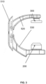
- the X-ray machine 1000 includes a C-shaped arm 500.
- the C-shaped arm 500 includes a connecting arm 510, a first support arm 520, and a second support arm 530, and a combination of the first support arm 520, the second support arm 530, and the connecting arm 510 is C-shaped.
- the detector 300 is arranged on the first support arm 520 and a radiation source 200 is arranged on the second support arm 530, the detector 300 and the radiation source 200 are separately arranged on both sides of a hospital bed.
- the detector 300 is arranged on the upper side of the hospital bed, and the radiation source 200 is arranged on a lower side of the hospital bed.
- the radiation source 200 may be understood as a device capable of emitting X-rays, ⁇ -rays, or electron rays, etc.
- the detector 300 may be understood as a device capable of receiving rays emitted by the radiation source 200, and operations such as a medical examination or treatment may be achieved through a collaboration of the radiation source 200 and the detector 300.
- first support arm 520 and the second support arm 530 are separately movably connected to the connecting arm 510, and the first support arm 520 is used to be capable of moving relative to the connecting arm 510 to move close to or away from the second support arm 530, and the connecting arm 510 moves to drive the first support arm 520 to move close to or away from the second support arm 530.
- the first support arm 520 and the second support arm 530 are separately movably connected to the connecting arm 510 to have at least one of a first movement mode and a second movement mode.
- the first support arm 520 is configured to move relative to the connecting arm 510 and the second support arm 530 to cause the detector 300 to move close to the hospital bed, the first support arm 520 is driven by the connecting arm 510 to follow toward the hospital bed while the second support arm 530 moves relative to the connecting arm 510 to cause the radiation source 200 to move close to the detector 300.
- the first support arm 520 is configured to move relative to the connecting arm 510 and the second support arm 530 to cause the detector 300 to move away from the hospital bed, and the first support arm 520 is driven by the connecting arm 510 to follow away from the hospital bed while the second support arm 530 moves relative to the connecting arm 510 to cause the radiation source 200 to move away from the detector 300.
- the first support arm 520 is configured to move relative to the connecting arm 510 and the second support arm 530 to cause the detector 300 to move close to the hospital bed, and the first support arm 520 reaches a maximum travel relative to the connecting arm 510; or in the second movement mode, the first support arm 520 is configured to move relative to the connecting arm 510 and the second support arm 530 to cause the detector 300 away from the hospital bed, and the first support arm 520 reaches the maximum travel relative to the connecting arm 510.
- the C-shaped arm 500 also includes a first drive device, a second drive device, and a third drive device.
- the first drive device is configured to drive the first support arm 520 to move relative to the connecting arm 510 and the second support arm 530.
- the second drive device is configured to drive the connecting arm 510 to move to drive the first support arm 520 and the second support arm 530 to move.
- the third drive device is configured to drive the second support arm 530 to move relative to the connecting arm 510.
- the C-shaped arm 500 further includes a key assembly and a controller coupled to the key assembly.
- the controller is communicatively connected to the first drive device, the second drive device, and the third drive device, respectively.
- the controller is configured to control the first drive device to drive the first support arm 520 to move, control the second drive device to drive the connecting arm 510 to move to cause the first support arm 520 to follow, and/or control the third drive device to drive the second support arm 530 to move relative to the connecting arm 510 in response to a press of the key assembly.
- the controller in this embodiment may be implemented not only by hardware circuitry such as an ultra-large scale integrated circuit or a gate array, a semiconductor such as a logic chip, a transistor, etc., or a programmable hardware device such as a field programmable gate array, a programmable logic device, etc., but also by software executed using various types of processors, and also by a combination of the above hardware circuitry and software such as firmware.
- hardware circuitry such as an ultra-large scale integrated circuit or a gate array, a semiconductor such as a logic chip, a transistor, etc.
- a programmable hardware device such as a field programmable gate array, a programmable logic device, etc.
- the key assembly includes a first key and/or a second key.
- the controller controls the first drive device, the second drive device, and the third drive device to perform the first movement mode.
- the controller controls the first drive device, the second drive device, and the third drive device to perform the second movement mode.
- the setting of the first key and the second key facilitates operations of the user.
- the first drive device, the second drive device, and the third drive device may include a motor and a transmission device.
- the motor may include a direct drive motor.
- the transmission device may include, but is not limited to, one or a combination of one or more of a worm gear rack transmission, a rack and pinion transmission, a screw and nut transmission, a belt transmission, and a chain transmission.
- the transmission device of the first drive device is connected between the motor of the first drive device and the first support arm 520
- the transmission device of the second drive device is connected between the motor of the second drive device and the connecting arm 510
- the transmission device of the third drive device is connected between the motor of the third drive device and the second support arm 530.
- the structures of the first drive device, the second drive device, and the third drive device may be the same or different.
- the worm gear rack transmission device may be included, or the rack and pinion transmission device may be included.
- the first drive device, the second drive device, and the third drive device may all include a thread nut transmission device.
- the first drive device, the second drive device, and the third drive device may include a hydraulic cylinder, a pneumatic cylinder, etc.
- the second drive device is a robot or a mechanical arm 560 (referring to FIG. 4 ), which drives the connecting arm 510 to drive the first support arm 520 to move relative to the second support arm 530 by the robot or the mechanical arm 560.
- the mechanical arm 560 is rotatably connected to the connecting arm 510, so that a rotation angle of the C-shaped arm 500 may also be adjusted by the mechanical arm 560.
- the first support arm 520 moves along a first path on the connecting arm 510
- the second support arm 530 moves along a second path on the connecting arm 510
- the first path is parallel or co-linear with the second path
- both the first path and the second path extend in a vertical direction.
- the first path and the second path are co-linear, so that a transition between the first support arm 520 moving along the first path and the second support arm 530 moving along the second path is smooth and there is no uncomfortable connection due to a change of the center of gravity.
- a first sliding slot 540 is arranged on the connecting arm 510, a first slider is arranged on the first support arm 520, the first slider is slidably connected to the first sliding slot 540, and a path of the first slider sliding along the first sliding slot 540 is a first path.
- the first sliding slot 540 may also be arranged on the first support arm 520, the first slider is arranged on the connecting arm 510, and as long as the first support arm 520 moves along the first path relative to the connecting arm 510 by a sliding collaboration of the first sliding slot 540 and the first slider.
- a second sliding slot 550 is arranged on the connecting arm 510, a second slider is arranged on the second support arm 530, the second slider is slidably connected to the second sliding slot 550, and a path of the second slider slides along the second sliding slot 550 is a second path.
- the second sliding slot 550 may also be arranged on the second support arm 530, and the second slider is arranged on the connecting arm 510, and as long as the connecting arm 510 and the second support arm 530 move along the second path by a sliding collaboration of the second sliding slot 550 and the second slider.
- the first support arm 520, the connecting arm 510, and the second support arm 530 may be provided with penetration holes for wires or cables used by the devices provided in the first support arm 520 and the second support arm 530 to pass through.
- the setting of the penetration holes may also reduce a weight of the C-shaped arm 500.
- the setting of the penetration holes may also reduce the use amount of the material of the C-shaped arm 500.
- the penetration holes on the first support arm 520, the second support arm 530, and the connecting arm 510 may be set as one, or may also be set as multiple such as 2, 3, 4 or 6, etc. The multiple penetration holes may be connected to each other.
- the number, arrangement, size, and shape of the hollow penetration holes may be set by a person skilled in the art according to practical needs.
- the cross-sectional shapes of the penetration holes may be a circle, a square, a polygon, or an irregular shape, etc. Such variations are still within the scope of protection of the present disclosure.
- reinforcement bars may be arranged in both the first support arm 520 and the second support arm 530.
- the reinforcement bars may further improve a structural strength of the first support arm 520 and the second support arm 530 without increasing a wall thickness of the first support arm 520 and the second support arm 530, so as to avoid deformation of the first support arm 520 and the second support arm 530 under force, so that the first support arm 520 and the second support arm 530 can better support a device set thereon.
- the reinforcement bars may be set in shape of strips or grids, etc. The technical person in the field can specifically design the shape of the reinforcement bars according to the needs, and the present disclosure does not limit this.
- the reinforcement bars may also be arranged in the connecting arm 510.
- the reinforcement bars may be arranged on an outer surface of the first support arm 520, the second support arm 530, and/or the connecting arm 510 of the C-shaped arm 500.
- the purpose of the arrangement of the reinforcement bars is mainly to improve the overall stiffness of the C-shaped arm 500, so the person skilled in the art can also set the reinforcement bars to other positions according to the practical needs, or the number of the reinforcement bars can be reasonably increased or reduced according to the needs.
- the reinforcement bars may also be other reinforcing stiffness structures, such as reinforcing plates, reinforcing ribs, etc. Similar such transformations are still within the scope of protection of the present disclosure.
- the material of the connecting arm 510 may be set as carbon fiber.
- the connecting arm 510, the first support arm 520, and the second support arm 530 may also be spliced by sheet metal parts or castings.
- the adjustable mode of the C-shaped arm 500 in this embodiment can give full play to the structural advantage of the C-shaped arm 500 without changing the operating habits of the operator, and can obtain a larger surgical space and angleforming range, as well as reduce the radiation dose.
- a movement mode increases the movement of the connecting arm 510 and the movement of the second support arm 530 relative to the connecting arm 510
- the operating habits are consistent with those of a physician operating this type of device, i.e., the distance between the radiation source 200, which is located below the hospital bed, and the hospital bed remains essentially constant during the SID adjustment process, and the detector 300 rises or falls relative to the hospital bed from the perspective of the patients' vision, that is, the patients is aware of the SID becoming larger or smaller.
- the X-ray machine 1000 is capable of making the distance between the radiation source 200 and the detector 300 larger or smaller by the aforementioned different manipulation modes during the examination of the patient by setting the C-shaped arm 500 as described above, making it easier for the operator to perform the X-ray examination of the patient. Moreover, the variation range of the SID of the present disclosure is greater than that of the conventional X-ray machine.
- the X-ray machine may include a digital subtraction angiography (DSA) apparatus.
- DSA apparatus is an X-ray machine that combines a conventional angiography and an electronic computer image processing technology, which can make the display of blood vessels and their lesions more clearly and have a high application value.
- An embodiment of the present disclosure also provides an X-ray machine.
- the X-ray machine comprises a frame, a radiation source 200, a detector 300, and a C-shaped arm 500.
- the C-shaped arm 500 includes a connecting arm 510, a first support arm 520, and a second support arm 530.
- the first support arm 520 and the second support arm 530 are both drivable connected to the connecting arm 510.
- the C-shaped arm 500 is arranged on the frame, the detector 300 is arranged on the first support arm 520, and the radiation source 200 is arranged on the second support arm 530.
- the X-ray machine includes at least one of a SID reduction manipulation mode and a SID increase manipulation mode as follows.
- the first support arm 520 is configured to move relative to the connecting arm 510 and the second support arm 530 to cause the detector 300 to move close to a hospital bed, and the first support arm 520 is driven by the connecting arm 510 to follow toward the hospital bed and the second support arm 530 moves relative to the connecting arm 510 to cause the radiation source 200 to move close to the detector 300.
- An embodiment of the present disclosure also provides an X-ray machine.
- the X-ray machine comprises a frame, a radiation source (200), a detector (300), and a C-shaped arm (500).
- the C-shaped arm (500) includes a connecting arm (510), a first support arm (520), and a second support arm (530).
- the first support arm (520) and the second support arm (530) are both drivable connected to the connecting arm (510).
- the C-shaped arm (500) is arranged on the frame, the detector (300) is arranged on the first support arm (520), and the radiation source (200) is arranged on the second support arm (530).
- the X-ray machine includes at least one of a SID reduction manipulation mode and a SID increase manipulation mode as follows.
- a compound movement includes two movements as follows.
- the first support arm 520 is configured to move toward a hospital bed relative to the connecting arm 510
- the second support arm 530 is configured to move toward the hospital bed relative to the connecting arm 510.
- the first support arm 520 moves to the maximum travel of the first support arm 520 away from the hospital bed relative to the connecting arm 510; and/or the second support arm 530 moves to the maximum travel of the second support arm 530 away from the hospital bed relative to the connecting arm 510.
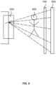
- the X-rays have a certain penetration ability, and the tissue structure of the object 400 to be detected has different density and thickness, so the X-rays have different penetration ability corresponding to different locations of the object 400 to be detected, and the remaining X-rays forms an X-ray image on the detector 300 through an imaging process.
- the primary rays emitted from the radiation source 200 irradiate the object 400 to be detected, many scattered rays in different directions are generated, which blur an image as a whole and affect the contrast of the image.
- the filter grid device 100 is arranged between the object 400 to be detected and the detector 300, and the image becomes very clear after using the filter grid device 100.
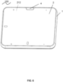
- the filter grid device 100 includes a housing assembly 1 and a filter grid 2 covered with the housing assembly 1, and the filter grid 2 is detachably connected to the housing assembly 1, so as to achieve the replacement of different models or different service life of the filter grid 2.
- a conventional filter grid 2 is connected to the housing assembly 1 by screws, and the operator needs to use a tool such as a screwdriver to disassembly and assembly the screws, which makes the disassemble and assembly of the filter grid 2 and the housing assembly 1 very inconvenient.
- the housing assembly 1 and the filter grid 2 can be unlocked easily and quickly, making the disassembly and assembly of the housing assembly and the filter grid very convenient and saving labor and time.
- the X-ray machine can be quickly disassembled and assembled, saving labor and time.
- the sealing part 22 is capable of sealing the filter grid device 100, which can prevent X-rays from passing backwards through a gap between the filter grid body 21 and the housing assembly 1 and ensure that the X-rays all pass through the filter grid body 21 and the scattered rays are eliminated, thus enabling the image on the detector 300 to achieve maximum clarity.
- the sealing part 22 may be a ring-shaped sponge foam, which can avoid a hard contact between the filter grid 2 and the housing assembly 1, avoid damage to the filter grid 2 and the housing assembly 1 due to a soft texture of the sponge foam, so as to improve the service life of the filter grid 2 and the housing assembly 1.
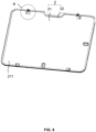
- the operator presses the trigger assembly 4 with one hand and exerts force on the filter grid 2 with the other hand to detach the filter grid 2 from the housing assembly 1, the whole detaching action is done in one go and very smooth, which is convenient for the operator to operate and can effectively improve the disassembly and assembly efficiency of the housing assembly 1 and the filter grid 2.
- the locking assembly 3 in this embodiment is located in an accommodation space formed by the housing assembly 1 and the filter grid 2, and the housing assembly 1 and the filter grid 2 jointly play a role in shielding the locking assembly 3 to avoid a leakage of the locking assembly 3, making the appearance of the filter grid device 100 simple and elegant.
- it can also avoid the problem that the assembly of the housing assembly 1 and the filter grid 2 is not tight due to the operator accidentally touching the locking assembly 3, so that the housing assembly 1 and the filter grid 2 lock tighter, ensuring the normal and safe use of the assembled filter grid device 100.
- the first locking mechanism 31 includes a first locking member 311 and a first reset member 312
- the second locking mechanism 32 includes a second locking member 321
- the first locking member 311 is connected to the housing 11 through the first reset member 312
- the first locking mechanism 31 is connected to the housing 11, and the first reset member 312 drives the second locking member 321 and the first locking member 311 to lock each other.
- the first locking member 311 is provided with a snap hook 3115
- the second locking member 321 is opened with a snap slot 3211
- the first reset member 312 is a spring.
- the spring drives the second locking member 321 to move to achieve the effect that the snap hook 3115 arranged on the first locking member 311 automatically stuck in the snap slot 3211 on the second locking member 321, so as to achieve the automatic locking of the first locking member 311 and the second locking member 321.
- the snap hook 3115 can be effectively prevented from loosening from the snap slot 3211, ensuring a tight locking of the filter grid 2 and the housing assembly 1 and a long time during normal use of the filter grid device 100.
- the snap hook 3115 may also be arranged on the second locking mechanism 32 and the snap slot 321 may be opened on the first locking mechanism 31, which can also achieve the above effect.
- first bevel 421 and the second bevel 3113 are inclined toward a centerline 423 of the trigger assembly 4 from front to back, and the movement of the trigger assembly 4 along the front-to-back direction may be converted into the movement of the first locking member 311 along a left-to-right direction by the setting of the first bevel 421 and the second bevel 3113.
- the housing assembly 1 also includes a first guiding mechanism 12, the first guiding mechanism 12 includes a first guiding member 121 and a first positioning member 122, the first positioning member 122 is fixedly connected to the housing 11, one of the sliding member 42 and the first positioning member 122 is provided with the first guiding member 121, and the other of the sliding member 42 and the first positioning member 122 is provided with a first guiding hole 1221.
- the first guiding member 121 extends into the first guiding hole 1221 and is capable of guiding a sliding process of the trigger assembly 4 relative to the housing 11.
- the first guiding member 121 is a guiding rod fixed to the sliding member 42 extending in a front-back direction, and the guiding hole 1221 is opened on the first positioning member 122, and the guiding rod is inserted in the guiding hole 1221 and is capable of sliding relative to the guiding hole 1221.
- the guiding rod and the guiding hole 1221 may be a clearance fit to ensure a smooth sliding of the guiding rod in the guiding hole 1221, and the guiding rod is capable of guiding the sliding process of the trigger assembly 4 relative to the housing 11.
- the first guiding member 121 also includes a second guiding member 123, the second guiding member 123 includes a screw 1231 and a guiding post 1232, the guiding post 1232 is fixed to the first positioning member 122 by the screw 1231, a second guiding hole 422 is opened on the sliding member 42, and the guiding post 1232 extends in a front-to-back direction and is inserted in the second guiding hole 422.
- the housing assembly 1 also includes a second guiding mechanism 13, and the second guiding mechanism 13 includes a third guiding member 131 connected to the housing 11, and the first locking member 311 is provided with a guiding slot 3114 extending in a left-to-right direction, and a third guiding member 131 is inserted in the guiding slot 3114 and is capable of sliding along the guiding slot 3114, so as to achieve the guiding effect on the sliding of the first locking member 311.
- the housing assembly 1 also includes a third guiding mechanism 14, the third guiding mechanism 14 includes a fourth guiding member 141 and a second positioning member 142, the second positioning member 142 is arranged on one side of the first locking member 311, the second positioning member 142 is provided with a fourth guiding hole 1421, the first locking member 311 extends toward a side of the second positioning member 142 to form a rod-shaped fourth guiding member 141, and the fourth guiding member 141 is inserted in the fourth guiding hole 1421 to guide the sliding process of the first locking member 311 relative to the housing 11.
- the first reset member 312 is a spring, and the spring is sleeved on an outer periphery of the fourth guiding member 141, one end of the spring is against to the second positioning member 142, and the other end of the spring is against to the first locking member 311, so as to ensure that the spring extends or is pressed along the left-to-right direction to avoid the bending of the spring.
- the filter grid device 100 when the filter grid device 100 is mounted on the X-ray machine, the outer surface of the filter grid 2 is often facing downward or the filter grid device 100 is set vertically.
- the filter grid 2 When the operator detaches the filter grid 2 of the filter grid device 100 in the above state, the filter grid 2 is prone to fall due to gravity, and the falling filter grid 2 may hit the operator, thus affecting the operator's personal safety.
- FIGs. 1 In order to solve the above problem, as shown in FIGs.
- the second locking mechanism 32 also includes a second reset member 322 and an anti-release member 323, the anti-release member 323 is connected to and protruded from the second locking member 321 by the second reset member 322, the anti-release member 323 is capable of sliding relative to the second locking member 321, and the housing 11 is provided with an insertion port 1111 for extension of the second locking member 321.
- the anti-release member 323 is capable of being stuck against and limited to a side wall of the insertion port 1111 when the second locking member 321 is unlocked with the first locking mechanism 31, the anti-release member 323 may interfere with the housing 11 so that the filter grid 2 cannot be directly detached from the housing assembly 1, and the operator needs to drag hard to overcome the resistance of the housing 11 to the anti-release member 323.
- the operator can take out the filter grid 2 from the housing 11, which can prevent the filter grid 2 from falling and avoid the filter grid 2 from hitting the operator, thus ensuring the operator's personal safety.
- the disassembly and assembly of the filter grid device 100 is described in connection with FIGs. 7-9 and 11 .
- the second locking member 321 When it is necessary to mount the filter grid 2 to the housing assembly 1, as shown in FIGs. 7-9 , the second locking member 321 is aligned with its corresponding insertion port 1111, the second locking member 321 extends into a back of the housing 11, the second locking member 321 pushes the corresponding first locking member 311 to move outward in the left-to-right direction.
- the snap hook 3115 When the snap hook 3115 is aligned with the snap slot 3211, the first reset member 312 pushes the first locking member 311 to move inward in the left-to -right direction to make the snap hook 3115 snap into the snap slot 321, so that the filter grid 2 may be locked with the housing assembly 1.
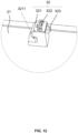
- the filter grid device provided in the third embodiment of the present disclosure has basically the same structure as the filter grid device 100 provided in the second embodiment, the main difference is that, as shown in FIGs. 13 and 14 , the first locking member 311 is also provided with a groove 3111 on the basis of the second embodiment.
- the anti-release member 323 is capable of being clamped and limited in the groove 3111 when the second locking member 321 is unlocked with the first locking member 311, which can further improve the anti-release effect of the filter grid 2 and the housing assembly 1. It is equivalent to that the anti-release member 323 interferes with the groove 3111 and the insertion port 1111 in turn when the second locking member 321 is unlocked with the first locking member 311, making that the anti-release effect of the filter grid 2 is better.
- FIG. 13 is a schematic diagram illustrating structures of the first locking member 311 and the second locking member 321 in a locked state according to the third embodiment of the present disclosure
- FIG. 14 is a schematic diagram illustrating structures of the first locking member 311 and the second locking member 321 in an unlocked state according to the third embodiment of the present disclosure.
- the anti-release member 323 is separated from the groove 3111.
- the anti-release member 323 is clamped and limited in the groove 3111.
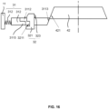
- the filter grid device provided in the fourth embodiment of the present disclosure has essentially the same structure as the filter grid device 100 provided in the second embodiment, the main difference is that, as shown in FIGs. 15 and 16 , the first locking member 311 is provided with an accommodation groove 3112 penetrating along the thickness direction of the filter grid device 100, the second locking mechanism 32 penetrates the accommodation groove 3112, and the anti-release member 323 is capable of being stuck against and limited to the side of the first locking member 311 relatively away from the filter grid 2 when the first locking member 311 is unlocked from the second locking member 321, which can further improve the anti-release effect of the filter grid 2 and the housing assembly 1. It is equivalent to that the anti-release member 323 interferes with the groove 3111 and the insertion port 1111 in turn when the second locking member 321 is unlocked with the first locking member 311, making that the anti-release effect of the filter grid 2 is better.
- FIG. 15 is a schematic diagram illustrating structures of the first locking member 311 and the second locking member 321 in a locked state according to the fourth embodiment of the present disclosure
- FIG. 16 is a schematic diagram illustrating structures of the first locking member 311 and the second locking member 321 in an unlocked state according to the fourth embodiment of the present disclosure.
- the anti-release member 323 is separated from the first locking member 311.
- the anti-release member 323 is stuck against and limited to the side of the first locking member 311 relatively away from the filter grid 2.
Landscapes
- Health & Medical Sciences (AREA)
- Life Sciences & Earth Sciences (AREA)
- Medical Informatics (AREA)
- Engineering & Computer Science (AREA)
- Radiology & Medical Imaging (AREA)
- Biomedical Technology (AREA)
- Biophysics (AREA)
- Nuclear Medicine, Radiotherapy & Molecular Imaging (AREA)
- Optics & Photonics (AREA)
- Pathology (AREA)
- Physics & Mathematics (AREA)
- High Energy & Nuclear Physics (AREA)
- Heart & Thoracic Surgery (AREA)
- Molecular Biology (AREA)
- Surgery (AREA)
- Animal Behavior & Ethology (AREA)
- General Health & Medical Sciences (AREA)
- Public Health (AREA)
- Veterinary Medicine (AREA)
- Apparatus For Radiation Diagnosis (AREA)
Applications Claiming Priority (3)
| Application Number | Priority Date | Filing Date | Title |
|---|---|---|---|
| CN202010801583.3A CN111991014B (zh) | 2020-08-11 | 2020-08-11 | 一种c型臂及x射线机 |
| CN202011025780.7A CN112043298A (zh) | 2020-09-25 | 2020-09-25 | 一种滤线栅装置和医学成像设备 |
| PCT/CN2021/112076 WO2022033522A1 (zh) | 2020-08-11 | 2021-08-11 | X射线机 |
Publications (2)
| Publication Number | Publication Date |
|---|---|
| EP4179974A1 true EP4179974A1 (de) | 2023-05-17 |
| EP4179974A4 EP4179974A4 (de) | 2024-01-17 |
Family
ID=80246969
Family Applications (1)
| Application Number | Title | Priority Date | Filing Date |
|---|---|---|---|
| EP21855573.8A Pending EP4179974A4 (de) | 2020-08-11 | 2021-08-11 | Röntgengerät |
Country Status (3)
| Country | Link |
|---|---|
| US (1) | US12551177B2 (de) |
| EP (1) | EP4179974A4 (de) |
| WO (1) | WO2022033522A1 (de) |
Family Cites Families (20)
| Publication number | Priority date | Publication date | Assignee | Title |
|---|---|---|---|---|
| DE19958864A1 (de) | 1999-12-07 | 2001-06-13 | Philips Corp Intellectual Pty | Röntgeneinrichtung |
| DE102007021770A1 (de) * | 2007-05-09 | 2008-11-20 | Siemens Ag | Medizinisches Diagnose- und/oder Interventionssystem |
| DE102008003815B4 (de) * | 2008-01-10 | 2014-07-31 | Siemens Aktiengesellschaft | Röntgeneinrichtung umfassend einen vorzugsweise an einem Roboterarm um eine Drehachse drehbar gelagerten C-Bogen |
| DE102008032296B4 (de) * | 2008-07-09 | 2010-06-02 | Siemens Aktiengesellschaft | Röntgengerät |
| JP6032876B2 (ja) * | 2011-09-27 | 2016-11-30 | キヤノン株式会社 | 放射線撮影装置およびグリッドユニット |
| CN204106026U (zh) * | 2014-05-06 | 2015-01-21 | 上海西门子医疗器械有限公司 | X射线成像设备及其锁紧装置 |
| CN204108026U (zh) | 2014-06-17 | 2015-01-21 | 浙江跃岭股份有限公司 | 轮毂圆周检测矫形器 |
| CN205458743U (zh) * | 2016-02-29 | 2016-08-17 | 邦盛医疗装备(天津)股份有限公司 | 带栅锁紧机构的平板探测器 |
| CN105832362A (zh) * | 2016-03-16 | 2016-08-10 | 浙江大学 | 多自由度锥束ct成像系统 |
| CN107518907A (zh) | 2016-06-22 | 2017-12-29 | 沈阳东软医疗系统有限公司 | 一种医疗影像装置及其机架 |
| CN108013886B (zh) * | 2016-11-03 | 2021-01-12 | 北京东软医疗设备有限公司 | 一种乳腺机及其滤线栅安装组件 |
| US20190000407A1 (en) * | 2017-06-30 | 2019-01-03 | General Electric Company | Variable distance imaging |
| CN109932374B (zh) * | 2019-04-03 | 2024-01-05 | 天津三英精密仪器股份有限公司 | 一种具备ct和dr双功能成像检测的装置 |
| CN210056051U (zh) | 2019-04-28 | 2020-02-14 | 东软医疗系统股份有限公司 | 滤线栅固定弹出装置及医疗影像设备 |
| CN111227855A (zh) * | 2019-10-22 | 2020-06-05 | 上海联影医疗科技有限公司 | 一种c型臂及x射线机 |
| CN110811655B (zh) * | 2019-11-21 | 2021-08-10 | 上海联影医疗科技股份有限公司 | 一种c型臂及x射线机 |
| CN114209346A (zh) * | 2019-11-21 | 2022-03-22 | 上海联影医疗科技股份有限公司 | 一种c型臂及数字减影血管造影设备 |
| CN110960245B (zh) | 2019-12-30 | 2024-12-27 | 江苏一影医疗设备有限公司 | C型臂ct设备 |
| CN111991014B (zh) * | 2020-08-11 | 2024-08-02 | 上海联影医疗科技股份有限公司 | 一种c型臂及x射线机 |
| CN112043298A (zh) * | 2020-09-25 | 2020-12-08 | 上海联影医疗科技股份有限公司 | 一种滤线栅装置和医学成像设备 |
-
2021
- 2021-08-11 EP EP21855573.8A patent/EP4179974A4/de active Pending
- 2021-08-11 WO PCT/CN2021/112076 patent/WO2022033522A1/zh not_active Ceased
-
2023
- 2023-02-10 US US18/167,825 patent/US12551177B2/en active Active
Also Published As
| Publication number | Publication date |
|---|---|
| EP4179974A4 (de) | 2024-01-17 |
| WO2022033522A1 (zh) | 2022-02-17 |
| US12551177B2 (en) | 2026-02-17 |
| US20230181137A1 (en) | 2023-06-15 |
Similar Documents
| Publication | Publication Date | Title |
|---|---|---|
| US7792245B2 (en) | Breast tomosynthesis system with shifting face shield | |
| EP3320842B1 (de) | Radiographiegerät, verfahren zur steuerung des radiographiegerätes und programm | |
| US10307219B2 (en) | Noninvasive stereotactic assembly | |
| JP2017536167A (ja) | マンモグラフィ/トモシンセシスx線システムのための枢動パドル装置 | |
| JP5371533B2 (ja) | 医療装置 | |
| US12551177B2 (en) | X-ray machines | |
| JP5680311B2 (ja) | Ct撮影用天板及びx線ct装置 | |
| CN114748084A (zh) | 一种影像引导治疗系统用移动c形臂 | |
| JPH10282598A (ja) | 放射線用カセッテキャリア | |
| CN212489932U (zh) | Ct检查装置 | |
| CN113796885A (zh) | 用于口腔cbct的定位固定装置和口腔cbct | |
| US10531849B2 (en) | Radiographic imaging apparatus, radiographic imaging system, radiographic imaging method, and storage medium | |
| CN111991014B (zh) | 一种c型臂及x射线机 | |
| CN111436960A (zh) | 一种ct影像诊断装置 | |
| CN219048546U (zh) | 一种病床dr盒承托结构 | |
| CN216561243U (zh) | 一种放射科辅助阅片装置 | |
| CN212438648U (zh) | 用于口腔cbct的定位装置和口腔cbct | |
| CN210270388U (zh) | 一种便于分析的放射影像片固定装置 | |
| CN215191685U (zh) | 一种放射影像科用头部ct固定调整座 | |
| CN221485533U (zh) | 一种医院辐射环境检测装置 | |
| CN211123497U (zh) | 一种放射影像片固定装置 | |
| CN213282996U (zh) | 用于口腔cbct的定位装置和口腔cbct | |
| CN221599942U (zh) | 一种防护装置 | |
| CN215839133U (zh) | 一种放射检查头部保护装置 | |
| CN214804793U (zh) | 一种放射科用腹部影像诊断装置 |
Legal Events
| Date | Code | Title | Description |
|---|---|---|---|
| STAA | Information on the status of an ep patent application or granted ep patent |
Free format text: STATUS: THE INTERNATIONAL PUBLICATION HAS BEEN MADE |
|
| PUAI | Public reference made under article 153(3) epc to a published international application that has entered the european phase |
Free format text: ORIGINAL CODE: 0009012 |
|
| STAA | Information on the status of an ep patent application or granted ep patent |
Free format text: STATUS: REQUEST FOR EXAMINATION WAS MADE |
|
| 17P | Request for examination filed |
Effective date: 20230213 |
|
| AK | Designated contracting states |
Kind code of ref document: A1 Designated state(s): AL AT BE BG CH CY CZ DE DK EE ES FI FR GB GR HR HU IE IS IT LI LT LU LV MC MK MT NL NO PL PT RO RS SE SI SK SM TR |
|
| RIC1 | Information provided on ipc code assigned before grant |
Ipc: A61B 6/00 20060101AFI20230914BHEP |
|
| DAV | Request for validation of the european patent (deleted) | ||
| DAX | Request for extension of the european patent (deleted) | ||
| A4 | Supplementary search report drawn up and despatched |
Effective date: 20231213 |
|
| RIC1 | Information provided on ipc code assigned before grant |
Ipc: A61B 6/00 20060101AFI20231208BHEP |
|
| STAA | Information on the status of an ep patent application or granted ep patent |
Free format text: STATUS: EXAMINATION IS IN PROGRESS |
|
| 17Q | First examination report despatched |
Effective date: 20241108 |