EP4179978A1 - Imagerie ultrasonore 3d avec adaptation du champ de vision - Google Patents
Imagerie ultrasonore 3d avec adaptation du champ de vision Download PDFInfo
- Publication number
- EP4179978A1 EP4179978A1 EP21290075.7A EP21290075A EP4179978A1 EP 4179978 A1 EP4179978 A1 EP 4179978A1 EP 21290075 A EP21290075 A EP 21290075A EP 4179978 A1 EP4179978 A1 EP 4179978A1
- Authority
- EP
- European Patent Office
- Prior art keywords
- scan
- boundaries
- volumetric region
- fov
- region
- Prior art date
- Legal status (The legal status is an assumption and is not a legal conclusion. Google has not performed a legal analysis and makes no representation as to the accuracy of the status listed.)
- Withdrawn
Links
Images



Classifications
-
- A—HUMAN NECESSITIES
- A61—MEDICAL OR VETERINARY SCIENCE; HYGIENE
- A61B—DIAGNOSIS; SURGERY; IDENTIFICATION
- A61B8/00—Diagnosis using ultrasonic, sonic or infrasonic waves
- A61B8/48—Diagnostic techniques
- A61B8/483—Diagnostic techniques involving the acquisition of a 3D volume of data
-
- A—HUMAN NECESSITIES
- A61—MEDICAL OR VETERINARY SCIENCE; HYGIENE
- A61B—DIAGNOSIS; SURGERY; IDENTIFICATION
- A61B8/00—Diagnosis using ultrasonic, sonic or infrasonic waves
- A61B8/08—Clinical applications
- A61B8/0833—Clinical applications involving detecting or locating foreign bodies or organic structures
- A61B8/085—Clinical applications involving detecting or locating foreign bodies or organic structures for locating body or organic structures, e.g. tumours, calculi, blood vessels, nodules
-
- A—HUMAN NECESSITIES
- A61—MEDICAL OR VETERINARY SCIENCE; HYGIENE
- A61B—DIAGNOSIS; SURGERY; IDENTIFICATION
- A61B8/00—Diagnosis using ultrasonic, sonic or infrasonic waves
- A61B8/46—Ultrasonic, sonic or infrasonic diagnostic devices with special arrangements for interfacing with the operator or the patient
- A61B8/467—Ultrasonic, sonic or infrasonic diagnostic devices with special arrangements for interfacing with the operator or the patient characterised by special input means
- A61B8/469—Ultrasonic, sonic or infrasonic diagnostic devices with special arrangements for interfacing with the operator or the patient characterised by special input means for selection of a region of interest
-
- A—HUMAN NECESSITIES
- A61—MEDICAL OR VETERINARY SCIENCE; HYGIENE
- A61B—DIAGNOSIS; SURGERY; IDENTIFICATION
- A61B8/00—Diagnosis using ultrasonic, sonic or infrasonic waves
- A61B8/54—Control of the diagnostic device
-
- G—PHYSICS
- G01—MEASURING; TESTING
- G01S—RADIO DIRECTION-FINDING; RADIO NAVIGATION; DETERMINING DISTANCE OR VELOCITY BY USE OF RADIO WAVES; LOCATING OR PRESENCE-DETECTING BY USE OF THE REFLECTION OR RERADIATION OF RADIO WAVES; ANALOGOUS ARRANGEMENTS USING OTHER WAVES
- G01S15/00—Systems using the reflection or reradiation of acoustic waves, e.g. sonar systems
- G01S15/88—Sonar systems specially adapted for specific applications
- G01S15/89—Sonar systems specially adapted for specific applications for mapping or imaging
- G01S15/8906—Short-range imaging systems; Acoustic microscope systems using pulse-echo techniques
- G01S15/8909—Short-range imaging systems; Acoustic microscope systems using pulse-echo techniques using a static transducer configuration
- G01S15/8915—Short-range imaging systems; Acoustic microscope systems using pulse-echo techniques using a static transducer configuration using a transducer array
- G01S15/8925—Short-range imaging systems; Acoustic microscope systems using pulse-echo techniques using a static transducer configuration using a transducer array the array being a two-dimensional transducer configuration, i.e. matrix or orthogonal linear arrays
-
- G—PHYSICS
- G01—MEASURING; TESTING
- G01S—RADIO DIRECTION-FINDING; RADIO NAVIGATION; DETERMINING DISTANCE OR VELOCITY BY USE OF RADIO WAVES; LOCATING OR PRESENCE-DETECTING BY USE OF THE REFLECTION OR RERADIATION OF RADIO WAVES; ANALOGOUS ARRANGEMENTS USING OTHER WAVES
- G01S15/00—Systems using the reflection or reradiation of acoustic waves, e.g. sonar systems
- G01S15/88—Sonar systems specially adapted for specific applications
- G01S15/89—Sonar systems specially adapted for specific applications for mapping or imaging
- G01S15/8906—Short-range imaging systems; Acoustic microscope systems using pulse-echo techniques
- G01S15/8993—Three dimensional imaging systems
-
- G—PHYSICS
- G01—MEASURING; TESTING
- G01S—RADIO DIRECTION-FINDING; RADIO NAVIGATION; DETERMINING DISTANCE OR VELOCITY BY USE OF RADIO WAVES; LOCATING OR PRESENCE-DETECTING BY USE OF THE REFLECTION OR RERADIATION OF RADIO WAVES; ANALOGOUS ARRANGEMENTS USING OTHER WAVES
- G01S7/00—Details of systems according to groups G01S13/00, G01S15/00, G01S17/00
- G01S7/52—Details of systems according to groups G01S13/00, G01S15/00, G01S17/00 of systems according to group G01S15/00
- G01S7/52017—Details of systems according to groups G01S13/00, G01S15/00, G01S17/00 of systems according to group G01S15/00 particularly adapted to short-range imaging
- G01S7/52053—Display arrangements
- G01S7/52057—Cathode ray tube displays
- G01S7/5206—Two-dimensional coordinated display of distance and direction; B-scan display
- G01S7/52063—Sector scan display
-
- G—PHYSICS
- G06—COMPUTING OR CALCULATING; COUNTING
- G06T—IMAGE DATA PROCESSING OR GENERATION, IN GENERAL
- G06T7/00—Image analysis
- G06T7/10—Segmentation; Edge detection
- G06T7/12—Edge-based segmentation
-
- G—PHYSICS
- G06—COMPUTING OR CALCULATING; COUNTING
- G06T—IMAGE DATA PROCESSING OR GENERATION, IN GENERAL
- G06T7/00—Image analysis
- G06T7/10—Segmentation; Edge detection
- G06T7/149—Segmentation; Edge detection involving deformable models, e.g. active contour models
-
- G—PHYSICS
- G01—MEASURING; TESTING
- G01S—RADIO DIRECTION-FINDING; RADIO NAVIGATION; DETERMINING DISTANCE OR VELOCITY BY USE OF RADIO WAVES; LOCATING OR PRESENCE-DETECTING BY USE OF THE REFLECTION OR RERADIATION OF RADIO WAVES; ANALOGOUS ARRANGEMENTS USING OTHER WAVES
- G01S15/00—Systems using the reflection or reradiation of acoustic waves, e.g. sonar systems
- G01S15/88—Sonar systems specially adapted for specific applications
- G01S15/89—Sonar systems specially adapted for specific applications for mapping or imaging
- G01S15/8906—Short-range imaging systems; Acoustic microscope systems using pulse-echo techniques
- G01S15/8909—Short-range imaging systems; Acoustic microscope systems using pulse-echo techniques using a static transducer configuration
- G01S15/8915—Short-range imaging systems; Acoustic microscope systems using pulse-echo techniques using a static transducer configuration using a transducer array
-
- G—PHYSICS
- G06—COMPUTING OR CALCULATING; COUNTING
- G06T—IMAGE DATA PROCESSING OR GENERATION, IN GENERAL
- G06T2207/00—Indexing scheme for image analysis or image enhancement
- G06T2207/10—Image acquisition modality
- G06T2207/10132—Ultrasound image
- G06T2207/10136—3D ultrasound image
-
- G—PHYSICS
- G06—COMPUTING OR CALCULATING; COUNTING
- G06T—IMAGE DATA PROCESSING OR GENERATION, IN GENERAL
- G06T2207/00—Indexing scheme for image analysis or image enhancement
- G06T2207/20—Special algorithmic details
- G06T2207/20112—Image segmentation details
- G06T2207/20132—Image cropping
-
- G—PHYSICS
- G06—COMPUTING OR CALCULATING; COUNTING
- G06T—IMAGE DATA PROCESSING OR GENERATION, IN GENERAL
- G06T2207/00—Indexing scheme for image analysis or image enhancement
- G06T2207/30—Subject of image; Context of image processing
- G06T2207/30004—Biomedical image processing
- G06T2207/30048—Heart; Cardiac
Definitions
- the method further comprises acquiring new 3D ultrasound data for the adjusted 3D FOV using the adjusted scanning parameters.
- the scan line depth is controlled by controlling the time duration of the receive phase of the transmit/receive sequence of the relevant transducer(s) used to acquire the relevant scan line.
- the scan parameters are adjusted such as to define a set of scan lines having scan depths set such that each scan line terminates at a point of intersection of the scan line with a distal-most one of the one or more boundaries of the defined volumetric region. Distal-most means furthest along the length of scan line from the ultrasound emission source. All of the scan lines may be set in this way or just a portion. For instance, just the set of scan lines which coincide with the volumetric region may be set in this way.
- the method may further comprise identifying a subset of scan lines which do not intersect with the defined volumetric region, and wherein the scan lines which do not intersect are deactivated when scanning the adjusted FOV. Deactivated means that, in acquiring ultrasound data for the adjusted 3D FOV, these scan lines are not generated/fired.
- all of the scan lines which do not intersect with the volumetric region are deactivated.
- a portion of the non-intersecting scan lines may be retained, for example to capture a pre-defined margin or spacing region around the volumetric region, as will be explained more later.
- the maximum angular widths may be set in dependence upon the boundaries of the identified volumetric region.
- Nearest may mean angularly nearest, i.e. the intersecting line whose scan angle ⁇ , ⁇ is closest to the respective non-intersecting scan line.
- the boundaries of the detected anatomical object-of-interest are simply used as the boundaries of the volumetric region.
- the boundaries of the volumetric region are set so as to match the detected boundaries of the anatomical object of interest.
- the volumetric region is defined to include a spacing around the object of-interest for accommodating movement. Determining the spacing could in some cases be performed automatically based on the reference ultrasound data.
- the reference ultrasound data is 4D ultrasound data (i.e. comprising a series of frames of 3D ultrasound data)
- an extent of said spacing around the boundaries may be determined based on detecting a maximal extent of the object-of-interest boundary across the series of frames.
- the computer-implemented method can be implemented by a processing arrangement, and a processing arrangement adapted to perform the method forms another aspect of this invention.
- control of the transmit/receive sequences of the transducers may be implemented with a timing table that controls the length of each scan line.
- Each line effectively begins with a transmit pulse. A few microseconds after the transmit pulse, the returning echoes start to be received back from the body for that line.
- the scan line effectively terminates when the system ceases to measure or sample the returning echo signals. If the same transducer is used both for transmission and sensing (in alternating duty cycles), then a scan line effectively ends when the transmit pulse for the next line is generated. Therefore, controlling the scan depth of each scan line may in practice comprise configuring the timing table which controls the transmit/receive phase timings for each scan line, and this could be configured by a controller of the system.
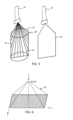
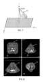
- Fig. 3a illustrates for a single example 2D scan plane 14 j the angle of orientation ⁇ j of the plane along said first dimension ⁇ relative to the z-axis.
- the 3D FOV shown in Fig. 3b is taken to be the first 3D FOV 42 referred to previously, the ultrasound data for which forms the reference ultrasound data referred to previously.
- the first 3D is taken to have a standard FOV geometry (e.g. using a cone or pyramid shaped geometry) which for example spans the maximum possible angular width in both the first ⁇ and second ⁇ directions, and in which each plane 14i has identical shape. In other words it is the full possible FOV. However, this is not essential.
- the first is to identify the subset of the scan lines 16 i which intersect with at least one boundary of the volumetric region 52; identify the point of intersection of each of the identified subset of scan lines with a boundary of the defined volumetric region; and then adjust each respective scan line 16 i depth, d i , such that a terminal point of the scan line coincides with the identified point of intersection for the scan line, and preferably wherein the boundary is a distal-most boundary of the volumetric region along the direction of the scan line.
- Remaining non-intersecting scan lines 16 are deactivated (in other words, when scanning the adjusted FOV to acquire the new ultrasound data, the non-intersecting scan lines are not generated/fired). This results in an adjusted FOV which has boundaries which at least partially match or map onto boundaries of the volumetric region.
- Fig. 5 schematically illustrates the acquisition of a single plane 14 j of data within the adjusted FOV 44.
- the scan depth of the scan lines 16 in the plane have each been individually adjusted so that they terminate at a point of intersection with the outer boundary of the volumetric region.
- the resulting scan plane 14 j has a shape defined by a set of outer boundaries, and wherein a subset of these boundaries coincide with a subset of the boundaries of the volumetric region 52.
- the plane also has further boundaries extending from the ultrasound source, and span the area of scan line propagation toward the volumetric region from the ultrasound source.
- the total resulting adjusted 3D FOV 44 will likewise comprise a set of outer boundaries, a subset of which coincide with the boundaries of the volumetric region 52.
- the distal-most boundaries of the volumetric region along directions of ultrasound propagation from the ultrasound source will coincide with distal-most boundaries of the adjusted 3D FOV along said directions of propagation.
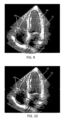
- the volumetric region 52 may be defined based on the result of anatomical segmentation applied to the reference ultrasound data.
- the volumetric region may simply be defined as the volume which is occupied by a detected anatomical feature or object, i.e. the boundaries of the volumetric region are set to match the boundaries of the detected anatomical object.
- the volumetric region may be set as a shape template which is sized and positioned to encompass the volume occupied by the detected anatomical object. The latter may be computationally more efficient, since it may allow for some of the scan line depth calculations to be performed partially in advance for instance.
- Neural networks for generic 2D or 3D image segmentation are known in the art.
- a 3D volumetric region which contains within it all heart structures for which imaging data is desired, and optionally also a further margin to cover heart motion over the cardiac cycle, i.e. heartbeat to heartbeat.
- Such margins can also ensure that the target structures are imaged with some spatial anatomical context.
- the total received signal, used to form an associated line of the final ultrasound image will be a sum of the voltage signals measured by the transducer elements of the given sub-aperture during the receive period.
- the resulting line signals following the beamforming process below, are typically referred to as radio frequency (RF) data.
- RF data radio frequency
- Each line signal (RF data set) generated by the various sub-apertures then undergoes additional processing to generate the lines of the final ultrasound image.
- the change in amplitude of the line signal with time will contribute to the change in brightness of the ultrasound image with depth, wherein a high amplitude peak will correspond to a bright pixel (or collection of pixels) in the final image.
- a peak appearing near the beginning of the line signal will represent an echo from a shallow structure, whereas peaks appearing progressively later in the line signal will represent echoes from structures at increasing depths within the subject.
- analog ultrasound signals typically referred to as channel data
- channel data For each transducer element of the transducer array, analog ultrasound signals, typically referred to as channel data, enter the system by way of the reception channel.
- partially beamformed signals are produced from the channel data by the microbeamformer 112 and are then passed to a main receive beamformer 120 where the partially beamformed signals from individual patches of transducers are combined into a fully beamformed signal, referred to as radio frequency (RF) data.
- RF radio frequency
- the beamforming performed at each stage may be carried out as described above, or may include additional functions.
- the main beamformer 120 may have 128 channels, each of which receives a partially beamformed signal from a patch of dozens or hundreds of transducer elements. In this way, the signals received by thousands of transducers of a transducer array can contribute efficiently to a single beamformed signal.
- the beamformed reception signals are coupled to a signal processor 122.
- the signal processor 122 can process the received echo signals in various ways, such as: band-pass filtering; decimation; I and Q component separation; and harmonic signal separation, which acts to separate linear and nonlinear signals so as to enable the identification of nonlinear (higher harmonics of the fundamental frequency) echo signals returned from tissue and micro-bubbles.
- the signal processor may also perform additional signal enhancement such as speckle reduction, signal compounding, and noise elimination.
- the band-pass filter in the signal processor can be a tracking filter, with its pass band sliding from a higher frequency band to a lower frequency band as echo signals are received from increasing depths, thereby rejecting noise at higher frequencies from greater depths that is typically devoid of anatomical information.
- the transmission and reception channels use the same transducer array 106 which has a fixed frequency band. However, the bandwidth that the transmission pulses occupy can vary depending on the transmission beamforming used.
- the reception channel can capture the whole transducer bandwidth (which is the classic approach) or, by using bandpass processing, it can extract only the bandwidth that contains the desired information (e.g. the harmonics of the main harmonic).
- the one or more processors of the processing arrangement can be implemented in numerous ways, with software and/or hardware, to perform the various functions required.
- a processor typically employs one or more microprocessors that may be programmed using software (e.g., microcode) to perform the required functions.
- the processor may be implemented as a combination of dedicated hardware to perform some functions and one or more programmed microprocessors and associated circuitry to perform other functions.
- circuitry examples include, but are not limited to, conventional microprocessors, application specific integrated circuits (ASICs), and field-programmable gate arrays (FPGAs).
- ASICs application specific integrated circuits
- FPGAs field-programmable gate arrays
Landscapes
- Engineering & Computer Science (AREA)
- Health & Medical Sciences (AREA)
- Life Sciences & Earth Sciences (AREA)
- Physics & Mathematics (AREA)
- Remote Sensing (AREA)
- Radar, Positioning & Navigation (AREA)
- General Physics & Mathematics (AREA)
- Surgery (AREA)
- Veterinary Medicine (AREA)
- Heart & Thoracic Surgery (AREA)
- Medical Informatics (AREA)
- Molecular Biology (AREA)
- Radiology & Medical Imaging (AREA)
- Animal Behavior & Ethology (AREA)
- General Health & Medical Sciences (AREA)
- Public Health (AREA)
- Biomedical Technology (AREA)
- Biophysics (AREA)
- Nuclear Medicine, Radiotherapy & Molecular Imaging (AREA)
- Pathology (AREA)
- Acoustics & Sound (AREA)
- Theoretical Computer Science (AREA)
- Computer Vision & Pattern Recognition (AREA)
- Computer Networks & Wireless Communication (AREA)
- Software Systems (AREA)
- Vascular Medicine (AREA)
- Ultra Sonic Daignosis Equipment (AREA)
Priority Applications (6)
| Application Number | Priority Date | Filing Date | Title |
|---|---|---|---|
| EP21290075.7A EP4179978A1 (fr) | 2021-11-16 | 2021-11-16 | Imagerie ultrasonore 3d avec adaptation du champ de vision |
| PCT/EP2022/081031 WO2023088715A1 (fr) | 2021-11-16 | 2022-11-08 | Imagerie ultrasonore 3d à adaptation de champ de vue |
| EP22814333.5A EP4432926B1 (fr) | 2021-11-16 | 2022-11-08 | Imagerie ultrasonore 3d avec adaptation du champ de vision |
| JP2024521325A JP2024543308A (ja) | 2021-11-16 | 2022-11-08 | Fov適応を用いた3d超音波画像 |
| CN202280076314.2A CN118251180A (zh) | 2021-11-16 | 2022-11-08 | 具有视场调整的3d超声成像 |
| US18/708,352 US12564382B2 (en) | 2021-11-16 | 2022-11-08 | 3D ultrasound imaging with FOV adaptation |
Applications Claiming Priority (1)
| Application Number | Priority Date | Filing Date | Title |
|---|---|---|---|
| EP21290075.7A EP4179978A1 (fr) | 2021-11-16 | 2021-11-16 | Imagerie ultrasonore 3d avec adaptation du champ de vision |
Publications (1)
| Publication Number | Publication Date |
|---|---|
| EP4179978A1 true EP4179978A1 (fr) | 2023-05-17 |
Family
ID=78916635
Family Applications (2)
| Application Number | Title | Priority Date | Filing Date |
|---|---|---|---|
| EP21290075.7A Withdrawn EP4179978A1 (fr) | 2021-11-16 | 2021-11-16 | Imagerie ultrasonore 3d avec adaptation du champ de vision |
| EP22814333.5A Active EP4432926B1 (fr) | 2021-11-16 | 2022-11-08 | Imagerie ultrasonore 3d avec adaptation du champ de vision |
Family Applications After (1)
| Application Number | Title | Priority Date | Filing Date |
|---|---|---|---|
| EP22814333.5A Active EP4432926B1 (fr) | 2021-11-16 | 2022-11-08 | Imagerie ultrasonore 3d avec adaptation du champ de vision |
Country Status (5)
| Country | Link |
|---|---|
| US (1) | US12564382B2 (fr) |
| EP (2) | EP4179978A1 (fr) |
| JP (1) | JP2024543308A (fr) |
| CN (1) | CN118251180A (fr) |
| WO (1) | WO2023088715A1 (fr) |
Cited By (2)
| Publication number | Priority date | Publication date | Assignee | Title |
|---|---|---|---|---|
| CN117804381A (zh) * | 2024-03-01 | 2024-04-02 | 成都信息工程大学 | 一种基于相机阵列聚焦结构光对物体三维重建方法 |
| US20250281158A1 (en) * | 2024-03-06 | 2025-09-11 | Biosense Webster (Israel) Ltd. | Systems and methods for location-based medical rendering |
Citations (10)
| Publication number | Priority date | Publication date | Assignee | Title |
|---|---|---|---|---|
| US5997479A (en) | 1998-05-28 | 1999-12-07 | Hewlett-Packard Company | Phased array acoustic systems with intra-group processors |
| US6013032A (en) | 1998-03-13 | 2000-01-11 | Hewlett-Packard Company | Beamforming methods and apparatus for three-dimensional ultrasound imaging using two-dimensional transducer array |
| US6283919B1 (en) | 1996-11-26 | 2001-09-04 | Atl Ultrasound | Ultrasonic diagnostic imaging with blended tissue harmonic signals |
| US6443896B1 (en) | 2000-08-17 | 2002-09-03 | Koninklijke Philips Electronics N.V. | Method for creating multiplanar ultrasonic images of a three dimensional object |
| US6458083B1 (en) | 1996-11-26 | 2002-10-01 | Koninklijke Philips Electronics N.V. | Ultrasonic harmonic imaging with adaptive image formation |
| US6530885B1 (en) | 2000-03-17 | 2003-03-11 | Atl Ultrasound, Inc. | Spatially compounded three dimensional ultrasonic images |
| US6623432B2 (en) | 2000-08-24 | 2003-09-23 | Koninklijke Philips Electronics N.V. | Ultrasonic diagnostic imaging transducer with hexagonal patches |
| US20160262720A1 (en) * | 2015-03-12 | 2016-09-15 | Siemens Medical Solutions Usa, Inc. | Continuously oriented enhanced ultrasound imaging of a sub-volume |
| EP3649959A1 (fr) * | 2018-11-06 | 2020-05-13 | Koninklijke Philips N.V. | Unité de contrôle à ultrasons |
| EP3711673A1 (fr) * | 2019-03-18 | 2020-09-23 | Koninklijke Philips N.V. | Procédés et systèmes permettant de régler le champ de vision d'une sonde à ultrasons |
Family Cites Families (12)
| Publication number | Priority date | Publication date | Assignee | Title |
|---|---|---|---|---|
| US6056691A (en) | 1998-06-24 | 2000-05-02 | Ecton, Inc. | System for collecting ultrasound imaging data at an adjustable collection image frame rate |
| US6984211B2 (en) * | 2003-01-03 | 2006-01-10 | Mayo Foundation For Medical Education And Research | Detection of tumor halos in ultrasound images |
| EP2155068B1 (fr) * | 2007-05-16 | 2016-12-21 | Verathon, Inc. | Système et procédé pour une imagerie harmonique ultrasonore |
| KR101126851B1 (ko) | 2008-08-27 | 2012-03-23 | 삼성메디슨 주식회사 | 적응적 컬러 도플러 수행 방법 및 그를 위한 초음파 진단 시스템 |
| CA2640462C (fr) * | 2008-10-03 | 2016-06-28 | Zetec, Inc. | Systeme et methode de controle par ultrasons |
| KR101097607B1 (ko) | 2010-01-12 | 2011-12-22 | 삼성메디슨 주식회사 | 스캔 각도, 스캔 깊이 및 스캔 속도를 설정하는 초음파 시스템 및 방법 |
| WO2011148275A1 (fr) | 2010-05-26 | 2011-12-01 | Koninklijke Philips Electronics N.V. | Imagerie diagnostique échographique 3d à fréquence volumique élevée du cœur |
| CN106821416A (zh) | 2016-12-29 | 2017-06-13 | 飞依诺科技(苏州)有限公司 | 一种扫描线密度调节方法及装置 |
| EP3469993A1 (fr) | 2017-10-16 | 2019-04-17 | Koninklijke Philips N.V. | Système et procédé d'imagerie par ultrasons |
| US11583244B2 (en) * | 2019-10-04 | 2023-02-21 | GE Precision Healthcare LLC | System and methods for tracking anatomical features in ultrasound images |
| US12205293B2 (en) * | 2021-12-09 | 2025-01-21 | GE Precision Healthcare LLC | System and methods for segmenting images |
| US20230267618A1 (en) * | 2022-02-18 | 2023-08-24 | GE Precision Healthcare LLC | Systems and methods for automated ultrasound examination |
-
2021
- 2021-11-16 EP EP21290075.7A patent/EP4179978A1/fr not_active Withdrawn
-
2022
- 2022-11-08 JP JP2024521325A patent/JP2024543308A/ja active Pending
- 2022-11-08 US US18/708,352 patent/US12564382B2/en active Active
- 2022-11-08 EP EP22814333.5A patent/EP4432926B1/fr active Active
- 2022-11-08 WO PCT/EP2022/081031 patent/WO2023088715A1/fr not_active Ceased
- 2022-11-08 CN CN202280076314.2A patent/CN118251180A/zh active Pending
Patent Citations (10)
| Publication number | Priority date | Publication date | Assignee | Title |
|---|---|---|---|---|
| US6283919B1 (en) | 1996-11-26 | 2001-09-04 | Atl Ultrasound | Ultrasonic diagnostic imaging with blended tissue harmonic signals |
| US6458083B1 (en) | 1996-11-26 | 2002-10-01 | Koninklijke Philips Electronics N.V. | Ultrasonic harmonic imaging with adaptive image formation |
| US6013032A (en) | 1998-03-13 | 2000-01-11 | Hewlett-Packard Company | Beamforming methods and apparatus for three-dimensional ultrasound imaging using two-dimensional transducer array |
| US5997479A (en) | 1998-05-28 | 1999-12-07 | Hewlett-Packard Company | Phased array acoustic systems with intra-group processors |
| US6530885B1 (en) | 2000-03-17 | 2003-03-11 | Atl Ultrasound, Inc. | Spatially compounded three dimensional ultrasonic images |
| US6443896B1 (en) | 2000-08-17 | 2002-09-03 | Koninklijke Philips Electronics N.V. | Method for creating multiplanar ultrasonic images of a three dimensional object |
| US6623432B2 (en) | 2000-08-24 | 2003-09-23 | Koninklijke Philips Electronics N.V. | Ultrasonic diagnostic imaging transducer with hexagonal patches |
| US20160262720A1 (en) * | 2015-03-12 | 2016-09-15 | Siemens Medical Solutions Usa, Inc. | Continuously oriented enhanced ultrasound imaging of a sub-volume |
| EP3649959A1 (fr) * | 2018-11-06 | 2020-05-13 | Koninklijke Philips N.V. | Unité de contrôle à ultrasons |
| EP3711673A1 (fr) * | 2019-03-18 | 2020-09-23 | Koninklijke Philips N.V. | Procédés et systèmes permettant de régler le champ de vision d'une sonde à ultrasons |
Non-Patent Citations (2)
| Title |
|---|
| OLIVIER ECABERT ET AL.: "Automatic model-based segmentation of the heart in CT images", IEEE TRANS. MEDICAL IMAGING, vol. 27, no. 9, September 2008 (2008-09-01), pages 1189 - 1201 |
| OLIVIER ECABERT ET AL.: "Segmentation of the heart and great vessels in CT images using a model-based adaptation engine", MEDICAL IMAGE ANALYSIS, vol. 15, no. 6, 2011, pages 863 - 876, XP028312871, DOI: 10.1016/j.media.2011.06.004 |
Cited By (3)
| Publication number | Priority date | Publication date | Assignee | Title |
|---|---|---|---|---|
| CN117804381A (zh) * | 2024-03-01 | 2024-04-02 | 成都信息工程大学 | 一种基于相机阵列聚焦结构光对物体三维重建方法 |
| CN117804381B (zh) * | 2024-03-01 | 2024-05-10 | 成都信息工程大学 | 一种基于相机阵列聚焦结构光对物体三维重建方法 |
| US20250281158A1 (en) * | 2024-03-06 | 2025-09-11 | Biosense Webster (Israel) Ltd. | Systems and methods for location-based medical rendering |
Also Published As
| Publication number | Publication date |
|---|---|
| EP4432926B1 (fr) | 2025-08-06 |
| US12564382B2 (en) | 2026-03-03 |
| US20240415493A1 (en) | 2024-12-19 |
| EP4432926A1 (fr) | 2024-09-25 |
| WO2023088715A1 (fr) | 2023-05-25 |
| JP2024543308A (ja) | 2024-11-21 |
| CN118251180A (zh) | 2024-06-25 |
Similar Documents
| Publication | Publication Date | Title |
|---|---|---|
| JP7008880B2 (ja) | 誘導超音波データ収集のためのシステム及び方法 | |
| JP7605268B2 (ja) | 超音波画像による脂肪層の識別 | |
| EP3866698B1 (fr) | Systèmes et procédés pour guider l'acquisition d'une image ultrasonore | |
| EP3934539B1 (fr) | Procédés et systèmes d'acquisition d'images ultrasonores 3d composites | |
| US20230301631A1 (en) | Optimal scan plane selection for organ viewing | |
| EP4408294B1 (fr) | Système et procédé de segmentation d'une structure anatomique | |
| EP4432926B1 (fr) | Imagerie ultrasonore 3d avec adaptation du champ de vision | |
| JP7261870B2 (ja) | 超音波画像内のツールを追跡するためのシステム及び方法 | |
| EP3849424B1 (fr) | Suivi d'un outil dans une image ultrasonore | |
| EP3900846A1 (fr) | Sonde d'imagerie acoustique comportant un élément de transducteur | |
| EP4472518B1 (fr) | Procédés et systèmes permettant d'effectuer des estimations de poids des foetus | |
| EP4159139A1 (fr) | Système et procédé de segmentation d'une structure anatomique | |
| EP4262564B1 (fr) | Détection de limite dans les données ultrasonores | |
| EP4014883A1 (fr) | Détection de limite dans les données ultrasonores |
Legal Events
| Date | Code | Title | Description |
|---|---|---|---|
| STAA | Information on the status of an ep patent application or granted ep patent |
Free format text: STATUS: UNKNOWN |
|
| PUAI | Public reference made under article 153(3) epc to a published international application that has entered the european phase |
Free format text: ORIGINAL CODE: 0009012 |
|
| STAA | Information on the status of an ep patent application or granted ep patent |
Free format text: STATUS: THE APPLICATION HAS BEEN PUBLISHED |
|
| AK | Designated contracting states |
Kind code of ref document: A1 Designated state(s): AL AT BE BG CH CY CZ DE DK EE ES FI FR GB GR HR HU IE IS IT LI LT LU LV MC MK MT NL NO PL PT RO RS SE SI SK SM TR |
|
| STAA | Information on the status of an ep patent application or granted ep patent |
Free format text: STATUS: THE APPLICATION IS DEEMED TO BE WITHDRAWN |
|
| 18D | Application deemed to be withdrawn |
Effective date: 20231118 |