EP4180246B1 - Piston dérouleur - Google Patents
Piston dérouleur Download PDFInfo
- Publication number
- EP4180246B1 EP4180246B1 EP22203465.4A EP22203465A EP4180246B1 EP 4180246 B1 EP4180246 B1 EP 4180246B1 EP 22203465 A EP22203465 A EP 22203465A EP 4180246 B1 EP4180246 B1 EP 4180246B1
- Authority
- EP
- European Patent Office
- Prior art keywords
- piston
- rolling
- rolling piston
- air
- rib
- Prior art date
- Legal status (The legal status is an assumption and is not a legal conclusion. Google has not performed a legal analysis and makes no representation as to the accuracy of the status listed.)
- Active
Links
Images


Classifications
-
- B—PERFORMING OPERATIONS; TRANSPORTING
- B60—VEHICLES IN GENERAL
- B60G—VEHICLE SUSPENSION ARRANGEMENTS
- B60G11/00—Resilient suspensions characterised by arrangement, location or kind of springs
- B60G11/26—Resilient suspensions characterised by arrangement, location or kind of springs having fluid springs only, e.g. hydropneumatic springs
- B60G11/27—Resilient suspensions characterised by arrangement, location or kind of springs having fluid springs only, e.g. hydropneumatic springs wherein the fluid is a gas
-
- B—PERFORMING OPERATIONS; TRANSPORTING
- B60—VEHICLES IN GENERAL
- B60G—VEHICLE SUSPENSION ARRANGEMENTS
- B60G11/00—Resilient suspensions characterised by arrangement, location or kind of springs
- B60G11/26—Resilient suspensions characterised by arrangement, location or kind of springs having fluid springs only, e.g. hydropneumatic springs
- B60G11/28—Resilient suspensions characterised by arrangement, location or kind of springs having fluid springs only, e.g. hydropneumatic springs characterised by means specially adapted for attaching the spring to axle or sprung part of the vehicle
-
- F—MECHANICAL ENGINEERING; LIGHTING; HEATING; WEAPONS; BLASTING
- F16—ENGINEERING ELEMENTS AND UNITS; GENERAL MEASURES FOR PRODUCING AND MAINTAINING EFFECTIVE FUNCTIONING OF MACHINES OR INSTALLATIONS; THERMAL INSULATION IN GENERAL
- F16F—SPRINGS; SHOCK-ABSORBERS; MEANS FOR DAMPING VIBRATION
- F16F9/00—Springs, vibration-dampers, shock-absorbers, or similarly-constructed movement-dampers using a fluid or the equivalent as damping medium
- F16F9/02—Springs, vibration-dampers, shock-absorbers, or similarly-constructed movement-dampers using a fluid or the equivalent as damping medium using gas only or vacuum
- F16F9/04—Springs, vibration-dampers, shock-absorbers, or similarly-constructed movement-dampers using a fluid or the equivalent as damping medium using gas only or vacuum in a chamber with a flexible wall
- F16F9/05—Springs, vibration-dampers, shock-absorbers, or similarly-constructed movement-dampers using a fluid or the equivalent as damping medium using gas only or vacuum in a chamber with a flexible wall the flexible wall being of the rolling diaphragm type
- F16F9/057—Springs, vibration-dampers, shock-absorbers, or similarly-constructed movement-dampers using a fluid or the equivalent as damping medium using gas only or vacuum in a chamber with a flexible wall the flexible wall being of the rolling diaphragm type characterised by the piston
-
- B—PERFORMING OPERATIONS; TRANSPORTING
- B60—VEHICLES IN GENERAL
- B60G—VEHICLE SUSPENSION ARRANGEMENTS
- B60G2202/00—Indexing codes relating to the type of spring, damper or actuator
- B60G2202/10—Type of spring
- B60G2202/15—Fluid spring
- B60G2202/152—Pneumatic spring
-
- B—PERFORMING OPERATIONS; TRANSPORTING
- B60—VEHICLES IN GENERAL
- B60G—VEHICLE SUSPENSION ARRANGEMENTS
- B60G2204/00—Indexing codes related to suspensions per se or to auxiliary parts
- B60G2204/10—Mounting of suspension elements
- B60G2204/12—Mounting of springs or dampers
- B60G2204/126—Mounting of pneumatic springs
-
- B—PERFORMING OPERATIONS; TRANSPORTING
- B60—VEHICLES IN GENERAL
- B60G—VEHICLE SUSPENSION ARRANGEMENTS
- B60G2206/00—Indexing codes related to the manufacturing of suspensions: constructional features, the materials used, procedures or tools
- B60G2206/01—Constructional features of suspension elements, e.g. arms, dampers, springs
- B60G2206/014—Constructional features of suspension elements, e.g. arms, dampers, springs with reinforcing nerves or branches
-
- B—PERFORMING OPERATIONS; TRANSPORTING
- B60—VEHICLES IN GENERAL
- B60G—VEHICLE SUSPENSION ARRANGEMENTS
- B60G2206/00—Indexing codes related to the manufacturing of suspensions: constructional features, the materials used, procedures or tools
- B60G2206/01—Constructional features of suspension elements, e.g. arms, dampers, springs
- B60G2206/40—Constructional features of dampers and/or springs
- B60G2206/42—Springs
- B60G2206/424—Plunger or top retainer construction for bellows or rolling lobe type air springs
-
- B—PERFORMING OPERATIONS; TRANSPORTING
- B60—VEHICLES IN GENERAL
- B60G—VEHICLE SUSPENSION ARRANGEMENTS
- B60G2206/00—Indexing codes related to the manufacturing of suspensions: constructional features, the materials used, procedures or tools
- B60G2206/01—Constructional features of suspension elements, e.g. arms, dampers, springs
- B60G2206/70—Materials used in suspensions
- B60G2206/71—Light weight materials
-
- F—MECHANICAL ENGINEERING; LIGHTING; HEATING; WEAPONS; BLASTING
- F16—ENGINEERING ELEMENTS AND UNITS; GENERAL MEASURES FOR PRODUCING AND MAINTAINING EFFECTIVE FUNCTIONING OF MACHINES OR INSTALLATIONS; THERMAL INSULATION IN GENERAL
- F16F—SPRINGS; SHOCK-ABSORBERS; MEANS FOR DAMPING VIBRATION
- F16F9/00—Springs, vibration-dampers, shock-absorbers, or similarly-constructed movement-dampers using a fluid or the equivalent as damping medium
- F16F9/32—Details
- F16F9/54—Arrangements for attachment
Definitions
- the invention relates to a rolling piston of an air spring system according to the preamble of claim 1.
- a rolling piston is known from US 2010/0127438 A1 known.
- Air springs of this type are well known in the art and are used in particular in the suspension of vehicles, for example in the chassis of commercial or rail vehicles, but also for the suspension of driver's seats in commercial vehicles or for the suspension of cabins or passenger compartments.
- chassis Driver's cabs opposite the vehicle frame, also called chassis.
- the air springs are always connected to an air supply, usually via hoses and/or air lines.
- the air supply is usually via a pressure reservoir in the vehicle, which is filled using a compressor and then provides the air supply for the individual suspensions via a control system.
- the air spring control is often integrated into the rest of the vehicle control system.
- Air springs, especially rolling bellows air springs usually have an upper connection part and are thus attached to the vehicle frame, for example.
- the upper connection part is therefore part of the air spring system and must securely fix the air spring bellows and seal it airtight.
- the upper connection part can also include an air connection to supply air to the air spring.
- the so-called rolling piston serves as the lower connection part, which is connected on the chassis side, for example to the axle to be sprung.
- the rolling piston is movable relative to the upper connection part as a result of the wheel's compression movement, so that the air spring bellows rolls along the outer circumference of the rolling piston, forming a rolling fold.
- the upper connection part, rolling piston and air spring bellows form an airtight cavity that is closed off from the environment. This is comparable to the use of air springs for the suspension of driver seats in commercial vehicles or for the suspension of cabins.
- the force is introduced from the vehicle frame via the upper connection component of the air spring in the rolling piston.
- the rolling piston transfers the entire force to the axle to be sprung. The force can also be transferred in the opposite direction.
- the EN 10 2017 222 128 A1 discloses an air spring with a connection part having an air connection, wherein the air connection is designed as an air connection component embedded in the plastic in a form-fitting and material-locking manner.
- the EN 10 2011 050 103 A1 discloses a rolling piston for an air spring bellows made of plastic.
- the rolling piston comprises a support for a stop buffer acting essentially in the axial direction of the air spring, which consists of two interacting parts.
- the tubular interior of the support parts is stiffened with rib-like stiffening elements.
- the rolling piston of the EN 10 2011 050 103 A1 includes a support and an additional stiffening element on the piston bottom for improved absorption of transverse forces.
- the air spring not all components, such as the support, are required to fulfil the basic technical function of a rolling piston.
- the support as an additional component leads to additional weight and/or requires additional installation space, both of which are actually not desired, as already mentioned.
- a further disadvantage is that a high number of components increases the complexity and/or costs of manufacturing.
- the contact surface of the piston crown on the associated components is not formed over the entire surface of the piston crown.
- a small contact surface can result in high point loads on the piston crown. This can lead to an uneven distribution of mechanical stress within the rolling piston.
- the wall thickness of the rolling piston must be designed to be sufficiently large in order to be able to withstand the mechanical stresses described. The disadvantage of this is that it requires a lot of material, which results in a high component weight and high component costs.
- the invention is based on the object of providing a rolling piston in which, for a given load, a more even distribution of stress prevails on the components connected to the rolling piston, even with a small contact surface of the piston head.
- the rolling piston should be provided with the minimum number of components required for its function within an air spring system.
- the overarching task is therefore to provide a rolling piston with the lowest possible material usage and the lowest possible weight at a reasonable cost.
- Claim 12 relates to an air spring system with a rolling piston according to the invention.
- Claim 13 relates to a motor vehicle, in particular a truck, with an air spring according to the invention.
- the rolling piston of an air spring system comprises a pot-shaped piston lower part, wherein the piston lower part has a piston bottom with a bearing surface and a rotationally symmetrical piston wall. Furthermore, the Rolling piston: a piston top part that is hermetically connected to the piston bottom part and connected to the piston wall and designed as a cover, wherein several rib-like stiffening elements are arranged between the piston bottom and the piston wall in a rotationally symmetrical manner in the radial direction, in particular in a radial manner to a longitudinal axis that runs normal to the piston bottom.
- the rib-like stiffening elements have a first side surface and a second side surface, wherein the piston top part has a flange and a frame. The frame protrudes axially from the flange by a predetermined amount in the direction away from the piston bottom.
- the invention is characterized in that the piston crown has a circumferential bead which is arranged rotationally symmetrically in the radial direction and has a predetermined radius.
- the rolling piston is made up of two parts, namely a lower piston part and an upper piston part.
- the lower piston part has a piston head and a piston wall.
- the piston wall is supported on its inner diameter by rib-like stiffening elements on the piston head, thus giving the lower piston part greater stability.
- the rib-like stiffening elements can achieve comparable stiffness while using less material and thus reducing weight.
- the piston head has a support surface against which a component connected to the piston head can lie flat.
- the rolling piston can be connected to the chassis, for example to an axle that is to be sprung.
- the spring forces that occur are essentially introduced in the axial direction of the rolling piston through the components that are to be cushioned against each other and are connected to the rolling piston via the upper piston part and are passed through the rolling piston into the piston head, or vice versa.
- the piston head must therefore be particularly stable and resilient.
- the piston crown may elastically deform in the axial direction due to high local mechanical stresses in the area of the contact surface Increased shear stresses can occur in the piston crown due to local elastic deformation.
- the rotationally symmetrical bead according to the invention forms a wave-shaped course of the piston crown when viewed in the cross section of the rolling piston.
- the bead can be perceived as a concave contour formed by a radius and curved inwards.
- the piston crown can be individually adapted to the various stress states.
- the rotationally symmetrical bead allows the previously described shear stresses to be converted into compressive stresses in a particularly advantageous manner.
- the compressive stresses follow the contour of the piston crown, in other words they lie in the plane of the piston crown, which allows for an optimal stress profile and a more even stress distribution within the piston crown.
- the solution according to the invention advantageously makes it possible to ensure a uniform distribution of stress in the piston crown, even with a small contact surface of the piston crown, so that local stress peaks can be avoided. This can prevent local overloading of the rolling piston.
- the piston crown can be manufactured with a thinner wall, which can reduce the amount of material used. A lower use of material can in turn lead to cost savings in the manufacture of the rolling piston.
- the rolling piston can be made particularly light due to the low use of material. By saving the weight of individual components, the payload of commercial vehicles can be increased, for example, which can generate economic advantages for fleet operators or freight forwarders.
- the bead limits the support surface in the radial direction.
- the shear stress can be diverted into compressive stress in the area of the support surface where the shear stresses occur.
- the stress distribution in the piston crown can be further optimized by a defined position of the bead at the edge of the contact surface of a component connected to the piston crown.
- a transition element connects the piston crown to the first side surface and the second side surface of the rib-like stiffening elements.
- the rib-like stiffening elements are connected to the piston head via the first side surface and the second side surface.
- the connection is made via a transition element, whereby the transition element can be made of the same material as the piston head and the rib-like stiffening elements.
- the transition element can be convex or shaped as a slope.
- the transition element can open into a thickened region of the rib-like stiffening element.
- transition element allows the mechanical stresses to be advantageously evenly transferred from the piston crown into the rib-like stiffening elements, or vice versa.
- the rib-like stiffening elements are each connected to the piston head by at least one transverse stiffening element.
- the transverse stiffening elements can advantageously ensure that the rib-like stiffening elements are supported laterally in the circumferential direction. Furthermore, the mechanical stresses can advantageously be conducted evenly from the piston head via the transverse stiffening elements into the rib-like stiffening elements, or vice versa.
- the transverse stiffening elements can also be additionally connected to the side surfaces of the rib-like stiffening elements via the transition element.
- the at least one transverse stiffening element is connected to the first side surface of a first stiffening element, to the piston bottom and to the second side surface of a second stiffening element, wherein the second stiffening element is arranged adjacent to the first stiffening element in the circumferential direction.
- the transverse stiffening element connects two adjacent rib-like stiffening elements to the bottom, wherein the respective rib-like stiffening element is connected to a transverse stiffening element with at least one of the side surfaces.
- the stresses of the rib-like stiffening elements can be introduced into the piston bottom over a large area by the transverse stiffening element, or vice versa, whereby local stress peaks can be avoided. Thanks to the even stress distribution, the piston crown can be designed with a thinner wall, which can reduce the material requirements and thus the material costs, as well as the weight of the rolling piston.
- the rolling piston is made of plastic.
- the airtight connection between the piston lower part and the piston upper part is designed as a welded connection.
- the material connection between the piston upper part and the piston lower part ensures a particularly uniform stress distribution in the component.
- the airtight connection between the piston lower part and piston upper part is designed as a screw connection.
- This design can be used in particular when using the internal volume of the rolling piston and components arranged therein, for example Sensors, can be advantageous because the detachable connection between the piston lower part and the piston upper part allows easy access to the inner volume of the rolling piston.
- the airtight connection between the piston lower part and the piston upper part is designed as an adhesive connection.
- the material connection between the piston upper part and the piston lower part ensures a particularly even distribution of stress in the component. Adhesive connections can also be implemented particularly cost-effectively even for small quantities, since no special devices are usually required for production.
- the piston crown has at least one connecting element for connecting the rolling piston to a chassis or a body.
- the rolling piston can thus advantageously be connected to a motor vehicle or rail vehicle in different orientations.
- the piston crown can be connected to both the chassis and the body of a motor vehicle or rail vehicle.
- the connecting element is designed as a metal threaded bushing injected into the plastic material or as an injected metal threaded bolt.
- the present invention also relates to an air spring system with a rolling piston according to the invention.
- the advantages described above can thus be transferred to any air spring system.
- the present invention also relates to a motor vehicle, in particular a truck, with an air suspension system according to the invention.
- a motor vehicle in particular a truck
- an air suspension system according to the invention.
- the above-mentioned figures are described in cylindrical coordinates with a longitudinal axis X, a radial direction R aligned perpendicular to the longitudinal axis X and a circumferential direction encircling the longitudinal axis X.
- the longitudinal axis X, the radial direction R and the circumferential direction can also be referred to together as spatial directions or as cylindrical spatial directions.
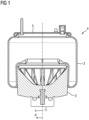
- Fig.1 shows the sectional view of an air spring system 4 with a rolling bellows air spring and a rolling piston 2 according to the invention in a side view.
- the rolling piston 2 is connected in an airtight manner to a bellows 3 of the air spring in the area of the flange and frame.
- the air spring bellows 3 rolls on the outer circumference of the rolling piston 2, forming a rolling fold.
- the rolling piston 2 is designed to be rotationally symmetrical to a longitudinal axis X in the radial direction R.
- the rolling piston 2 has a support surface 11.
- the Support surface 11 is in contact with a component connected to the rolling piston 2.
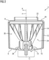
- Fig. 2 shows an exemplary design of a rolling piston 2 according to the invention in a sectional side view.
- the rolling piston 2 is designed in two parts and has as a first part a pot-shaped piston lower part 6, which comprises a piston bottom 10 and a rotationally symmetrical piston wall 12.
- the second part is formed by a piston upper part 8.
- Stiffening elements 14 are arranged between the piston bottom 10 and the piston wall 12 in the radial direction R rotationally symmetrical to the longitudinal axis X running normal to the piston bottom 10.
- the piston upper part 8 has a flange 20 and a frame 22 which protrudes axially from the flange 20 by a predetermined amount. Flange 20 and frame 22 serve to fix the bellows 3 to the rolling piston 2.
- the rib-like stiffening elements 14 have a first side surface 24 and a second side surface 26.
- a transverse stiffening element 28 is arranged between the piston crown 10 and the first side surface 24 of a first stiffening element 14 and the piston crown 10 and the second side surface 26 of a second stiffening element 14 adjacent to the first stiffening element 14.
- Each of the stiffening elements 14 is in contact with a transverse stiffening element 28.
- a transverse stiffening element 28 is arranged in every second gap formed between two stiffening elements 14.
- the transverse stiffening element 28 supports the stiffening elements 14 adjacent to one another.
- the stresses of the rib-like stiffening elements 14 are introduced into the piston crown 10 over a large area by the transverse stiffening element 28, or vice versa, thereby avoiding local stress peaks.
- the piston crown 10 When force is introduced into the piston crown 10 via the contact surface 11, the piston crown 10 may be elastically deformed in the longitudinal direction X due to high local mechanical stresses in the area of the contact surface 11. Shear stresses may occur in the piston crown 10 due to local elastic deformation.
- the piston crown 10 has a rotationally symmetrical bead 13.
- the rotationally symmetrical bead 13 allows the previously described shear stresses can be converted into compressive stresses in a particularly advantageous manner.
- the compressive stresses follow the contour of the piston head 10, whereby an optimal stress profile and a uniform stress distribution can be achieved within the piston head 10.
- the bead 13 of the piston head 10 forms a wave-shaped profile of the piston head 10 when viewed in the cross section of the rolling piston 2.
- the bead 13 can be seen from the outside as a concave contour formed by a radius and curved inwards.
- Fig.3 shows the sectional view of the Fig. 2 in an enlarged view from a perspective from below.
- the Fig.3 an enlarged view of the transverse stiffening element 28, the bead 13 and a transition element 15.
- the transition element 15 shown connects the piston crown 10 to the first side surface 24 of the rib-like stiffening element 14.
- Not shown in the sectional view is the connection of the transition element 15 to the second side surface 26 of the rib-like stiffening element 14.
- the transition element 15 is designed as a convex contour in a transition region between the piston crown 10 and the side surfaces 24, 26.
- the transition element 15 connects the transverse stiffening element 28 to the side surfaces 24, 26 of the rib-like stiffening element 14. Through the transition element 15, the mechanical stresses from the piston crown 10 and the transverse stiffening element 28 can be evenly conducted into the rib-like stiffening element 14, or vice versa.
- Fig.4 shows a rolling piston according to the invention in plan view. Reference is made to the description of the previous figures. In particular, the Fig.4 the arrangement and the course of the transition element 15 between the left and right side surfaces 24, 26 of the rib-like stiffening elements 14, the piston crown 10 and the transverse stiffening elements 28.
Landscapes
- Engineering & Computer Science (AREA)
- Mechanical Engineering (AREA)
- General Engineering & Computer Science (AREA)
- Fluid-Damping Devices (AREA)
Claims (13)
- Piston dérouleur (2) d'un système de suspension pneumatique (4),
comprenantune partie inférieure de piston en forme de pot (6),la partie inférieure de piston (6) présentant un fond de piston (10) avec une surface d'appui (11) et une paroi de piston (12) à symétrie de révolution,une partie supérieure de piston (8) reliée de manière étanche à l'air à la partie inférieure de piston (6) et se raccordant à la paroi de piston (12), réalisée sous forme de couvercle,plusieurs éléments de renforcement (14) en forme de nervure étant agencés entre le fond de piston (10) et la paroi de piston (12) dans la direction radiale (R) avec une symétrie de révolution, notamment en forme de rayons par rapport à un axe longitudinal (X) s'étendant normalement au fond de piston (10),les éléments de renforcement en forme de nervure (14) présentant une première surface latérale (24) et une deuxième surface latérale (26),la partie supérieure du piston (8) présentant une bride (20) et une jupe (22),la jupe (22) faisant saillie axialement hors de la bride (20) d'une mesure prédéterminée dans la direction opposée au fond de piston (10),caractérisé en ce quele fond de piston (10) présente une moulure périphérique (13) qui est agencée à symétrie de révolution dans la direction radiale (R) et qui présente un rayon prédéterminé. - Piston dérouleur (2) selon la revendication 1,
caractérisé en ce que
la moulure (13) délimite la surface d'appui (11) dans la direction radiale (R). - Piston dérouleur (2) selon l'une quelconque des revendications précédentes,
caractérisé en ce que
un élément de transition (15) relie le fond de piston (10) à la première surface latérale (24) et à la deuxième surface latérale (26) des éléments de renforcement en forme de nervure (14). - Piston dérouleur (2) selon l'une quelconque des revendications précédentes,
caractérisé en ce que
les éléments de renforcement en forme de nervure (14) sont reliés chacun au fond de piston (10) par au moins un élément de renforcement transversal (28). - Piston dérouleur (2) selon la revendication 4,
caractérisé en ce quel'au moins un élément de renforcement transversal (28) est relié à la première surface latérale (24) d'un premier élément de renforcement (14), au fond de piston (10) et à la deuxième surface latérale (26) d'un deuxième élément de renforcement (14),le deuxième élément de renforcement (14) étant agencé de manière voisine du premier élément de renforcement (14) dans la direction périphérique. - Piston dérouleur (2) selon l'une quelconque des revendications précédentes,
caractérisé en ce que
le piston de déroulement (2) est réalisé en matière plastique. - Piston dérouleur (2) selon l'une quelconque des revendications précédentes,
caractérisé en ce que
la liaison étanche à l'air entre la partie inférieure de piston (6) et la partie supérieure de piston (8) est réalisée sous forme de liaison soudée. - Piston dérouleur (2) selon l'une quelconque des revendications précédentes,
caractérisé en ce que
la liaison étanche à l'air entre la partie inférieure de piston (6) et la partie supérieure de piston (8) est réalisée sous forme de liaison par vis. - Piston dérouleur (2) selon l'une quelconque des revendications précédentes,
caractérisé en ce que
la liaison étanche à l'air entre la partie inférieure de piston (6) et la partie supérieure de piston (8) est réalisée sous forme de liaison adhésive. - Piston dérouleur (2) selon l'une quelconque des revendications précédentes,
caractérisé en ce que
le fond de piston (10) présente au moins un élément de liaison pour le raccordement du piston de roulement (2) à un châssis ou à une carrosserie. - Piston dérouleur (2) selon la revendication 10,
caractérisé en ce que
l'élément de liaison est réalisé sous la forme d'une douille filetée métallique injectée dans le matériau plastique ou sous la forme d'un boulon fileté métallique injecté. - Système de suspension pneumatique (4) avec un piston dérouleur (2) selon l'une quelconque des revendications précédentes.
- Véhicule automobile, notamment camion avec un système de suspension pneumatique (4) selon la revendication 12.
Applications Claiming Priority (1)
| Application Number | Priority Date | Filing Date | Title |
|---|---|---|---|
| DE102021212667.7A DE102021212667A1 (de) | 2021-11-10 | 2021-11-10 | Abrollkolben |
Publications (2)
| Publication Number | Publication Date |
|---|---|
| EP4180246A1 EP4180246A1 (fr) | 2023-05-17 |
| EP4180246B1 true EP4180246B1 (fr) | 2024-08-21 |
Family
ID=83996502
Family Applications (1)
| Application Number | Title | Priority Date | Filing Date |
|---|---|---|---|
| EP22203465.4A Active EP4180246B1 (fr) | 2021-11-10 | 2022-10-25 | Piston dérouleur |
Country Status (2)
| Country | Link |
|---|---|
| EP (1) | EP4180246B1 (fr) |
| DE (1) | DE102021212667A1 (fr) |
Family Cites Families (6)
| Publication number | Priority date | Publication date | Assignee | Title |
|---|---|---|---|---|
| JP2007321936A (ja) * | 2006-06-05 | 2007-12-13 | Fukoku Co Ltd | 空気ばね |
| DE102007035640A1 (de) * | 2007-07-27 | 2009-01-29 | Lkh-Kunststoffwerk Gmbh & Co. Kg | Tauchkolben |
| DE102011050103A1 (de) * | 2011-05-04 | 2012-11-08 | Contitech Luftfedersysteme Gmbh | Abrollkolben für einen Luftfederrollbalg |
| DE102011051237A1 (de) * | 2011-06-21 | 2012-12-27 | Contitech Luftfedersysteme Gmbh | Abrollkolben für einen Luftfederrollbalg |
| US9212717B2 (en) * | 2011-06-30 | 2015-12-15 | Firestone Industrial Products Company LLC | Gas spring end member as well as gas spring assembly including same |
| DE102017222128A1 (de) | 2017-12-07 | 2019-06-13 | Contitech Luftfedersysteme Gmbh | Luftfeder |
-
2021
- 2021-11-10 DE DE102021212667.7A patent/DE102021212667A1/de active Pending
-
2022
- 2022-10-25 EP EP22203465.4A patent/EP4180246B1/fr active Active
Also Published As
| Publication number | Publication date |
|---|---|
| EP4180246A1 (fr) | 2023-05-17 |
| DE102021212667A1 (de) | 2023-05-11 |
Similar Documents
| Publication | Publication Date | Title |
|---|---|---|
| EP2049815B1 (fr) | Ressort à air pour vehicules | |
| EP2605923B1 (fr) | Jambe de force a ressort pneumatique avec le montage souple du piston | |
| EP1144210A2 (fr) | Systeme d'amortisseur pneumatique | |
| DE102005059117B4 (de) | Aktuator für ein aktives Fahrwerk eines Kraftfahrzeugs | |
| EP0446476B1 (fr) | Piston de déroulage pour le soufflet roulant d'un ressort pneumatique à soufflet roulant | |
| DE102009036360B4 (de) | Federbeinlager zum Anschließen an einen Federbeinschaft | |
| DE112013003450B4 (de) | Endelemente für Eisenbahnfederbaugruppen und Aufhängungssysteme damit | |
| EP1831581B1 (fr) | Unite ressort et amortisseur pneumatique de guidage de roue | |
| EP4180246B1 (fr) | Piston dérouleur | |
| EP0391075A2 (fr) | Ressort pneumatique à soufflet roulant | |
| DE102021109912A1 (de) | Halbstarrachse für ein Fahrzeug | |
| DE102016212551A1 (de) | Achsanordnung für ein Kraftfahrzeug | |
| DE102019006515A1 (de) | Pneumatischer Federdämpfer | |
| DE102009003476A1 (de) | Torsionslager für Luftfeder | |
| DE102007052038A1 (de) | Hydraulischer Stabilisator, insbesondere für Fahrwerke und Fahrerhausauflagerungen | |
| DE4233106B4 (de) | Anordnung eines Blattfederstützlagers zwischen einer Radachse und einer Blattfeder in einer Radaufhängung für Fahrzeuge | |
| EP1479543B1 (fr) | Unité à ressort pneumatique et amortisseur | |
| DE102015211180A1 (de) | Radaufhängung für ein Kraftfahrzeug | |
| DE102009044031B4 (de) | Federelement für ein Fahrwerk | |
| EP2402180B1 (fr) | Axe de véhicule à suspension pneumatique | |
| DE20022663U1 (de) | Luftfederanordnung | |
| DE19833537A1 (de) | Fahrwerkslager | |
| EP3885604A1 (fr) | Piston dérouleur à ressort pneumatique | |
| DE102017221433B4 (de) | Radaufhängung | |
| DE102005059113A1 (de) | Aktuator für ein aktives Fahrwerk eines Kraftfahrzeugs |
Legal Events
| Date | Code | Title | Description |
|---|---|---|---|
| PUAI | Public reference made under article 153(3) epc to a published international application that has entered the european phase |
Free format text: ORIGINAL CODE: 0009012 |
|
| STAA | Information on the status of an ep patent application or granted ep patent |
Free format text: STATUS: THE APPLICATION HAS BEEN PUBLISHED |
|
| AK | Designated contracting states |
Kind code of ref document: A1 Designated state(s): AL AT BE BG CH CY CZ DE DK EE ES FI FR GB GR HR HU IE IS IT LI LT LU LV MC ME MK MT NL NO PL PT RO RS SE SI SK SM TR |
|
| STAA | Information on the status of an ep patent application or granted ep patent |
Free format text: STATUS: REQUEST FOR EXAMINATION WAS MADE |
|
| 17P | Request for examination filed |
Effective date: 20231117 |
|
| RBV | Designated contracting states (corrected) |
Designated state(s): AL AT BE BG CH CY CZ DE DK EE ES FI FR GB GR HR HU IE IS IT LI LT LU LV MC ME MK MT NL NO PL PT RO RS SE SI SK SM TR |
|
| RIC1 | Information provided on ipc code assigned before grant |
Ipc: F16F 9/54 20060101ALI20240205BHEP Ipc: F16F 9/05 20060101ALI20240205BHEP Ipc: B60G 11/28 20060101ALI20240205BHEP Ipc: B60G 11/27 20060101AFI20240205BHEP |
|
| GRAP | Despatch of communication of intention to grant a patent |
Free format text: ORIGINAL CODE: EPIDOSNIGR1 |
|
| STAA | Information on the status of an ep patent application or granted ep patent |
Free format text: STATUS: GRANT OF PATENT IS INTENDED |
|
| INTG | Intention to grant announced |
Effective date: 20240318 |
|
| RAP1 | Party data changed (applicant data changed or rights of an application transferred) |
Owner name: CONTITECH DEUTSCHLAND GMBH |
|
| GRAS | Grant fee paid |
Free format text: ORIGINAL CODE: EPIDOSNIGR3 |
|
| GRAA | (expected) grant |
Free format text: ORIGINAL CODE: 0009210 |
|
| STAA | Information on the status of an ep patent application or granted ep patent |
Free format text: STATUS: THE PATENT HAS BEEN GRANTED |
|
| P01 | Opt-out of the competence of the unified patent court (upc) registered |
Free format text: CASE NUMBER: APP_40526/2024 Effective date: 20240709 |
|
| AK | Designated contracting states |
Kind code of ref document: B1 Designated state(s): AL AT BE BG CH CY CZ DE DK EE ES FI FR GB GR HR HU IE IS IT LI LT LU LV MC ME MK MT NL NO PL PT RO RS SE SI SK SM TR |
|
| REG | Reference to a national code |
Ref country code: GB Ref legal event code: FG4D Free format text: NOT ENGLISH |
|
| REG | Reference to a national code |
Ref country code: CH Ref legal event code: EP |
|
| REG | Reference to a national code |
Ref country code: IE Ref legal event code: FG4D Free format text: LANGUAGE OF EP DOCUMENT: GERMAN |
|
| REG | Reference to a national code |
Ref country code: DE Ref legal event code: R096 Ref document number: 502022001503 Country of ref document: DE |
|
| REG | Reference to a national code |
Ref country code: LT Ref legal event code: MG9D |
|
| REG | Reference to a national code |
Ref country code: NL Ref legal event code: MP Effective date: 20240821 |
|
| PG25 | Lapsed in a contracting state [announced via postgrant information from national office to epo] |
Ref country code: NO Free format text: LAPSE BECAUSE OF FAILURE TO SUBMIT A TRANSLATION OF THE DESCRIPTION OR TO PAY THE FEE WITHIN THE PRESCRIBED TIME-LIMIT Effective date: 20241121 |
|
| PG25 | Lapsed in a contracting state [announced via postgrant information from national office to epo] |
Ref country code: NL Free format text: LAPSE BECAUSE OF FAILURE TO SUBMIT A TRANSLATION OF THE DESCRIPTION OR TO PAY THE FEE WITHIN THE PRESCRIBED TIME-LIMIT Effective date: 20240821 Ref country code: PL Free format text: LAPSE BECAUSE OF FAILURE TO SUBMIT A TRANSLATION OF THE DESCRIPTION OR TO PAY THE FEE WITHIN THE PRESCRIBED TIME-LIMIT Effective date: 20240821 Ref country code: FI Free format text: LAPSE BECAUSE OF FAILURE TO SUBMIT A TRANSLATION OF THE DESCRIPTION OR TO PAY THE FEE WITHIN THE PRESCRIBED TIME-LIMIT Effective date: 20240821 Ref country code: GR Free format text: LAPSE BECAUSE OF FAILURE TO SUBMIT A TRANSLATION OF THE DESCRIPTION OR TO PAY THE FEE WITHIN THE PRESCRIBED TIME-LIMIT Effective date: 20241122 Ref country code: PT Free format text: LAPSE BECAUSE OF FAILURE TO SUBMIT A TRANSLATION OF THE DESCRIPTION OR TO PAY THE FEE WITHIN THE PRESCRIBED TIME-LIMIT Effective date: 20241223 |
|
| PG25 | Lapsed in a contracting state [announced via postgrant information from national office to epo] |
Ref country code: BG Free format text: LAPSE BECAUSE OF FAILURE TO SUBMIT A TRANSLATION OF THE DESCRIPTION OR TO PAY THE FEE WITHIN THE PRESCRIBED TIME-LIMIT Effective date: 20240821 |
|
| PG25 | Lapsed in a contracting state [announced via postgrant information from national office to epo] |
Ref country code: LV Free format text: LAPSE BECAUSE OF FAILURE TO SUBMIT A TRANSLATION OF THE DESCRIPTION OR TO PAY THE FEE WITHIN THE PRESCRIBED TIME-LIMIT Effective date: 20240821 |
|
| PG25 | Lapsed in a contracting state [announced via postgrant information from national office to epo] |
Ref country code: IS Free format text: LAPSE BECAUSE OF FAILURE TO SUBMIT A TRANSLATION OF THE DESCRIPTION OR TO PAY THE FEE WITHIN THE PRESCRIBED TIME-LIMIT Effective date: 20241221 |
|
| PG25 | Lapsed in a contracting state [announced via postgrant information from national office to epo] |
Ref country code: HR Free format text: LAPSE BECAUSE OF FAILURE TO SUBMIT A TRANSLATION OF THE DESCRIPTION OR TO PAY THE FEE WITHIN THE PRESCRIBED TIME-LIMIT Effective date: 20240821 |
|
| PG25 | Lapsed in a contracting state [announced via postgrant information from national office to epo] |
Ref country code: RS Free format text: LAPSE BECAUSE OF FAILURE TO SUBMIT A TRANSLATION OF THE DESCRIPTION OR TO PAY THE FEE WITHIN THE PRESCRIBED TIME-LIMIT Effective date: 20241121 Ref country code: ES Free format text: LAPSE BECAUSE OF FAILURE TO SUBMIT A TRANSLATION OF THE DESCRIPTION OR TO PAY THE FEE WITHIN THE PRESCRIBED TIME-LIMIT Effective date: 20240821 |
|
| PG25 | Lapsed in a contracting state [announced via postgrant information from national office to epo] |
Ref country code: RS Free format text: LAPSE BECAUSE OF FAILURE TO SUBMIT A TRANSLATION OF THE DESCRIPTION OR TO PAY THE FEE WITHIN THE PRESCRIBED TIME-LIMIT Effective date: 20241121 Ref country code: PT Free format text: LAPSE BECAUSE OF FAILURE TO SUBMIT A TRANSLATION OF THE DESCRIPTION OR TO PAY THE FEE WITHIN THE PRESCRIBED TIME-LIMIT Effective date: 20241223 Ref country code: PL Free format text: LAPSE BECAUSE OF FAILURE TO SUBMIT A TRANSLATION OF THE DESCRIPTION OR TO PAY THE FEE WITHIN THE PRESCRIBED TIME-LIMIT Effective date: 20240821 Ref country code: NO Free format text: LAPSE BECAUSE OF FAILURE TO SUBMIT A TRANSLATION OF THE DESCRIPTION OR TO PAY THE FEE WITHIN THE PRESCRIBED TIME-LIMIT Effective date: 20241121 Ref country code: NL Free format text: LAPSE BECAUSE OF FAILURE TO SUBMIT A TRANSLATION OF THE DESCRIPTION OR TO PAY THE FEE WITHIN THE PRESCRIBED TIME-LIMIT Effective date: 20240821 Ref country code: LV Free format text: LAPSE BECAUSE OF FAILURE TO SUBMIT A TRANSLATION OF THE DESCRIPTION OR TO PAY THE FEE WITHIN THE PRESCRIBED TIME-LIMIT Effective date: 20240821 Ref country code: IS Free format text: LAPSE BECAUSE OF FAILURE TO SUBMIT A TRANSLATION OF THE DESCRIPTION OR TO PAY THE FEE WITHIN THE PRESCRIBED TIME-LIMIT Effective date: 20241221 Ref country code: HR Free format text: LAPSE BECAUSE OF FAILURE TO SUBMIT A TRANSLATION OF THE DESCRIPTION OR TO PAY THE FEE WITHIN THE PRESCRIBED TIME-LIMIT Effective date: 20240821 Ref country code: GR Free format text: LAPSE BECAUSE OF FAILURE TO SUBMIT A TRANSLATION OF THE DESCRIPTION OR TO PAY THE FEE WITHIN THE PRESCRIBED TIME-LIMIT Effective date: 20241122 Ref country code: FI Free format text: LAPSE BECAUSE OF FAILURE TO SUBMIT A TRANSLATION OF THE DESCRIPTION OR TO PAY THE FEE WITHIN THE PRESCRIBED TIME-LIMIT Effective date: 20240821 Ref country code: ES Free format text: LAPSE BECAUSE OF FAILURE TO SUBMIT A TRANSLATION OF THE DESCRIPTION OR TO PAY THE FEE WITHIN THE PRESCRIBED TIME-LIMIT Effective date: 20240821 Ref country code: BG Free format text: LAPSE BECAUSE OF FAILURE TO SUBMIT A TRANSLATION OF THE DESCRIPTION OR TO PAY THE FEE WITHIN THE PRESCRIBED TIME-LIMIT Effective date: 20240821 |
|
| PG25 | Lapsed in a contracting state [announced via postgrant information from national office to epo] |
Ref country code: DK Free format text: LAPSE BECAUSE OF FAILURE TO SUBMIT A TRANSLATION OF THE DESCRIPTION OR TO PAY THE FEE WITHIN THE PRESCRIBED TIME-LIMIT Effective date: 20240821 Ref country code: RO Free format text: LAPSE BECAUSE OF FAILURE TO SUBMIT A TRANSLATION OF THE DESCRIPTION OR TO PAY THE FEE WITHIN THE PRESCRIBED TIME-LIMIT Effective date: 20240821 Ref country code: SM Free format text: LAPSE BECAUSE OF FAILURE TO SUBMIT A TRANSLATION OF THE DESCRIPTION OR TO PAY THE FEE WITHIN THE PRESCRIBED TIME-LIMIT Effective date: 20240821 |
|
| PG25 | Lapsed in a contracting state [announced via postgrant information from national office to epo] |
Ref country code: EE Free format text: LAPSE BECAUSE OF FAILURE TO SUBMIT A TRANSLATION OF THE DESCRIPTION OR TO PAY THE FEE WITHIN THE PRESCRIBED TIME-LIMIT Effective date: 20240821 |
|
| PG25 | Lapsed in a contracting state [announced via postgrant information from national office to epo] |
Ref country code: CZ Free format text: LAPSE BECAUSE OF FAILURE TO SUBMIT A TRANSLATION OF THE DESCRIPTION OR TO PAY THE FEE WITHIN THE PRESCRIBED TIME-LIMIT Effective date: 20240821 |
|
| PG25 | Lapsed in a contracting state [announced via postgrant information from national office to epo] |
Ref country code: IT Free format text: LAPSE BECAUSE OF FAILURE TO SUBMIT A TRANSLATION OF THE DESCRIPTION OR TO PAY THE FEE WITHIN THE PRESCRIBED TIME-LIMIT Effective date: 20240821 Ref country code: SK Free format text: LAPSE BECAUSE OF FAILURE TO SUBMIT A TRANSLATION OF THE DESCRIPTION OR TO PAY THE FEE WITHIN THE PRESCRIBED TIME-LIMIT Effective date: 20240821 |
|
| REG | Reference to a national code |
Ref country code: DE Ref legal event code: R097 Ref document number: 502022001503 Country of ref document: DE |
|
| PLBE | No opposition filed within time limit |
Free format text: ORIGINAL CODE: 0009261 |
|
| STAA | Information on the status of an ep patent application or granted ep patent |
Free format text: STATUS: NO OPPOSITION FILED WITHIN TIME LIMIT |
|
| PG25 | Lapsed in a contracting state [announced via postgrant information from national office to epo] |
Ref country code: MC Free format text: LAPSE BECAUSE OF FAILURE TO SUBMIT A TRANSLATION OF THE DESCRIPTION OR TO PAY THE FEE WITHIN THE PRESCRIBED TIME-LIMIT Effective date: 20240821 |
|
| PG25 | Lapsed in a contracting state [announced via postgrant information from national office to epo] |
Ref country code: LU Free format text: LAPSE BECAUSE OF NON-PAYMENT OF DUE FEES Effective date: 20241025 Ref country code: BE Free format text: LAPSE BECAUSE OF NON-PAYMENT OF DUE FEES Effective date: 20241031 |
|
| 26N | No opposition filed |
Effective date: 20250522 |
|
| REG | Reference to a national code |
Ref country code: BE Ref legal event code: MM Effective date: 20241031 |
|
| PG25 | Lapsed in a contracting state [announced via postgrant information from national office to epo] |
Ref country code: SE Free format text: LAPSE BECAUSE OF FAILURE TO SUBMIT A TRANSLATION OF THE DESCRIPTION OR TO PAY THE FEE WITHIN THE PRESCRIBED TIME-LIMIT Effective date: 20240821 |
|
| PG25 | Lapsed in a contracting state [announced via postgrant information from national office to epo] |
Ref country code: IE Free format text: LAPSE BECAUSE OF NON-PAYMENT OF DUE FEES Effective date: 20241025 |
|
| PGFP | Annual fee paid to national office [announced via postgrant information from national office to epo] |
Ref country code: DE Payment date: 20251031 Year of fee payment: 4 |
|
| PGFP | Annual fee paid to national office [announced via postgrant information from national office to epo] |
Ref country code: AT Payment date: 20260113 Year of fee payment: 4 |
|
| PGFP | Annual fee paid to national office [announced via postgrant information from national office to epo] |
Ref country code: FR Payment date: 20251030 Year of fee payment: 4 |
|
| PGFP | Annual fee paid to national office [announced via postgrant information from national office to epo] |
Ref country code: TR Payment date: 20251020 Year of fee payment: 4 |
|
| PG25 | Lapsed in a contracting state [announced via postgrant information from national office to epo] |
Ref country code: CY Free format text: LAPSE BECAUSE OF FAILURE TO SUBMIT A TRANSLATION OF THE DESCRIPTION OR TO PAY THE FEE WITHIN THE PRESCRIBED TIME-LIMIT; INVALID AB INITIO Effective date: 20221025 |
|
| PG25 | Lapsed in a contracting state [announced via postgrant information from national office to epo] |
Ref country code: HU Free format text: LAPSE BECAUSE OF FAILURE TO SUBMIT A TRANSLATION OF THE DESCRIPTION OR TO PAY THE FEE WITHIN THE PRESCRIBED TIME-LIMIT; INVALID AB INITIO Effective date: 20221025 |