EP4180331A1 - Système de sauvetage pour un aéronef - Google Patents
Système de sauvetage pour un aéronef Download PDFInfo
- Publication number
- EP4180331A1 EP4180331A1 EP22206922.1A EP22206922A EP4180331A1 EP 4180331 A1 EP4180331 A1 EP 4180331A1 EP 22206922 A EP22206922 A EP 22206922A EP 4180331 A1 EP4180331 A1 EP 4180331A1
- Authority
- EP
- European Patent Office
- Prior art keywords
- diameter
- main
- reefing
- container
- parachute
- Prior art date
- Legal status (The legal status is an assumption and is not a legal conclusion. Google has not performed a legal analysis and makes no representation as to the accuracy of the status listed.)
- Granted
Links
Images


Classifications
-
- B—PERFORMING OPERATIONS; TRANSPORTING
- B64—AIRCRAFT; AVIATION; COSMONAUTICS
- B64D—EQUIPMENT FOR FITTING IN OR TO AIRCRAFT; FLIGHT SUITS; PARACHUTES; ARRANGEMENT OR MOUNTING OF POWER PLANTS OR PROPULSION TRANSMISSIONS IN AIRCRAFT
- B64D17/00—Parachutes
- B64D17/80—Parachutes in association with aircraft, e.g. for braking thereof
-
- B—PERFORMING OPERATIONS; TRANSPORTING
- B64—AIRCRAFT; AVIATION; COSMONAUTICS
- B64C—AEROPLANES; HELICOPTERS
- B64C27/00—Rotorcraft; Rotors peculiar thereto
- B64C27/006—Safety devices
-
- B—PERFORMING OPERATIONS; TRANSPORTING
- B64—AIRCRAFT; AVIATION; COSMONAUTICS
- B64D—EQUIPMENT FOR FITTING IN OR TO AIRCRAFT; FLIGHT SUITS; PARACHUTES; ARRANGEMENT OR MOUNTING OF POWER PLANTS OR PROPULSION TRANSMISSIONS IN AIRCRAFT
- B64D17/00—Parachutes
- B64D17/40—Packs
-
- B—PERFORMING OPERATIONS; TRANSPORTING
- B64—AIRCRAFT; AVIATION; COSMONAUTICS
- B64D—EQUIPMENT FOR FITTING IN OR TO AIRCRAFT; FLIGHT SUITS; PARACHUTES; ARRANGEMENT OR MOUNTING OF POWER PLANTS OR PROPULSION TRANSMISSIONS IN AIRCRAFT
- B64D25/00—Emergency apparatus or devices, not otherwise provided for
- B64D25/08—Ejecting or escaping means
- B64D25/12—Ejectable capsules
-
- B—PERFORMING OPERATIONS; TRANSPORTING
- B64—AIRCRAFT; AVIATION; COSMONAUTICS
- B64U—UNMANNED AERIAL VEHICLES [UAV]; EQUIPMENT THEREFOR
- B64U10/00—Type of UAV
- B64U10/10—Rotorcrafts
-
- B—PERFORMING OPERATIONS; TRANSPORTING
- B64—AIRCRAFT; AVIATION; COSMONAUTICS
- B64U—UNMANNED AERIAL VEHICLES [UAV]; EQUIPMENT THEREFOR
- B64U10/00—Type of UAV
- B64U10/10—Rotorcrafts
- B64U10/17—Helicopters
-
- B—PERFORMING OPERATIONS; TRANSPORTING
- B64—AIRCRAFT; AVIATION; COSMONAUTICS
- B64U—UNMANNED AERIAL VEHICLES [UAV]; EQUIPMENT THEREFOR
- B64U30/00—Means for producing lift; Empennages; Arrangements thereof
- B64U30/20—Rotors; Rotor supports
-
- B—PERFORMING OPERATIONS; TRANSPORTING
- B64—AIRCRAFT; AVIATION; COSMONAUTICS
- B64U—UNMANNED AERIAL VEHICLES [UAV]; EQUIPMENT THEREFOR
- B64U70/00—Launching, take-off or landing arrangements
- B64U70/80—Vertical take-off or landing, e.g. using rockets
- B64U70/83—Vertical take-off or landing, e.g. using rockets using parachutes, balloons or the like
Definitions
- Aircraft can in particular be unmanned aircraft or drones. Special requirements arise when the drone is an aircraft in the rotorcraft category.
- rescue systems for rotorcraft particular care must be taken to avoid the parachute and/or its lines coming into contact with a rotor or other moving components of the rotorcraft during or after deployment of the parachute in an emergency situation in such a way that the rescue system is damaged and/or its overall function is negatively affected.
- a rescue parachute is pushed off the rotorcraft with as much force as possible by means of a pyrotechnic propellant.
- the present invention is based on the object of providing a rescue system which protects an aircraft from an uncontrolled crash and at the same time ensures reliable deployment of the rescue system without being damaged by the aircraft.
- a further object consists in providing a rescue system which is designed in such a way that the flight characteristics of the aircraft are impaired as little as possible when such a rescue system is retrofitted.
- the rescue system according to the invention for an aircraft that is a rotorcraft comprises a main parachute with a main line and a plurality of main parachute lines, the main line connecting the main parachute to the aircraft on which the rescue system is installed.
- the system further includes an outer container having a first diameter disposed on an exterior of the aircraft longitudinally along a tail boom of the rotorcraft, and an inner container disposed within the outer container and adapted to house the main chute.
- the inner container preferably has a reefing area with a second diameter, with the second diameter of the reefing area being reefed to a diameter which is smaller than the first diameter of the outer container when the Main chute located within the inner container, a release line securing the loops in the grommets thereby maintaining reefing of the inner container and a line section, the line section being located at a first end of the reef section and being suitable for the plurality of take up main parachute lines.
- a compression area is provided which has a diameter, the third diameter being smaller than the second diameter and essentially corresponding to the reefed diameter of the reefing area.
- the compression area can preferably be arranged at a second end of the reefing area.
- the rescue system can have a device for attaching an auxiliary chute, in which case the compression area can preferably be arranged between the device for attaching the auxiliary chute and the reefing area.
- the outer container can have a tubular structure and the inner container can have a tubular structure, so that a secure arrangement of the inner container in the outer container can be ensured.
- Such an arrangement of the inner container in the outer container, as described above, also has the advantage that the inner hose can be reliably transported out of the outer container and opened without damaging the rescue parachute when it is deployed or opened by parts of the aircraft to risk.
- the rescue system has an auxiliary chute which is connected to the inner container by means of the device for attaching the auxiliary chute and can thus ensure rapid deployment of the rescue chute.
- the main line can be connected to the release line in such a way that the release line is only pulled out of the pairs of loops and eyelets when the inner container has been pulled completely out of the outer container by the auxiliary chute.
- This way of deploying the rescue parachute is advantageous in that the parachute is reefed and can therefore be easily pulled out of the outer container until the inner container is completely clear of the outer container and away from the aircraft before the rescue parachute is deployed.
- the auxiliary chute of the rescue system can also advantageously be deployed purely mechanically, ie without the use of pyrotechnics. Purely mechanical reject mechanisms are based, for example, on spring force or compressed air.
- Rescue systems that use a propellant, such as rocket propulsion, to ensure that the rescue parachute goes far enough is removed from the aircraft before it is deployed have the disadvantage that damage to the reserve parachute by the aircraft is avoided, but this is accompanied by the risk of damage to the reserve parachute by the propellant charge itself.
- the rescue system according to the invention can have an emergency detection module.
- an emergency detection module enables precise monitoring of the aircraft's avionics, as well as a critical analysis of the flight data determined, making it possible to create various emergency scenarios in order to minimize the risk of the rescue system being deployed incorrectly.
- the line section of the inner container may have a plurality of pockets suitable for receiving the main parachute lines.
- Such an arrangement allows the main parachute lines to be safely stowed away, which in turn ensures reliable opening of the rescue parachute.
- the outer container can have a protective cap which, when an emergency is detected, is blown off the outer container purely mechanically by the emergency detection module, for example by means of a spring mechanism.
- the protective cap can be designed in such a way that it is destroyed or bursts by the pressure of the auxiliary chute when the auxiliary chute is deployed.
- Such protective caps are typically made of rupture foil.
- the main line can be connected to a rotor axis of the rotorcraft by means of a connection system, so that in an unfolded state of the main chute, the main line of the main chute is rotatably attached substantially in the vicinity of the center of gravity of the rotorcraft, creating a horizontal Position of the rotorcraft in the deployed condition of the rescue parachute can be achieved, thereby reducing the risk of damage to the rotor or other parts of the rotorcraft.
- Another aspect of the present invention relates to a case for holding a parachute, the case being tubular and comprising three areas in the following sequence: a compression area designed to hold a first part of the parachute, a reefing area with a plurality of loops -eyelet pairs designed to receive a second part of the parachute, the loop-eyelet pairs being arranged in pairs along the reefing area on the outside of the container in such a way that a loop can be fixed to a respective eyelet and a diameter of the Container in the reefing area is reduced by reefing, and a line area which is designed to accommodate a plurality of lines of the parachute, wherein a release line for fixing the plurality of loops to the respective eyelets can be used in such a way that removing the release line fixes the Loop-eyelet pairs loosen and the diameter of the container in the reefing area is increased by unloading.
- the container can be designed in such a way that the reefing area has a first diameter, with the plurality of loop-eyelet pairs being used to reef the first diameter of the reefing area essentially to a diameter that is smaller than the first diameter when the Parachute is located within the container, whereby storage of the parachute can be achieved in such a way that the tubular container has a substantially the same diameter over its entire length.
- the compression area can have a second diameter, the second diameter being smaller than the first diameter and essentially corresponding to the reefed diameter of the reefing area.
- the line portion of the case may have a plurality of pockets suitable for accommodating the majority of the lines of the parachute, whereby reliable opening of the parachute can be achieved.
- the present invention relates to a rescue system for an aircraft and to a container for holding a parachute.
- Aircraft in this context are manned or unmanned drones, for example multi-rotor or single-rotor helicopter type rotorcraft drones.
- Other aircraft for which the rescue system according to the invention is suitable are, for example, fixed-wing drones.
- Experiments with the rescue system according to the invention took place, for example, with a single-rotor helicopter drone with a maximum take-off weight of 150 kg and a top speed of 140 km/h.
- the invention is not limited to the application for this specific drone.
- the rescue system according to the invention is based on the opening of a parachute and the resulting reduction in the rate of fall of the drone after deployment of the parachute in an emergency situation. This enables the aircraft to land relatively gently after an emergency occurs.
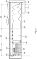
- FIG 1 shows an overview of the rescue system including an aircraft.
- the aircraft is shown as a single-rotor helicopter drone 130 with the main chute 120 and auxiliary chute 110 deployed, called the "pilot chute".
- the auxiliary screen 110 is smaller than the main screen 120.
- the main parachute 120 is connected to the aircraft via a main line 125 and several suspension lines or main parachute lines 128 .
- the auxiliary screen 110 is connected to the main screen 120 and the main screen line 125 by means of an auxiliary screen line 115 .
- the rescue system includes an elongated tubular outer container 135 which is arranged and mounted along a tail boom of the helicopter drone 130 .
- This outer container 135 includes, among other things, an inner container and the main parachute 120 in the folded state (not in 1 shown).
- the arrangement of the rescue system along the tail boom of the helicopter drone is aerodynamic and also advantageous in terms of weight distribution. This design feature of the rescue system, which makes this arrangement possible, makes the system particularly attractive for retrofitting to drones.
- the outer container 135 is closed at the stern by a protective cover 136, preventing ingress of debris and moisture during normal operation of the drone, ie not in emergency operation.
- the cover 136 can be a covering cap or also a foil, for example a bursting foil.
- the one in which in 1 arrangement shown aft portion of the tubular outer container 135 to or beyond a radius of the tail rotor.
- FIG. 2 shows a schematic structure of the rescue system and its details in the non-deployed state.
- the rescue system includes an outer container 235 with a first diameter, which is arranged on an outside of the aircraft 130 .
- This outer container 235 serves as a protective device for the other components of the rescue system described below.
- the elongated design of the outer container is advantageous and is due to aerodynamics and the weight distribution during flight operations of the aircraft 130.
- the elongated design of the outer container 235 and thus the rescue system as a whole is not unproblematic with regard to the requirement that the deployment process and the associated deployment of the main parachute 220 must take place very quickly and reliably.
- the outer container 235 is preferably made of a light and strong material such as aluminum alloy or carbon.
- the diameter of the outer container depends on the size of the parachute.
- the size of the parachute in turn, depends on the take-off weight of the drone.
- a rescue system for drones with a maximum take-off weight of 150 kg should have a diameter of between 5 and 15 cm for the outer container.
- the rescue system also includes an inner container 250 which, in a non-deployed state, is arranged in the outer container 235 and is suitable for accommodating the main parachute 120 .
- the rescue system also includes a main parachute 220 with a main line 225 and a plurality of suspension lines 228, also referred to herein as main parachute lines, the main line 225 connecting the main parachute 220 to the aircraft 130 on which the rescue system is installed.
- the main line 225 has a loop at the end installed on the aircraft, which is laid around the axis of a rotor head as a loop coupling, specifically the axis of the central rotor of the aircraft 130.
- Hanging the aircraft on the rotor head using the loop coupling principle has the advantage that the aircraft can land on the landing gear in a controlled manner, which can absorb the energy of the landing impact well.
- the rescue system can also be used without a loop coupling, in that the aircraft 130 glides to the ground suspended at the rear.
- the section of the main line 225 that is remote from the main chute 220 is routed inside the aircraft 130, as described, and placed around the rotor axis as a loop coupling.
- the rescue system is triggered, the main line 225 comes under tension and releases predetermined breaking points on the fuselage of the aircraft 130, so that the aircraft 130 is in the fully tensioned state of the main line 120, as in the left-hand part of the figure 1 shown hanging vertically below main canopy 120 when main canopy 120 is fully deployed.
- a rotatable coupling called swivel 229 is installed between main line 225 and main parachute lines 228 .
- This coupling decouples the rotation of the rotor of the aircraft 130 from the main chute 220. In other words, due to the vortex 229, rotation of the rotor does not result in rotation of the main chute lines 228 and the main chute 220.
- FIG. 2 also shows an optional opening retarder 242, a so-called slider 242, which delays deployment of the main canopy 220, particularly at high speed of the aircraft, and allows controlled deployment of the main canopy 220.
- FIG. 12 shows that the main chute lines 228 are preferably stowed in canvas pockets 230.
- FIG. This type of packing of the main parachute lines 228 enables the lines to be unfolded quickly after the rescue system has been deployed and at the same time prevents them from becoming tangled.
- the inner container 250 is described in detail below.
- the inner container 250 is a receptacle for receiving the main umbrella 220.
- the inner container 250 is preferably tubular and is open at least at one end where the main umbrella 220 is inserted into the receptacle.
- the inner container is preferably made of a lightweight, lubricious fabric such as balloon silk
- the inner container 250 is stored inside the outer container 235 in the non-deployed state.
- the inner container 250 is designed in such a way that it can very quickly and easily escape from the outer container 235 at the end of the detached cover 236 when the rescue device is deployed.
- the main parachute contained therein can also escape from the outer container 235 with the inner container 250 .
- the diameter of the inner container 250 when packed, ie with the main parachute contained therein, is smaller than the inner diameter of the outer container 235 throughout, ie over the entire length Container 235 is stored and is not brought into the outer container 235 only after deformation.
- a conventional parachute packing is, for example, parallelepipedal or similar, and differs significantly from the main parachute packing shape described herein in the form of a substantially elongate cylinder of substantially uniform but constrained diameter (see Fig 3 ).
- the inner container 250 preferably comprises three regions, which are described in detail below. These areas can overlap.
- the three areas are arranged in the following sequence in the longitudinal direction of the inner container 250: line area 203, reefing area 205, and compression area 208.
- the inner container 250 includes the line portion 203 which is adapted to receive a plurality of the main parachute lines 228 .
- the line area 203 preferably includes the line pockets 230, which are attached and sewn to the outside of the inner container 250. When the rescue system is packed, bundles of sections of the main parachute lines 228 are stowed away in these canvas bags 230 .
- the line pockets 230 are opened on at least one side to insert one or more lines.
- the line area 203 is arranged at a first end of the reefing area 205 and can optionally also overlap with the reefing area 205 .
- the inner container 250 also includes the reefing area 205 with a second diameter, with the second diameter of the reefing area being reefed by means of a plurality of loop-eyelet pairs 280 essentially to a diameter which is smaller than the inner diameter of the outer container 235, when the main parachute 220 is inside the inner container 250, with a release line 285 fixing the loops in the eyelets and thereby reefing the first container maintained.
- a release line is also referred to as a "flex pin” or splint line. It is preferably made of a flexible smooth material, such as nylon wire.”
- the plurality of loop-eyelet pairs 280 along the reefing area 205 are arranged in pairs on the outside of the inner container 250 such that a loop can be fixed to a respective eyelet and a diameter of the inner container 250 in the reefing area 205 is reduced by reefing.
- the diameter of the reefing area 205 when reefed is smaller than the first diameter of the outer container 235.
- the diameter of the reefing area 205 when unreefed is larger than the inner diameter of the outer container 235.
- the release line 285 is used to fix the plurality of loops to the respective eyelets in such a way that removing, for example pulling out, the release line 285 releases the fixation of the loop-eyelet pairs and the diameter of the inner container 250 in the reefing area 205 increases by hitting it becomes.
- the inner container 250 further includes a compression section (208, 308) having a diameter less than the diameter of the reefed section 205 when unreefed and substantially equal to the diameter of the reefed section when reefed and less than the inner diameter of the outer Containers 235.
- Compression section 208 is located at an end of reefing section 205 opposite the end at which line section 203 is located.
- the inner container further comprises a device 290 for attaching an auxiliary chute 210, wherein the compression area 208, as in 2 shown, is arranged between the device 290 for attaching the auxiliary chute 210 and the reefing area 205.
- the device 290 for attaching the pilot chute 210 preferably allows connection to a pilot chute line.
- the sub-chute 210 is preferably contained in a sub-chute container 292 when packaged.
- the auxiliary parachute container 292 can, as in 2 shown to be separate from the outer container 235.
- the cover 236 can preferably close the outer container 235 and the auxiliary parachute container 292.
- the rescue system is triggered in the following steps: (a) An emergency detection module determines, for example by evaluating current sensor data, that an emergency situation is present and the rescue system should be triggered. (b) A control signal opens the cover 236, which is mechanically separated or folded away from the outer container 235, for example.
- the pilot chute 210 is ejected using a mechanical ejection device; (d) the auxiliary screen 210 opens; (e) the pilot chute 210 pulls the inner container 250 out of the outer container 235 through the pilot chute line 215; (f) release line 285 is pulled at or shortly after inner container 250 is conveyed out of outer container 235, thus releasing the paired connections between loops and eyes 280; (g) reef area 205 widens by encounter; (h) the main chute 220 falls out of the inner container 250 by gravity or the inner container 250 is pulled off the main chute 220 through the connection to the auxiliary chute 210 by means of the device 290 for attaching the auxiliary chute 210; in other words, the extraction, from the outer container 235 and then from the inner container 235, of the main chute 220 takes place by the force of the auxiliary chute 210; (i) the main screen 220 deploys, possibly delayed due to the optional slider 242; (j) the main line 225 of the skin chute 220 pulls, stretches
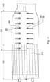
- the main line 325 connects the main chute 220 to the aircraft 130.
- the release line 385 is connected to the main line 325 at one end. By pulling on the main line 325, the release line 385 is pulled out of the loops 380, so that the loops are released from the eyelets and the reefing area 305 is hit.
- This correspondence facilitates the stripping of the inner container 350 from the main chute 220 during the deployment process 3
- the line area 303 is shown with the filled line bags seen from the outside.
- the part of the lower canopy of the main parachute that is larger in terms of material volume is typically located in the reefing area 305 .
- this part of the inner container 350 can be reduced to a value which is less than the inner diameter of the outer container 235.
- the compression area 308 the remaining parts of the folded main canopy, in particular its upper canopy, are stowed.
- the device 390 for attaching the auxiliary screen 210 is shown. This device can be, for example, an eyelet or thimble fixed in the fabric of the inner container 350 .
- FIG. 4 Figure 12 shows a detail of the inner container 250 for the main chute 220 in the packed condition, and the main line 425 of the main chute 220, the release line 485 and the eyelet and loop combination 480 in the connected condition.
- the sewn loops 481 are shown on the outside of the outer container 250, and the eyelets 482 sewn in pairs to form the loops on the outside of the outer container 250 can also be seen.
- FIG 5 Figure 12 shows the same portion of the outer container 250 as 4 , but in the open, ie not packed state.
- the diameter of the reefing area 505 in the unreefed state is significantly larger than the diameter of the compression area 508. It can also be seen that the reefing area 505 partially overlaps with the line area 503.
- the grommets 580 are secured with a fabric strap 582 sewn to the outside of the outer container 250 . Opposite is located in pairs to the eyelets, a loop 583, which is also sewn in its continuation 581 on the outside of the outer container 250.
- Figure 6A shows a detail of the eyelet 680, the sewn fabric band 682 and the corresponding loop 683 in the unreefed state of the reefing area.
- Figure 6B shows a detail of the eyelet 680, the sewn fabric tape 682 and the corresponding loop 683 in the gathered state of the reefing area. It can be seen that the loop 683 is passed through the eyelet 680 and the release line 685 is passed through the end of the loop 683 protruding beyond the passage through the eyelet 683 . The loop is thus retained on the eyelet, which maintains reefing of the inner container 250 filled with the main parachute 220 when folded. Pulling out the release line 685 releases this paired connection between the opposite eyelet and loop and leads to the escape.
- Embodiment 1 Rescue system for an aircraft 130 which is a rotorcraft, comprising: a main parachute 120 having a main line 125 and a plurality of main parachute lines 128, the main line 125 connecting the main parachute to the aircraft 130 on which the rescue system is installed; an outer container 135, 235 having a first diameter disposed on an outside of the aircraft longitudinally along a tail boom; an inner container 250 placed inside the outer container and adapted to receive the main chute 120.
- Embodiment 2 Rescue system according to embodiment 9 or 10, wherein the main line 125 is connected to a rotor axis of the rotorcraft 135 by means of a connection system, so that when the main chute 120 is in an unfolded state, the main line 125 of the main chute 120 is essentially in the vicinity of the center of gravity of the Rotorcraft 130 is rotatably mounted.
- Embodiment 3 Rescue system according to embodiment 1 or 2, wherein the inner container 250, further comprises the following: a reefing area 205, 305 with a second diameter, wherein by means of a plurality of loop-eyelet pairs 280, the second diameter of the reefing area is essentially reduced to one reefing to a diameter less than the first diameter of the outer container 135, 235 when the main chute is within the first container, with a release line 285 securing the loops in the grommets thereby maintaining reefing of the first container; a line section 303, the line section being located at a first end of the reefing section and adapted to receive the plurality of main chute lines 128; a compression section 208 having a third diameter, the third diameter being less than the second diameter and substantially equal to the reefed diameter of the reefed section, the compression section 208 being located at a second end of the reefed section 205, 305; a device 290 for attaching an auxiliary chute 110, 210, the compression area 208 being arranged
- Embodiment 4 Rescue system according to embodiment 3, wherein the rescue system has an auxiliary chute which is connected to the inner container by means of the device for attaching the auxiliary chute.
- Exemplary embodiment 5 Rescue system according to exemplary embodiment 3, wherein the main line is connected to the release line 285 in such a way that the release line is pulled out of the loop-eyelet pairs when the inner container has been pulled completely out of the outer container by the auxiliary chute.
- Exemplary embodiment 6 Rescue system according to exemplary embodiment 4 or 5, with the auxiliary chute 110 being deployed mechanically.
- Exemplary embodiment 7 Rescue system according to one of the preceding exemplary embodiments, the rescue system having an emergency detection module.
- Exemplary embodiment 8 Rescue system according to one of the exemplary embodiments 3-7, wherein the line area 203 has a plurality of pockets 570 which are suitable for receiving the main parachute lines 128.
- Exemplary embodiment 9 Rescue system according to one of the preceding exemplary embodiments, the outer container 135 having a protective cap 136 which, in the event of an emergency being detected, is blown off the outer container 135 mechanically, for example via a spring mechanism.
- Embodiment 10 Case 250 for receiving a parachute 120 the case 250 being tubular and comprising three areas in the following sequence: a compression area 208 adapted to receive a first part of the parachute; a reefing area 205 with a plurality of loop-eyelet pairs 280, which is designed to receive a second part of the parachute, the loop-eyelet pairs being arranged in pairs along the reefing area 205, 305 on the outside of the container 250 in such a way, that a loop can be fixed to a respective eyelet and a diameter of the container in the reefing area 305 is reduced by reefing; and a line section 303 adapted to receive a plurality of lines 125, 128 of the parachute 120; wherein a release line 285 for fixing the plurality of loops to the respective eyelets can be used in such a way that a Removing the release line 285 releases the fixation of the pairs of loops and eyelets and the diameter of the container in the reefing area 205 is increased by unload
- Exemplary embodiment 11 Container according to exemplary embodiment 10, wherein the reefing area has a first diameter, with the first diameter of the reefing area 205, 305 being reefed essentially to a diameter that is smaller than the first diameter by means of the plurality of loop-eyelet pairs 280, when the reserve parachute 120 is inside the container 250.
- Exemplary embodiment 12 Container according to exemplary embodiment 10 or 11, wherein the compression area 208 has a second diameter, the second diameter being smaller than the first diameter and essentially corresponding to the reefed diameter of the reefing area 205.
- Exemplary embodiment 13 Container according to any one of exemplary embodiments 10-12, wherein the line region 303 has a plurality of pockets 570 which are suitable for receiving the plurality of lines 125, 128 of the parachute 120.
Landscapes
- Engineering & Computer Science (AREA)
- Aviation & Aerospace Engineering (AREA)
- Mechanical Engineering (AREA)
- Remote Sensing (AREA)
- Business, Economics & Management (AREA)
- Emergency Management (AREA)
- Emergency Lowering Means (AREA)
Applications Claiming Priority (1)
| Application Number | Priority Date | Filing Date | Title |
|---|---|---|---|
| DE102021129574.2A DE102021129574B4 (de) | 2021-11-12 | 2021-11-12 | Rettungssystem für ein fluggerät |
Publications (3)
| Publication Number | Publication Date |
|---|---|
| EP4180331A1 true EP4180331A1 (fr) | 2023-05-17 |
| EP4180331B1 EP4180331B1 (fr) | 2026-01-21 |
| EP4180331C0 EP4180331C0 (fr) | 2026-01-21 |
Family
ID=84331723
Family Applications (1)
| Application Number | Title | Priority Date | Filing Date |
|---|---|---|---|
| EP22206922.1A Active EP4180331B1 (fr) | 2021-11-12 | 2022-11-11 | Système de sauvetage pour un aéronef |
Country Status (2)
| Country | Link |
|---|---|
| EP (1) | EP4180331B1 (fr) |
| DE (1) | DE102021129574B4 (fr) |
Families Citing this family (1)
| Publication number | Priority date | Publication date | Assignee | Title |
|---|---|---|---|---|
| CN116986036B (zh) * | 2023-09-27 | 2023-12-22 | 杭州牧星科技有限公司 | 一种固定翼无人机的回收系统 |
Citations (6)
| Publication number | Priority date | Publication date | Assignee | Title |
|---|---|---|---|---|
| US4648568A (en) * | 1985-05-28 | 1987-03-10 | Phillips Richard G | Emergency anti-torque control system and method for helicopters |
| DE3617294A1 (de) * | 1986-05-23 | 1987-11-26 | Paul Weinitschke | Sicherheitseinrichtung fuer drehfluegelflugzeuge, insbesondere hubschrauber |
| GB2231010A (en) * | 1989-04-17 | 1990-11-07 | Irvin Great Britain Ltd | Parachute deployment sleeve |
| US5836544A (en) * | 1996-05-13 | 1998-11-17 | Gentile; Dino M. | Emergency soft-landing system for rotor-type aircraft |
| US6199799B1 (en) * | 1999-09-21 | 2001-03-13 | Light's American Sportscopter Inc. | Parachute device for helicopters |
| JP2021091258A (ja) * | 2019-12-06 | 2021-06-17 | ミネベアミツミ株式会社 | パラシュート装置及び飛行装置 |
Family Cites Families (12)
| Publication number | Priority date | Publication date | Assignee | Title |
|---|---|---|---|---|
| GB157472A (en) * | 1918-10-16 | 1921-01-27 | Harold Edward Sherwin Holt | Improvements in or connected with parachutes |
| US2978212A (en) | 1957-10-30 | 1961-04-04 | Parachutes Inc | Parachute and attached sleeve |
| US2973173A (en) | 1958-08-15 | 1961-02-28 | George A Zelinskas | Bellows deployment bag |
| US3138348A (en) | 1961-05-15 | 1964-06-23 | Stahmer Bernhardt | Helicopter mounted parachute |
| DE2503461A1 (de) | 1975-01-29 | 1976-08-05 | Werner Koppen | Hubschrauber-rettungsschirm |
| DE2805328C2 (de) * | 1978-02-09 | 1980-02-28 | Brueggemann & Brand Kg, 5802 Wetter | Verfahren und Vorrichtung zum Einbringen eines gepackten Fallschirms in einen Behälter |
| US4538778A (en) | 1983-09-15 | 1985-09-03 | The United States Of America As Represented By The Administrator Of The National Aeronautics And Space Administration | Dual towline spin-recovery device |
| US20050087652A1 (en) | 2003-10-27 | 2005-04-28 | Mike Holmboe | Emergency parachute system for helicopters |
| US7523891B2 (en) | 2005-12-21 | 2009-04-28 | A-Hamid Hakki | Safety pre-impact deceleration system for vehicles |
| US7934682B2 (en) | 2006-10-13 | 2011-05-03 | Manfredi Dario P | Aircraft safety system |
| RU2649283C1 (ru) | 2017-03-31 | 2018-03-30 | Игорь Валентинович Никитин | Способ спасения экипажа легкого вертолета |
| US11260981B2 (en) | 2019-02-11 | 2022-03-01 | Helmuth G. Bachmann | Automatic safety parachute deployment system for multi rotor drones |
-
2021
- 2021-11-12 DE DE102021129574.2A patent/DE102021129574B4/de active Active
-
2022
- 2022-11-11 EP EP22206922.1A patent/EP4180331B1/fr active Active
Patent Citations (6)
| Publication number | Priority date | Publication date | Assignee | Title |
|---|---|---|---|---|
| US4648568A (en) * | 1985-05-28 | 1987-03-10 | Phillips Richard G | Emergency anti-torque control system and method for helicopters |
| DE3617294A1 (de) * | 1986-05-23 | 1987-11-26 | Paul Weinitschke | Sicherheitseinrichtung fuer drehfluegelflugzeuge, insbesondere hubschrauber |
| GB2231010A (en) * | 1989-04-17 | 1990-11-07 | Irvin Great Britain Ltd | Parachute deployment sleeve |
| US5836544A (en) * | 1996-05-13 | 1998-11-17 | Gentile; Dino M. | Emergency soft-landing system for rotor-type aircraft |
| US6199799B1 (en) * | 1999-09-21 | 2001-03-13 | Light's American Sportscopter Inc. | Parachute device for helicopters |
| JP2021091258A (ja) * | 2019-12-06 | 2021-06-17 | ミネベアミツミ株式会社 | パラシュート装置及び飛行装置 |
Also Published As
| Publication number | Publication date |
|---|---|
| DE102021129574A1 (de) | 2023-05-17 |
| EP4180331B1 (fr) | 2026-01-21 |
| DE102021129574B4 (de) | 2025-10-23 |
| EP4180331C0 (fr) | 2026-01-21 |
Similar Documents
| Publication | Publication Date | Title |
|---|---|---|
| DE10007430B4 (de) | Großflächige Fallschirmvorrichtung mit einem Reißnahtstoßdämpfer zur Steuerung des ersten Entfaltens | |
| DE102005035437B3 (de) | Fluggerät mit einem Rettungslandesystem | |
| DE69631277T2 (de) | Verfahren und Vorrichtung zur Landehilfe eines Flügels | |
| WO2011011708A2 (fr) | Ligne statique de libération de parachute à faible poids de charge utile | |
| EP2337740B1 (fr) | Engin pourvu d'au moins un parachute stabilisateur et dispositif de fixation permettant de fixer un parachute stabilisateur à un engin | |
| DE102014018702A1 (de) | Tragesystem zur Durchführung von Abfangmanövern eines Lastengleitschirms und Verfahren zum Verstellen der Hinterkante eines Lastengleitschirms | |
| DE1756093C3 (de) | Zylindrischer Aufbewahrungsbehälter eines Notfallschirms für Flugzeuge | |
| EP0329055B1 (fr) | Parachute de réserve muni d'un parachute pilote | |
| DE3708160A1 (de) | Vorrichtung zum beschleunigen des oeffnungsvorganges u./od. formgebens von flugtechnischen geraeten, wie kappenfallschirmen, matratzenschirmen, gleitschirmen, gleitflugzeugen (drachen) u. a. | |
| DE3437824A1 (de) | Unbemannter flugkoerper mit einem fallschirmbergesystem | |
| EP4180331B1 (fr) | Système de sauvetage pour un aéronef | |
| EP2428445B1 (fr) | Procédé destiné au largage d'un corps volant non habité à partir d'un aéronef | |
| DE2544989C3 (de) | Vorrichtung zum Abtrennen der Aufziehvorrichtung eines Fallschirmes | |
| DE4421139A1 (de) | Luftfahrzeug | |
| DE7030076U (de) | Fallschirmsatz. | |
| DE102015113092B4 (de) | Verfahren zum Aussetzen unbemannter Flugobjekte von einem Mutterflugzeug | |
| DE2410514C2 (de) | Rettungs- und Bergungssystem | |
| DE3040118A1 (de) | Verfahren und vorrichtung zum zwangsweisen oeffnen eines fallschirms | |
| DE102023104248B3 (de) | Terminierungssystem zum Einleiten eines Absturzes eines Luftfahrzeugs | |
| DE60006429T2 (de) | Ein flugzeug mit einer lösbar befestigten passagierrettungskabine und ein flugzeug mit airbags | |
| DE2917900C2 (de) | Öffnungseinrichtung für einen Fallschirm für Hängeleiter | |
| DE4202582C2 (de) | Öffnungseinrichtung für einen Fallschirm, der am Gurtzeug von Hängegleiter oder Gleitschirmpiloten angebracht ist | |
| DE4136160A1 (de) | Hilfsfallschirm mit einer einrichtung zur spontanen entfaltung | |
| DE4326416C2 (de) | Aerodynamische Bremssysteme zur Gleitwinkelvergrößerung bei gewichtskraft-gesteuerten Luftfahrzeugen, wie Hängeleitern | |
| DE102004042131A1 (de) | Gleitschirmanordnung für den Gleitschirmsport |
Legal Events
| Date | Code | Title | Description |
|---|---|---|---|
| PUAI | Public reference made under article 153(3) epc to a published international application that has entered the european phase |
Free format text: ORIGINAL CODE: 0009012 |
|
| STAA | Information on the status of an ep patent application or granted ep patent |
Free format text: STATUS: THE APPLICATION HAS BEEN PUBLISHED |
|
| AK | Designated contracting states |
Kind code of ref document: A1 Designated state(s): AL AT BE BG CH CY CZ DE DK EE ES FI FR GB GR HR HU IE IS IT LI LT LU LV MC ME MK MT NL NO PL PT RO RS SE SI SK SM TR |
|
| STAA | Information on the status of an ep patent application or granted ep patent |
Free format text: STATUS: REQUEST FOR EXAMINATION WAS MADE |
|
| 17P | Request for examination filed |
Effective date: 20231117 |
|
| RBV | Designated contracting states (corrected) |
Designated state(s): AL AT BE BG CH CY CZ DE DK EE ES FI FR GB GR HR HU IE IS IT LI LT LU LV MC ME MK MT NL NO PL PT RO RS SE SI SK SM TR |
|
| STAA | Information on the status of an ep patent application or granted ep patent |
Free format text: STATUS: EXAMINATION IS IN PROGRESS |
|
| 17Q | First examination report despatched |
Effective date: 20240912 |
|
| GRAP | Despatch of communication of intention to grant a patent |
Free format text: ORIGINAL CODE: EPIDOSNIGR1 |
|
| STAA | Information on the status of an ep patent application or granted ep patent |
Free format text: STATUS: GRANT OF PATENT IS INTENDED |
|
| INTG | Intention to grant announced |
Effective date: 20250805 |
|
| GRAS | Grant fee paid |
Free format text: ORIGINAL CODE: EPIDOSNIGR3 |
|
| GRAA | (expected) grant |
Free format text: ORIGINAL CODE: 0009210 |
|
| STAA | Information on the status of an ep patent application or granted ep patent |
Free format text: STATUS: THE PATENT HAS BEEN GRANTED |
|
| AK | Designated contracting states |
Kind code of ref document: B1 Designated state(s): AL AT BE BG CH CY CZ DE DK EE ES FI FR GB GR HR HU IE IS IT LI LT LU LV MC ME MK MT NL NO PL PT RO RS SE SI SK SM TR |
|
| REG | Reference to a national code |
Ref country code: CH Ref legal event code: F10 Free format text: ST27 STATUS EVENT CODE: U-0-0-F10-F00 (AS PROVIDED BY THE NATIONAL OFFICE) Effective date: 20260121 |
|
| REG | Reference to a national code |
Ref country code: DE Ref legal event code: R096 Ref document number: 502022006778 Country of ref document: DE |
|
| REG | Reference to a national code |
Ref country code: IE Ref legal event code: FG4D Free format text: LANGUAGE OF EP DOCUMENT: GERMAN |
|
| U01 | Request for unitary effect filed |
Effective date: 20260223 |
|
| U07 | Unitary effect registered |
Designated state(s): AT BE BG DE DK EE FI FR IT LT LU LV MT NL PT RO SE SI Effective date: 20260227 |