EP4180352A1 - Harzfolie, laminat und verpackungskörper - Google Patents
Harzfolie, laminat und verpackungskörper Download PDFInfo
- Publication number
- EP4180352A1 EP4180352A1 EP21837239.9A EP21837239A EP4180352A1 EP 4180352 A1 EP4180352 A1 EP 4180352A1 EP 21837239 A EP21837239 A EP 21837239A EP 4180352 A1 EP4180352 A1 EP 4180352A1
- Authority
- EP
- European Patent Office
- Prior art keywords
- resin film
- laminate
- gas barrier
- barrier layer
- temperature
- Prior art date
- Legal status (The legal status is an assumption and is not a legal conclusion. Google has not performed a legal analysis and makes no representation as to the accuracy of the status listed.)
- Pending
Links
Images


Classifications
-
- C—CHEMISTRY; METALLURGY
- C08—ORGANIC MACROMOLECULAR COMPOUNDS; THEIR PREPARATION OR CHEMICAL WORKING-UP; COMPOSITIONS BASED THEREON
- C08J—WORKING-UP; GENERAL PROCESSES OF COMPOUNDING; AFTER-TREATMENT NOT COVERED BY SUBCLASSES C08B, C08C, C08F, C08G or C08H
- C08J7/00—Chemical treatment or coating of shaped articles made of macromolecular substances
- C08J7/04—Coating
- C08J7/048—Forming gas barrier coatings
-
- B—PERFORMING OPERATIONS; TRANSPORTING
- B32—LAYERED PRODUCTS
- B32B—LAYERED PRODUCTS, i.e. PRODUCTS BUILT-UP OF STRATA OF FLAT OR NON-FLAT, e.g. CELLULAR OR HONEYCOMB, FORM
- B32B27/00—Layered products comprising a layer of synthetic resin
- B32B27/06—Layered products comprising a layer of synthetic resin as the main or only constituent of a layer, which is next to another layer of the same or of a different material
- B32B27/08—Layered products comprising a layer of synthetic resin as the main or only constituent of a layer, which is next to another layer of the same or of a different material of synthetic resin
-
- B—PERFORMING OPERATIONS; TRANSPORTING
- B32—LAYERED PRODUCTS
- B32B—LAYERED PRODUCTS, i.e. PRODUCTS BUILT-UP OF STRATA OF FLAT OR NON-FLAT, e.g. CELLULAR OR HONEYCOMB, FORM
- B32B27/00—Layered products comprising a layer of synthetic resin
- B32B27/36—Layered products comprising a layer of synthetic resin comprising polyesters
-
- B—PERFORMING OPERATIONS; TRANSPORTING
- B65—CONVEYING; PACKING; STORING; HANDLING THIN OR FILAMENTARY MATERIAL
- B65D—CONTAINERS FOR STORAGE OR TRANSPORT OF ARTICLES OR MATERIALS, e.g. BAGS, BARRELS, BOTTLES, BOXES, CANS, CARTONS, CRATES, DRUMS, JARS, TANKS, HOPPERS, FORWARDING CONTAINERS; ACCESSORIES, CLOSURES, OR FITTINGS THEREFOR; PACKAGING ELEMENTS; PACKAGES
- B65D65/00—Wrappers or flexible covers; Packaging materials of special type or form
- B65D65/38—Packaging materials of special type or form
- B65D65/42—Applications of coated or impregnated materials
-
- C—CHEMISTRY; METALLURGY
- C08—ORGANIC MACROMOLECULAR COMPOUNDS; THEIR PREPARATION OR CHEMICAL WORKING-UP; COMPOSITIONS BASED THEREON
- C08J—WORKING-UP; GENERAL PROCESSES OF COMPOUNDING; AFTER-TREATMENT NOT COVERED BY SUBCLASSES C08B, C08C, C08F, C08G or C08H
- C08J5/00—Manufacture of articles or shaped materials containing macromolecular substances
- C08J5/18—Manufacture of films or sheets
-
- C—CHEMISTRY; METALLURGY
- C08—ORGANIC MACROMOLECULAR COMPOUNDS; THEIR PREPARATION OR CHEMICAL WORKING-UP; COMPOSITIONS BASED THEREON
- C08J—WORKING-UP; GENERAL PROCESSES OF COMPOUNDING; AFTER-TREATMENT NOT COVERED BY SUBCLASSES C08B, C08C, C08F, C08G or C08H
- C08J7/00—Chemical treatment or coating of shaped articles made of macromolecular substances
- C08J7/04—Coating
- C08J7/042—Coating with two or more layers, where at least one layer of a composition contains a polymer binder
- C08J7/0423—Coating with two or more layers, where at least one layer of a composition contains a polymer binder with at least one layer of inorganic material and at least one layer of a composition containing a polymer binder
-
- B—PERFORMING OPERATIONS; TRANSPORTING
- B32—LAYERED PRODUCTS
- B32B—LAYERED PRODUCTS, i.e. PRODUCTS BUILT-UP OF STRATA OF FLAT OR NON-FLAT, e.g. CELLULAR OR HONEYCOMB, FORM
- B32B2250/00—Layers arrangement
- B32B2250/24—All layers being polymeric
- B32B2250/244—All polymers belonging to those covered by group B32B27/36
-
- B—PERFORMING OPERATIONS; TRANSPORTING
- B32—LAYERED PRODUCTS
- B32B—LAYERED PRODUCTS, i.e. PRODUCTS BUILT-UP OF STRATA OF FLAT OR NON-FLAT, e.g. CELLULAR OR HONEYCOMB, FORM
- B32B2255/00—Coating on the layer surface
- B32B2255/10—Coating on the layer surface on synthetic resin layer or on natural or synthetic rubber layer
-
- B—PERFORMING OPERATIONS; TRANSPORTING
- B32—LAYERED PRODUCTS
- B32B—LAYERED PRODUCTS, i.e. PRODUCTS BUILT-UP OF STRATA OF FLAT OR NON-FLAT, e.g. CELLULAR OR HONEYCOMB, FORM
- B32B2255/00—Coating on the layer surface
- B32B2255/20—Inorganic coating
-
- B—PERFORMING OPERATIONS; TRANSPORTING
- B32—LAYERED PRODUCTS
- B32B—LAYERED PRODUCTS, i.e. PRODUCTS BUILT-UP OF STRATA OF FLAT OR NON-FLAT, e.g. CELLULAR OR HONEYCOMB, FORM
- B32B2255/00—Coating on the layer surface
- B32B2255/26—Polymeric coating
-
- B—PERFORMING OPERATIONS; TRANSPORTING
- B32—LAYERED PRODUCTS
- B32B—LAYERED PRODUCTS, i.e. PRODUCTS BUILT-UP OF STRATA OF FLAT OR NON-FLAT, e.g. CELLULAR OR HONEYCOMB, FORM
- B32B2255/00—Coating on the layer surface
- B32B2255/28—Multiple coating on one surface
-
- B—PERFORMING OPERATIONS; TRANSPORTING
- B32—LAYERED PRODUCTS
- B32B—LAYERED PRODUCTS, i.e. PRODUCTS BUILT-UP OF STRATA OF FLAT OR NON-FLAT, e.g. CELLULAR OR HONEYCOMB, FORM
- B32B2272/00—Resin or rubber layer comprising scrap, waste or recycling material
-
- B—PERFORMING OPERATIONS; TRANSPORTING
- B32—LAYERED PRODUCTS
- B32B—LAYERED PRODUCTS, i.e. PRODUCTS BUILT-UP OF STRATA OF FLAT OR NON-FLAT, e.g. CELLULAR OR HONEYCOMB, FORM
- B32B2307/00—Properties of the layers or laminate
- B32B2307/50—Properties of the layers or laminate having particular mechanical properties
- B32B2307/54—Yield strength; Tensile strength
-
- B—PERFORMING OPERATIONS; TRANSPORTING
- B32—LAYERED PRODUCTS
- B32B—LAYERED PRODUCTS, i.e. PRODUCTS BUILT-UP OF STRATA OF FLAT OR NON-FLAT, e.g. CELLULAR OR HONEYCOMB, FORM
- B32B2307/00—Properties of the layers or laminate
- B32B2307/70—Other properties
- B32B2307/724—Permeability to gases, adsorption
- B32B2307/7242—Non-permeable
- B32B2307/7244—Oxygen barrier
-
- B—PERFORMING OPERATIONS; TRANSPORTING
- B32—LAYERED PRODUCTS
- B32B—LAYERED PRODUCTS, i.e. PRODUCTS BUILT-UP OF STRATA OF FLAT OR NON-FLAT, e.g. CELLULAR OR HONEYCOMB, FORM
- B32B2307/00—Properties of the layers or laminate
- B32B2307/70—Other properties
- B32B2307/724—Permeability to gases, adsorption
- B32B2307/7242—Non-permeable
- B32B2307/7246—Water vapor barrier
-
- B—PERFORMING OPERATIONS; TRANSPORTING
- B32—LAYERED PRODUCTS
- B32B—LAYERED PRODUCTS, i.e. PRODUCTS BUILT-UP OF STRATA OF FLAT OR NON-FLAT, e.g. CELLULAR OR HONEYCOMB, FORM
- B32B2553/00—Packaging equipment or accessories not otherwise provided for
-
- C—CHEMISTRY; METALLURGY
- C08—ORGANIC MACROMOLECULAR COMPOUNDS; THEIR PREPARATION OR CHEMICAL WORKING-UP; COMPOSITIONS BASED THEREON
- C08J—WORKING-UP; GENERAL PROCESSES OF COMPOUNDING; AFTER-TREATMENT NOT COVERED BY SUBCLASSES C08B, C08C, C08F, C08G or C08H
- C08J2300/00—Characterised by the use of unspecified polymers
- C08J2300/30—Polymeric waste or recycled polymer
-
- C—CHEMISTRY; METALLURGY
- C08—ORGANIC MACROMOLECULAR COMPOUNDS; THEIR PREPARATION OR CHEMICAL WORKING-UP; COMPOSITIONS BASED THEREON
- C08J—WORKING-UP; GENERAL PROCESSES OF COMPOUNDING; AFTER-TREATMENT NOT COVERED BY SUBCLASSES C08B, C08C, C08F, C08G or C08H
- C08J2367/00—Characterised by the use of polyesters obtained by reactions forming a carboxylic ester link in the main chain; Derivatives of such polymers
- C08J2367/02—Polyesters derived from dicarboxylic acids and dihydroxy compounds
-
- C—CHEMISTRY; METALLURGY
- C08—ORGANIC MACROMOLECULAR COMPOUNDS; THEIR PREPARATION OR CHEMICAL WORKING-UP; COMPOSITIONS BASED THEREON
- C08J—WORKING-UP; GENERAL PROCESSES OF COMPOUNDING; AFTER-TREATMENT NOT COVERED BY SUBCLASSES C08B, C08C, C08F, C08G or C08H
- C08J2483/00—Characterised by the use of macromolecular compounds obtained by reactions forming in the main chain of the macromolecule a linkage containing silicon with or without sulfur, nitrogen, oxygen, or carbon only; Derivatives of such polymers
- C08J2483/04—Polysiloxanes
Definitions
- the present invention relates to a resin film, a laminate including the resin film, and a packaging body.
- Resin films containing polyethylene terephthalate are widely used as packaging materials for forming packaging bodies for packaging objects, such as food, medicine, and cosmetic.
- packaging materials preferably have gas barrier properties, which make it difficult for gases, such as oxygen and water vapor, to pass through. For this reason, laminates of a transparent film and a barrier layer containing a metal film or a metal oxide film are used as packaging materials (see, for example, PTL 1).
- the gas barrier performance of packaging bodies is evaluated assuming the time of production, storage, and use.
- external forces that cause deformation, such as folding and twisting, in the packaging materials may be repeatedly applied to the products, as in the case in which vibration is applied to the products during transportation.
- packaging materials that can suppress reduction in the gas barrier performance due to application of such external forces.
- An object of the present invention is to provide a resin film that can suppress reduction in gas barrier performance of a laminate due to external forces applied to the laminate, particularly external forces applied to the laminate during transportation, and to also provide a laminate and a packaging body.
- a resin film is provided.
- the resin film is configured to form, together with a gas barrier layer, a laminate for producing a packaging body.
- the resin film contains polyethylene terephthalate.
- the resin film is configured to have tan ⁇ of 0.160 or more and 0.190 or less at a peak position of a loss tangent curve indicating the relationship between tan ⁇ and temperature of the resin film.
- a resin film is provided.
- the resin film is configured to form, together with a gas barrier layer, a laminate for producing a packaging body.
- the resin film contains polyethylene terephthalate.
- the resin film is configured to have a temperature of 95°C or higher and 102°C or lower at a peak position of a loss modulus curve indicating the relationship between loss modulus and temperature of the resin film, and to have a loss modulus of 0.30 GPa or more and 0.37 GPa or less at the peak position.
- a resin film is provided.
- the resin film is configured to form, together with a gas barrier layer, a laminate for producing a packaging body.
- the resin film contains polyethylene terephthalate.
- the resin film is configured to have a transition temperature of 80°C or higher and 88°C or lower in a storage modulus curve indicating the relationship between storage modulus and temperature of the resin film, the transition temperature being a temperature at which transition of the resin film from a glass state to a rubber state occurs, and to have a storage modulus of 3.8 GPa or more and 4.1 GPa or less at the transition temperature.
- a resin film is provided.
- the resin film is configured to form, together with a gas barrier layer, a laminate for producing a packaging body.
- the resin film contains polyethylene terephthalate.
- the resin film has a flow direction during production thereof and is configured to have a yield stress of 109 MPa or more and 117 MPa or less according to JIS K 7161-1:2014 in the flow direction.
- a laminate in another embodiment, includes the above resin film and a gas barrier layer.
- a packaging body in another embodiment, includes the above resin film and a gas barrier layer.
- a resin film 10 will be described with reference to Fig. 1 .
- the material of the resin film 10 shown in Fig. 1 contains polyethylene terephthalate (PET).
- PET is at least one of virgin PET, which is newly synthesized from raw materials, such as petroleum, and recycled PET, which is PET that has been recycled. PET products to be recycled include used plastic bottles.
- the recycled PET constituting the resin film 10 is at least one of PET recycled by mechanical recycling and PET recycled by chemical recycling.
- a PET product is pulverized, and the pulverized PET product is then washed to remove dirt and foreign matter from the surface. Thereafter, the resin, that is, the pulverized PET product, is exposed to high temperatures to remove contaminants remaining inside the resin, thereby obtaining recycled PET.
- chemical recycling a PET product is pulverized, and the pulverized PET product is then washed to remove dirt and foreign matter from the surface. Thereafter, the resin is returned to an intermediate raw material by depolymerization, and the intermediate raw material is purified, followed by repolymerization, thereby obtaining recycled PET. Since mechanical recycling does not require large-scale facilities for chemical reactions, the cost and environmental load required for producing recycled PET are lower than those of chemical recycling. To reduce the cost and environmental load, the recycled PET contained in the resin film 10 is preferably PET recycled by mechanical recycling.
- the resin film 10 may contain, in addition to recycled PET, virgin PET, which is newly synthesized from raw materials, such as petroleum. To reduce the cost and environmental load, the ratio of recycled PET relative to the total mass of the resin film 10 is preferably 60% or more and 100% or less.
- the repeating units constituting PET include a diol unit and a dicarboxylic acid unit.
- an example of the diol unit is ethylene glycol
- an example of the dicarboxylic acid unit is terephthalic acid.
- an example of the diol unit is ethylene glycol
- an example of the dicarboxylic acid unit contains terephthalic acid and isophthalic acid.
- the ratio of isophthalic acid in the total dicarboxylic acid units is preferably 0.5 mol% or more and 5 mol% or less.
- the repeating units constituting PET may contain diethylene glycol in the above diol unit.
- the diol unit is ethylene glycol
- the dicarboxylic acid unit contains terephthalic acid and isophthalic acid. This makes it possible to suppress the crystallization of PET, consequently improving the processability of materials for plastic bottles. Accordingly, the dicarboxylic acid unit of the recycled PET constituting the resin film 10 contains dicarboxylic acid units of such plastic bottles, that is, terephthalic acid and isophthalic acid.
- the average molecular weight of PET contained in the resin film 10 is preferably 1000 or more and one million or less.
- the resin film 10 may contain resins other than PET, and various additives. Examples of additives include plasticizers.
- the resin film 10 is formed from a single layer or a plurality of layers.
- the materials constituting the layers are the same or different from each other.
- the plurality of layers may be layers formed from a first material.
- the plurality of layers may comprise a layer formed from a first material, and a layer formed from a second material, which is different from the first material.
- the resin film 10 may be a laminate of a layer formed from recycled PET, and a layer formed from virgin PET.
- the resin film 10 may be a laminate of a layer containing recycled PET at a first ratio relative to virgin PET, and a layer containing recycled PET at a second ratio, which is different from the first ratio, relative to virgin PET.
- the thickness of the resin film 10 is selected depending on various characteristics required for packaging bodies, such as various types of environmental resistance, which is resistance to heat, moisture, etc., preservability of contents, filling properties of contents, sealing processability, and printing suitability including for marking.
- the thickness of the resin film 10 is preferably selected from the range of 3 ⁇ m or more and 100 ⁇ m or less, and more preferably 6 ⁇ m or more and 50 ⁇ m or less.
- the method for forming the resin film 10 is a melt-extrusion molding method or a melt-coextrusion molding method.
- the flow direction of the resin film 10 is a direction in which the formation of PET advances in the production of the resin film 10.
- the flow direction is also referred to as MD (machine direction) or vertical direction.
- the direction orthogonal to the flow direction is also referred to as TD (transverse direction) or lateral direction.
- the resin film 10 is an unstretched film, an uniaxially stretched film stretched in the MD or TD direction by a predetermined ratio, or a biaxially stretched film stretched in the MD and TD directions sequentially or simultaneously by a predetermined ratio.
- the resin film 10 is formed from a plurality of layers, the layers in the resin film 10 are stretched in the same direction.
- the laminate 20 includes the resin film 10 and a gas barrier layer 11.
- the gas barrier layer 11 has the function of increasing the gas barrier performance of the laminate 20.
- the gas barrier layer 11 contains, for example, a vapor deposition film.
- the vapor deposition film is an inorganic oxide film or a metal film.
- inorganic oxides include oxides of silicon, aluminum, magnesium, calcium, potassium, tin, sodium, boron, titanium, lead, zirconium, yttrium, and the like.
- metals include aluminum, magnesium, tin, sodium, titanium, lead, zirconium, yttrium, gold, chromium, and the like.
- the method for forming the vapor deposition film may be, for example, vacuum vapor deposition, sputtering, ion plating, plasma-enhanced chemical vapor deposition (CVD), or the like.
- the method for forming the vapor deposition film is preferably vacuum vapor deposition.
- electron beam heating, resistance heating, or induction heating is preferably used to heat the vapor deposition material.
- the gas barrier layer 11 may be formed by reactive vapor deposition.
- a reactive gas such as oxygen gas, is supplied to the film-forming space.
- the laminate 20 for forming a transparent packaging bag includes a vapor deposition film formed from an inorganic oxide.
- a vapor deposition film formed from aluminum oxide or silicon oxide is preferred.
- the laminate 20 for forming a light-shielding packaging bag includes a vapor deposition film made of metal.
- a vapor deposition film made of aluminum is preferred.
- the packaging bag is an example of the packaging body.
- the gas barrier layer 11 may be formed from a plurality of barrier layers.
- each barrier layer may be formed from the same material, or the plurality of barrier layers may include a barrier layer formed from a first material, and a barrier layer formed from a second material, which is different from the first material.
- the thickness of the gas barrier layer 11 is selected from the range of, for example, 5 nm or more and 300 nm or less. Selecting the thickness of the gas barrier layer 11 to be 5 nm or more makes it possible to increase the uniformity of the gas barrier layer 11, and to allow the gas barrier layer 11 to have sufficient thickness. Therefore, the gas barrier layer 11 can sufficiently exhibit gas barrier function. On the other hand, with the thickness selected to be 300 nm or less, the gas barrier layer 11 can maintain flexibility. This can prevent the formation of cracks in the gas barrier layer 11 caused by external factors after film formation, such as bending and stretching.
- the thickness of the gas barrier layer 11 is suitably selected depending on the type of inorganic compound that forms the gas barrier layer 11, and the structure of the laminate 20. In terms of increasing the uniformity of the thickness of the gas barrier layer 11, the thickness of the gas barrier layer 11 more preferably falls within the range of 10 nm or more and 150 nm or less.
- the gas barrier layer 11 may contain a coating film having gas barrier performance in addition to, or in place of, the vapor deposition film described above.
- the coating film is made of a material containing a resin. The following describes an example in which the gas barrier layer 11 includes a coating film formed on a vapor deposition film of an inorganic oxide. The coating film protects the vapor deposition film to thereby increase the gas barrier performance of the gas barrier layer.
- the coating film is formed from, for example, a water-soluble polymer and an inorganic compound.
- the water-soluble polymer may be, for example, polyvinyl alcohol, polyvinyl pyrrolidone, starch, methyl cellulose, carboxymethyl cellulose, sodium alginate, or the like.
- the water-soluble polymer is preferably polyvinyl alcohol (PVA).
- the inorganic compound contained in the coating film may be, for example, a silicon compound represented by Si(OR 1 ) 4 or R 2 Si(OR 3 ) 3 , or a hydrolysate of the silicon compound.
- OR 1 and OR 3 are hydrolyzable groups, and R 2 is an organic functional group.
- the inorganic compound may contain one or more silicon compounds, or hydrolysates of such silicon compounds.
- Si(OR 1 ) 4 may be, for example, tetraethoxysilane (Si(OC 2 H 5 ) 4 ) (TEOS).
- TEOS tetraethoxysilane
- R 2 in R 2 Si(OR 3 ) 3 is preferably selected from the group consisting of a vinyl group, an epoxy group, a methacryloxy group, a ureido group, and an isocyanate group.
- the coating film is formed by applying a mixed solution of a solvent, a water-soluble polymer, and a silicon compound or a hydrolysate of the silicon compound to the vapor deposition layer, and then heating and drying the applied mixed solution.
- the solvent may be water or a mixed solvent of water and alcohol.
- a mixed solution is formed, a water-soluble polymer is first dissolved in a solvent, and then a silicon compound or a hydrolysate of the silicon compound is mixed in.
- the mixed solution may contain additives as long as the gas barrier performance of the coating film formed using the mixed solution is not impaired. Examples of additives include isocyanate compounds, silane coupling agents, dispersants, stabilizers, viscosity modifiers, colorants, and the like.
- the mass ratio of PVA relative to the total solid content of the mixed solution is preferably 20 mass% or more and 50 mass% or less, and more preferably 25 mass% or more and 40 mass% or less.
- the flexibility of the coating film is maintained. Therefore, the coating film can be easily formed.
- the gas barrier layer 11 can have sufficient barrier performance.
- the thickness of the coating film is selected from the range of, for example, 0.05 ⁇ m or more and 30 ⁇ m or less.
- the gas barrier layer 11 comprises a vapor deposition film and a coating film
- the vapor deposition film is located on the resin film 10
- the coating film is located on the vapor deposition film. Because of this, the coating film is in contact with the vapor deposition film.
- the surface of the resin film 10, on which the gas barrier layer 11 is to be formed may be subjected to surface treatment, such as plasma treatment and corona treatment.
- surface treatment such as plasma treatment and corona treatment.
- an anchor coat layer may be located between the resin film 10 and the gas barrier layer 11. Due to the surface treatment and the anchor coat layer, the adhesion between the resin film 10 and the vapor deposition layer after heat sterilization, the barrier performance of the laminate 20, and the like can be enhanced.
- the gas barrier layer 11 may contain metal foil, a layer formed from metal nitride, and the like, in addition to the vapor deposition film and coating film described above, or in place of at least one of the vapor deposition film and coating film described above.
- the gas barrier layer 11 comprises one or more layers other than the vapor deposition film and the coating film
- the one or more other layers may be positioned between the vapor deposition film and the coating film.
- one or more layers other than the coating film may be positioned between the vapor deposition film and the resin film.
- the laminate 20 may comprise a seal layer, an adhesion layer, a decorative layer, an information display layer, and the like, in addition to the resin film 10 and the gas barrier layer 11.
- the seal layer contains a thermoplastic resin.
- the seal layer is melted by heat sealing when a packaging body is formed using the laminate 20. Because of this, in two laminates 20, the edges of a first laminate 20 are fused with the edges of a second laminate 20. Alternatively, in one laminate 20, first and second portions of the laminate 20 are fused together.
- the adhesion layer increases the adhesion between the gas barrier layer 11 and the upper layer of the gas barrier layer 11, or the adhesion between the gas barrier layer 11 and the lower layer of the gas barrier layer 11.
- the decorative layer displays decoration, information, and the like formed by printing.
- the thickness of the laminate 20 may be selected depending on various types of resistance required for the packaging body formed using the laminate 20, and processability required for the laminate 20.
- the thickness of the laminate 20 may be, for example, 30 ⁇ m or more and 300 ⁇ m or less.
- the laminate 20 may be formed by, for example, the film-forming methods described above, various coating methods, a dry lamination method, an extrusion lamination method, or the like.
- a packaging body will be described with reference to Fig. 3 .
- the packaging body 30 shown in Fig. 3 is formed from the laminate 20.
- the packaging body 30 defines a space that can accommodate a packaging target inside the packaging body 30.
- the packaging body 30 has a bag-like shape.
- the edges of the packaging body 30 are bonded along the entire perimeter to seal the packaging body 30.
- the gas barrier layer 11 is located inside relative to the resin film 10.
- the shape and size of the packaging body 30 are not particularly limited.
- the shape and size of the packaging body 30 may be designed depending on the shape and size of the packaging target.
- the packaging target may be, for example, food, medicine, cosmetic, or the like.
- the method for bonding the edges of the laminate 20 are not particularly limited.
- the edges of the laminate 20 may be bonded by heat sealing as described above, or may be bonded by other methods.
- the packaging body 30 has a sealing portion 31 in two laminates 20 in which the edges of a first laminate and the edges of a second laminate are bonded.
- the packaging body 30 is not limited to the bag-like shape shown in Fig. 3 , and may have, for example, a tubular bag-like shape in which a first tube end is sealed while a second tube end is open.
- the inventors of the present application found that the flexibility of the resin film 10 contributes to the suppression of reduction in gas barrier performance of the laminate 20, that is, deterioration of the gas barrier performance. Then, the inventors of the present application focused on the dynamic moduli, that is, storage modulus G1, loss modulus G2, and loss tangent (tan ⁇ ), as parameters for evaluating the flexibility of the resin film 10.
- the storage modulus G1 indicates, of energy generated by stress in an object, a component that is internally stored in the object, and the loss modulus G2 indicates, of the above energy, a component that is externally diffused as heat. That is, the magnitude of the storage modulus G1 indicates the strength of the nature of the resin film 10 as an elastic body, and the magnitude of the loss modulus G2 indicates the strength of the nature of the resin film 10 as a viscous body.
- the tan ⁇ is the ratio of loss modulus G2 to storage modulus G1 (G2/G1), and indicates the balance between the nature of the resin film 10 as an elastic body and the nature thereof as a viscous body.
- the shape change is more responsive to the application and release of an external force. That is, when the application and release of an external force to the resin film 10 are repeated in a short period of time, as in the case in which vibration is applied to the resin film 10, the generation of strain by the application of the external force and the strain recovery due to the release of the external force are repeated in the resin film 10 in a short period of time. Therefore, the movement of the gas barrier layer 11 following the resin film 10 becomes large. As a result, defects, such as pinholes, tend to occur in the gas barrier layer 11, so that the gas barrier performance of the laminate 20 tends to decrease.
- the deformation progresses slowly relative to the application of an external force, and the deformation is less likely to be returned to the original state even after the external force is released. Accordingly, even if the application and release of an external force to the resin film 10 are repeated in a short period of time, the movement of the resin film 10 and gas barrier layer 11 can be suppressed. In other words, the absorption of vibration in the laminate 20 is increased. Therefore, the occurrence of defects in the gas barrier layer 11 is prevented, which can suppress reduction in gas barrier performance of the laminate 20.
- the suitability of the laminate 20 as a packaging material is reduced.
- the inventors of the present application found the ranges of the storage modulus G1, loss modulus G2, and tan ⁇ of the resin film 10 that can suppress reduction in gas barrier performance of the laminate 20 while maintaining the suitability thereof as a packaging material. In the following, the preferred range of each parameter will be described.
- the transition temperature T1 from a glass state to a rubber state is preferably 80°C or higher and 88°C or lower, and the storage modulus G1 at the transition temperature T1 is preferably 3.8 GPa or more and 4.1 GPa or less.
- the temperature of the environment in which the packaging body 30 is used is often lower than the transition temperature T1; that is, the resin film 10 is used in a glass state with low fluidity. Since the change in the storage modulus G1 is small when the resin film 10 is in a glass state, the nature of the resin film 10 as an elastic body when used as the packaging body 30 can be appropriately evaluated by evaluating the storage modulus G1 at the transition temperature T1.
- the storage modulus G1 at the transition temperature T1 is 4.1 GPa or less, in the resin film 10, the contribution of elasticity in response to the external force does not become excessively large; thus, reduction in gas barrier performance of the laminate 20 is suppressed.
- the storage modulus G1 at the transition temperature T1 is 3.8 GPa or more, the nature of the resin film 10 as an elastic body is not excessively weak; thus, decrease in suitability of the laminate 20 as a packaging material can be easily suppressed.
- the temperature T2 at the peak position is preferably 95°C or higher and 102°C or lower, and the loss modulus G2 at the peak position is preferably 0.30 GPa or more and 0.37 GPa or less.
- the temperature T2 at the peak position in the loss modulus curve is a temperature at which the nature of the resin film 10 as a viscous body is prominently exhibited. As the temperature T2 is higher, the flexibility associated with viscosity tends to be less likely to be exhibited in the low-temperature region, including the temperature of the use environment of the packaging body 30. When the temperature T2 is 102°C or lower, and the loss modulus G2 at the peak position, that is, the loss modulus G2 at the temperature T2, is 0.30 GPa or more, the flexibility associated with viscosity is likely to be exhibited well in the low-temperature region. Accordingly, reduction in gas barrier performance of the laminate 20 is suppressed.
- the loss modulus G2 at the peak position is 0.37 GPa or less, decrease in suitability of the laminate 20 as a packaging material is likely to be suppressed.
- the tan ⁇ at the peak position is 0.160 or more and 0.190 or less.
- the temperature T3 at the peak position is preferably 108°C or higher and 115°C or lower.
- the tan ⁇ is the ratio of loss modulus G2 to storage modulus G1, the influence of factors that depend on the individual sample of the resin film 10 that cause errors in the dynamic modulus can be removed. That is, the variance in the curve shape is small among samples with the same configuration. Accordingly, the tan ⁇ can be used to accurately evaluate the dynamic modulus.
- tan ⁇ As tan ⁇ is higher, the nature of the resin film 10 as a viscous body relative to the nature thereof as an elastic body is larger; that is, the absorption of vibration is increased.
- tan ⁇ at the peak position is 0.160 or more, in the resin film 10, the percentage of the contribution of viscosity relative to the contribution of elasticity in response to the external force becomes sufficiently large; thus, reduction in gas barrier performance of the laminate 20 is suppressed.
- tan ⁇ at the peak position is 0.190 or less, the nature of the resin film 10 as a viscous body relative to the nature thereof as an elastic body is not excessively large; thus, decrease in suitability of the laminate 20 as a packaging material is suppressed.
- the flexibility of the resin film 10 associated with viscosity is likely to be exhibited well in the low-temperature region, including the temperature of the use environment of the packaging body 30.
- the temperatures T1, T2, and T3, and the values of storage modulus G1, loss modulus G2, and tan ⁇ at the respective temperatures T1, T2, and T3 can be adjusted according to the production conditions, such as the composition of the resin film 10, the temperature and speed of extrusion and cooling, and the draw ratio. For example, the higher the ratio of isophthalic acid in the total dicarboxylic acid units of PET contained in the resin film 10, the more molecular orientation is inhibited, enhancing flexibility of the resin film 10, which can strengthen the nature of the resin film 10 as a viscous body.
- the lower the cooling temperature during the production of the resin film 10 the smaller the storage modulus G1 and the higher the tan ⁇ .
- the flexibility of the resin film 10 is increased even in the low-temperature region, which can strengthen the nature of the resin film 10 as a viscous body.
- the molecular orientation can be suppressed by reducing the draw ratio during the production of the resin film 10; thus, the transition temperature T1 can be lowered, and the increase in the storage modulus G1 can be suppressed. As a result, the flexibility of the resin film 10 is increased, which can consequently strengthen the nature of the resin film 10 as a viscous body.
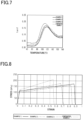
- a known method for evaluating the physical properties of the resin film 10 is a tensile test performed on a sample having a dumbbell shape. According to the tensile test, a stress-strain curve indicating the relationship between the stress applied to the sample and the strain of the sample when the stress is applied can be obtained.
- the tensile test is defined in JIS K 7161-1:2014.
- Fig. 4 shows an example of the stress-strain curve obtained from the tensile test on a sample formed from the resin film 10.
- the stress at the yield point A indicated by an arrow is the yield stress.
- the breaking point B indicated by an arrow is a point at which the sample is broken, and the stress at this point B is the breaking strength.
- the resin film 10 undergoes elastic deformation in the range including a point at which both the stress and strain are 0 and the other points at which both the stress and strain are smaller than those at the yield point A, with the stress and strain being proportional to each other in the range.
- the resin film tends to be harder, and as the slope of the stress-strain curve is smaller, the resin film tends to be softer.
- the yield point A is the first part of the stress-strain curve in which the strain increases without increasing the stress.
- the area surrounded by the curve represents the ability of the resin film to absorb impact energy. As the area surrounded by the stress-strain curve is smaller, the resin film tends to be more brittle, that is, have lower tenacity. In contrast, as the area surrounded by the stress-strain curve is larger, the resin film tends to be less brittle, that is, have higher tenacity.
- the resin film 10 satisfies the following condition 1.
- the yield stress of the resin film 10 in the flow direction is 109 MPa or more and 117 MPa or less.
- the resin film 10 tends to be harder and more brittle as the yield stress is higher, and tends to be softer and have higher tenacity as the yield stress is lower.
- a gas barrier layer 11 made of an inorganic material that tends to be harder than the resin film 10 is bonded to the resin film 10.
- the stress acting on the gas barrier layer 11 be transferred from the gas barrier layer 11 to the resin film 10. That is, it is preferable that the resin film 10 is soft and has high tenacity so that the stress acting on the gas barrier layer 11 is consumed inside the resin film 10.
- the yield stress of the resin film 10 is excessively small, plastic deformation that causes defects in the gas barrier layer 11 is likely to occur in the resin film 10; thus, it is preferable that the resin film 10 has a predetermined hardness.
- a resin film 10 that satisfies condition 1 is soft enough not to become excessively brittle, and is hard enough to prevent excessive plastic deformation. Therefore, when the resin film 10 is used in the laminate 20 for forming the packaging body 30, it is possible to prevent the occurrence of defects in the gas barrier layer 11 formed on the resin film 10, and thus suppress reduction in gas barrier performance of the laminate 20 caused by the defects.
- a roll-to-roll apparatus is used. While the laminate 20 is carried by the roll-to-roll apparatus, the laminate 20 is subjected to treatment for forming the packaging body 30.
- the laminate 20 is carried by the roll-to-roll apparatus along the flow direction of the resin film 10.
- the laminate 20 is carried by the roll-to-roll apparatus while being stretched along the flow direction of the resin film 10.
- the resin film 10 is stretched along the flow direction with a stress that does not cause the laminate 20 to loosen or bend, while the laminate 20 can be carried and the packaging body 30 formed using the laminate 20 can be prevented from being wrinkled.
- the application and release of an external force that bends the packaging body 30 are repeated.
- the direction in which the external force due to shaking is applied, and the direction in which expansion and contraction are repeated by the application and release of the external force are approximately specified based on the structure of the packaging body 30.
- the yield stress of the resin film 10 in the flow direction is 109 MPa or more and 117 MPa or less, it is possible to achieve a sufficiently large yield stress in order to suppress plastic deformation of the resin film 10 caused by stress applied to the laminate 20 when the laminate 20 is carried. Further, by aligning the direction in which the external force due to shaking is applied with the flow direction of the resin film 10, it is possible to suppress plastic deformation of the resin film 10 and associated reduction in the barrier performance.
- the resin film 10 preferably satisfies the following condition 2 in addition to condition 1 described above.
- the resin film 10 has the yield point at a strain of less than 0.1.
- a stress higher than the yield stress at the yield point A is applied, the state in which only the strain increases is released, and the strain increases again according to the increase in stress.
- the increase in strain is almost proportional to the increase in stress.
- the slope of the stress-strain curve after the yield point A is greater, the resin film 10 is harder, and the difference between the strain at the yield point A and the strain at the breaking point B tends to be smaller.
- the resin film 10 is softer, and the difference between the strain at the yield point A and the strain at the breaking point B tends to be greater.
- the resin film 10 often has the breaking point B at a strain exceeding 0.4, and the tendency in the rigidity of the resin film 10 can be grasped by the slope at a strain of 0.4 or less.
- the resin film 10 preferably satisfies the following condition 3 in addition to condition 1 described above.
- the resin film 10 more preferably satisfies the following condition 3 in addition to conditions 1 and 2 described above.
- the resin film 10 tends to be harder as the breaking strength is higher, and tends to have higher tenacity as the breaking strength is lower. Therefore, if the breaking strength is excessively high, the stress value at which the resin film 10 breaks tends to increase, whereas the strain that the resin film 10 can withstand tends to decrease. In contrast, if the breaking strength is excessively small, the strain that the resin film 10 can withstand increases, whereas the stress value at which the resin film 10 breaks tends to decrease.
- condition 3 if the resin film 10 satisfies condition 3, either the stress or strain that the resin film 10 can withstand without breaking can be prevented from becoming excessively low. This allows the resin film 10 to be not easily broken. As a result, it is possible to prevent the occurrence of defects in the vapor deposition layer caused by breakage of the resin film 10.
- the yield stress, slope after yield, and breaking strength in the resin film 10 can be adjusted, for example, by the temperature at which the resin film 10 is extruded, the temperature at which the precursor of the extruded resin film 10 is cooled, the speed of cooling the precursor, and the draw ratio of the resin film 10. Further, the yield stress, slope after yield, and breaking strength in the resin film 10 can be adjusted, for example, by the ratio of isophthalic acid in the total dicarboxylic acid units contained in the resin film 10.
- the yield stress, slope after yield, and breaking strength can be increased by increasing the temperature of extrusion. Further, the yield stress, slope after yield, and breaking strength can be reduced by reducing the temperature at which the precursor of the extruded resin film 10 is cooled. Further, the yield stress, slope after yield, and breaking strength can be reduced by increasing the speed of cooling the precursor. Further, the yield stress, slope after yield, and breaking strength can be reduced by increasing the draw ratio of the resin film 10. Further, the yield stress, slope after yield, and breaking strength can be reduced by increasing the ratio of isophthalic acid in the total dicarboxylic acid units contained in the resin film 10.
- a resin film 10 of Example 1 having a thickness of 12 ⁇ m.
- the three resin layers having the same composition were formed from virgin PET and recycled PET recycled by mechanical recycling.
- the mass of the recycled PET was set to 80% relative to the total mass of the resin film, and the mass of the virgin PET was set to 20% relative to the total mass of the resin film.
- the first resin layers were formed from recycled PET recycled by chemical recycling.
- the second resin layer was formed by mixing recycled PET recycled by mechanical recycling and recycled PET recycled by chemical recycling.
- the mass of the recycled PET recycled by mechanical recycling was set to 80% relative to the total mass of the second resin layer, and the mass of the recycled PET recycled by chemical recycling was set to 20% relative to the total mass of the second resin layer.
- the mass of the recycled PET was set to 100% relative to the total mass of the resin film 10.
- the first resin layers were formed from virgin PET.
- the second resin layer was formed from recycled PET recycled by chemical recycling.
- the mass of the recycled PET was set to 70% relative to the total mass of the resin film 10.
- a single resin layer was formed using virgin PET to obtain a resin film 10 of Comparative Example 1 having a thickness of 12 ⁇ m.
- the mass of recycled PET was set to 0% relative to the total mass of the resin film.
- a vapor deposition layer formed from aluminum oxide and having a thickness of 10 nm was laminated on the resin film 10 of Example 1 using a vacuum deposition method. Further, a coating film having a thickness of 0.3 ⁇ m was formed by gravure coating on the vapor deposition layer.
- a first solution was prepared by adding hydrochloric acid to tetraethoxysilane, and stirring the mixture for 30 minutes to hydrolyze the tetraethoxysilane, and a second solution was prepared by dissolving polyvinyl alcohol in a mixed solution of water and isopropyl alcohol. Then, 60 parts by mass of the first solution and 40 parts by mass of the second solution were mixed to prepare a coating agent.
- the coating agent was applied to the vapor deposition layer using a bar coater, and then dried with a dryer at 120°C for 1 minute, thereby forming a coating film.
- a laminate of Example 4 comprising the resin film 10 and a gas barrier layer 11 containing the vapor deposition layer and the coating film was obtained.
- a laminate of Comparative Example 2 was obtained using the same materials and the same method as in Example 4, except that in Example 4, the resin film 10 of Example 1 was changed to the resin film of Comparative Example 1. As a result, a laminate of Comparative Example 2 comprising the resin film of Comparative Example 1 and a gas barrier layer 11 containing a resin layer and a coating film was obtained.
- Strip-shaped samples were produced from the resin films of the Examples and Comparative Examples.
- the length of each sample was 20 mm, and the width of each sample was 10 mm.
- the flow direction (MD direction) in the formation of the resin film was set as the length direction of the sample.
- DMA7100 dynamic mechanical analyzer
- the storage modulus G1 and loss modulus G2 of each sample were measured, and tan ⁇ was calculated.
- the measurement conditions are as follows.
- Heating conditions heating rate: 2°C/min : heating temperature: 30°C to 180°C
- a tensile test was performed on the samples by a method according to JIS K 7161-1:2014. At this time, each sample was fixed to the compact table-top tester, and the marked lines were held by the extensometer. The test speed was set to 300 mm/min. For each of Examples 1 to 3 and Comparative Example 1, a stress-strain curve was created based on the results of the tensile test on one sample. The yield stress, breaking strength, and slope after yield at a strain of 0.2 or more and 0.4 or less were obtained from each stress-strain curve.
- the Gelboflex test of each sample was carried out using a flexibility evaluation device (Gelbo Flex Tester, produced by Tester Sangyo Co., Ltd.). At this time, each sample was attached to the fixed head of the flexibility evaluation device so that the sample had a cylindrical shape. Specifically, both ends of each sample were held by the fixed head, and the initial gripping interval was set to 175 mm. Then, while setting the stroke to 87.5 mm and the twist to 440°, reciprocating motion was performed by twisting and untwisting each sample 10 times at a speed of 40 times/min. At this time, the samples used had a rectangular shape of A4 size, that is, 210 mm wide and 297 mm long.
- the oxygen permeability of each sample before and after the Gelboflex test was measured using an oxygen permeability tester (OX-TRAN 2/20, produced by Mocon). At this time, a method according to JIS K 7126-2:2006 and ASTM D3985-81 was used. Further, the temperature was set to 30°C, and the relative humidity was set to 70%. The unit of the measured value of oxygen permeability was set as [cm 3 (STP)/m 2 ⁇ day ⁇ MPa].
- the moisture permeability of each sample before and after the Gelboflex test was measured using a moisture permeability tester (PERMATRAN-W 3/31, produced by Mocon). At this time, the measurement was carried out at a temperature of 40°C and a relative humidity of 90%.
- the measurement method used was a method according to JIS K 7129-2:2019 and ASTM F1249-90.
- the unit of the measured value of moisture permeability was set as [g(STP)/m 2 ⁇ day].
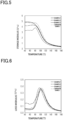
- Figs. 5 to 7 show curves obtained by measuring the dynamic moduli of the resin films of the Examples and Comparative Example.
- Fig. 5 shows storage modulus curves
- Fig. 6 shows loss modulus curves
- Fig. 7 shows loss tangent curves. The measurement of dynamic moduli was performed on three samples for each Example and Comparative Example.
- the curves shown in Figs. 5 to 7 are representative curves among the curves obtained by measurement on the three samples.
- Table 1 shows the analysis results of storage modulus, loss modulus, and tan ⁇ of the resin films of the Examples and Comparative Example. Each value in the analysis results is the average of the measured values obtained from the three samples.
- Analysis values of the storage modulus are transition temperature T1 in the storage modulus curve and storage modulus G1 at the transition temperature T1.
- the transition temperature T1 was set as the temperature at the intersection point of an approximate straight line of the glass region on the low-temperature side of the inflection point in the storage modulus curve, and an approximate straight line of the transition region on the high-temperature side of the inflection point.
- the approximate straight line on the low-temperature side was created by approximating, to a straight line, the inflection point and a group of measurement points from a point about 10 degrees lower than the inflection point to a point about 5 degrees lower than the inflection point.
- the approximate straight line on the high-temperature side was created by approximating, to a straight line, the inflection point and a group of measurement points from a point about 5 degrees higher than the inflection point to a point about 10 degrees higher than the inflection point.
- Analysis values of the loss modulus are temperature T2 and loss modulus G2 at the peak position in the loss modulus curve.
- Analysis values of the tan ⁇ are temperature T3 and tan ⁇ values at the peak position in the loss tangent curve.
- the transition temperature T1 in the storage modulus curve is 80°C or higher and 88°C or lower, and the storage modulus G1 at the transition temperature T1 is 3.8 GPa or more and 4.1 GPa or less.
- the storage modulus G1 of Comparative Example 1 which does not contain recycled PET, is larger than 4.1 GPa. That is, it is suggested that the nature of the resin film of the Comparative Example as an elastic body is stronger than that of the resin films of Examples 1 to 3.
- the temperature T2 at the peak position in the loss modulus curve is 95°C or higher and 102°C or lower, and the loss modulus G2 at the peak position is 0.30 GPa or more and 0.37 GPa or less.
- the temperature T2 of Comparative Example 1 is higher than 102°C. That is, it is suggested that the resin film of Comparative Example 1 is less likely to exhibit flexibility associated with viscosity in the low-temperature region.
- the loss modulus G2 at the peak position in Comparative Example 1 is larger than 0.37; however, when compared with the differences in the storage modulus G1 between the Examples and Comparative Example, the differences in the loss modulus G2 are smaller. It is thus hard to say that the nature as a viscous body is noticeably stronger in the Comparative Example.
- the temperature T3 at the peak position in the loss tangent curve is 108°C or higher and 115°C or lower, and the tan ⁇ at the peak position is 0.160 or more and 0.190 or less.
- the tan ⁇ at the peak position of the Comparative Example is less than 0.160. That is, it is suggested that compared with Examples 1 to 3, the nature as a viscous body relative to the nature as an elastic body is smaller in the Comparative Example, and that the percentage of the contribution of viscosity in response to the external force is smaller. Further, the temperature T3 of the Comparative Example is higher than 115°C, which suggests that the resin film of the Comparative Example is less likely to exhibit flexibility in the low-temperature region.
- Fig. 8 shows an example of the stress-strain curve obtained from each resin film.
- the yield stress was as shown in the following Table 2
- the slope after yield was as shown in the following Table 3
- the breaking strength was as shown in the following Table 4.
- the pinhole resistance due to vibration during transportation or the like which is simulated by the Gelboflex test, increases. This is considered to suppress the increase in the numerical values of oxygen permeability and moisture permeability, that is, reduction in the gas barrier performance.
Landscapes
- Chemical & Material Sciences (AREA)
- Engineering & Computer Science (AREA)
- Health & Medical Sciences (AREA)
- Chemical Kinetics & Catalysis (AREA)
- Medicinal Chemistry (AREA)
- Polymers & Plastics (AREA)
- Organic Chemistry (AREA)
- Manufacturing & Machinery (AREA)
- Materials Engineering (AREA)
- Mechanical Engineering (AREA)
- Inorganic Chemistry (AREA)
- Laminated Bodies (AREA)
Applications Claiming Priority (5)
| Application Number | Priority Date | Filing Date | Title |
|---|---|---|---|
| JP2020118818A JP7592994B2 (ja) | 2020-07-09 | 2020-07-09 | 樹脂フィルム、積層体、および、包装袋 |
| JP2020118819A JP7600553B2 (ja) | 2020-07-09 | 2020-07-09 | 樹脂フィルム、積層体、および、包装袋 |
| JP2020118820A JP7600554B2 (ja) | 2020-07-09 | 2020-07-09 | 樹脂フィルム、積層体、および、包装袋 |
| JP2020122415A JP7592998B2 (ja) | 2020-07-16 | 2020-07-16 | 樹脂フィルム、積層体、および、包装体 |
| PCT/JP2021/026011 WO2022009989A1 (ja) | 2020-07-09 | 2021-07-09 | 樹脂フィルム、積層体、および、包装体 |
Publications (2)
| Publication Number | Publication Date |
|---|---|
| EP4180352A1 true EP4180352A1 (de) | 2023-05-17 |
| EP4180352A4 EP4180352A4 (de) | 2024-01-03 |
Family
ID=79552559
Family Applications (1)
| Application Number | Title | Priority Date | Filing Date |
|---|---|---|---|
| EP21837239.9A Pending EP4180352A4 (de) | 2020-07-09 | 2021-07-09 | Harzfolie, laminat und verpackungskörper |
Country Status (4)
| Country | Link |
|---|---|
| US (1) | US12497493B2 (de) |
| EP (1) | EP4180352A4 (de) |
| CN (1) | CN115720549A (de) |
| WO (1) | WO2022009989A1 (de) |
Families Citing this family (2)
| Publication number | Priority date | Publication date | Assignee | Title |
|---|---|---|---|---|
| US20200114633A1 (en) | 2018-10-12 | 2020-04-16 | Berry Global, Inc. | Machine direction-oriented polymeric film, and method of making the machine direction-oriented polymeric film |
| TWI765551B (zh) * | 2021-01-29 | 2022-05-21 | 南亞塑膠工業股份有限公司 | 可熱封聚酯膜 |
Family Cites Families (14)
| Publication number | Priority date | Publication date | Assignee | Title |
|---|---|---|---|---|
| JP3133665B2 (ja) * | 1995-12-28 | 2001-02-13 | 積水化成品工業株式会社 | 果実収納用容器 |
| JP2008049605A (ja) * | 2006-08-25 | 2008-03-06 | Toppan Printing Co Ltd | レトルト適性を付与した透明積層体 |
| JP6073549B2 (ja) * | 2011-12-16 | 2017-02-01 | コニカミノルタ株式会社 | ガスバリアーフィルム、電子機器及びガスバリアーフィルムの製造方法 |
| JP6036099B2 (ja) | 2012-09-27 | 2016-11-30 | 東洋紡株式会社 | Petボトル再生原料を使用した二軸配向ポリエステルフィルム |
| JP6210242B2 (ja) | 2014-03-26 | 2017-10-11 | 東洋紡株式会社 | 積層フィルム |
| JP6944656B2 (ja) * | 2017-07-13 | 2021-10-06 | 大日本印刷株式会社 | 積層体 |
| JP7202119B2 (ja) | 2017-10-30 | 2023-01-11 | 藤森工業株式会社 | ラミネート積層体、および、そのラミネート積層体によって形成される包装袋 |
| MX2020004433A (es) * | 2017-10-31 | 2020-11-06 | Flex Films Usa Inc | Peliculas termoplasticas de baja huella de carbono que incluyen materiales reciclados. |
| WO2019189221A1 (ja) * | 2018-03-27 | 2019-10-03 | 大日本印刷株式会社 | 電池用包装材料用ポリエチレンテレフタレートフィルム、電池用包装材料、電池用包装材料の製造方法及び電池 |
| JP6519899B2 (ja) * | 2018-06-04 | 2019-05-29 | 大日本印刷株式会社 | ポリエステルフィルム |
| JP2020032596A (ja) | 2018-08-29 | 2020-03-05 | 凸版印刷株式会社 | 真空断熱材用外装材及び真空断熱材 |
| JP7434767B2 (ja) * | 2018-09-19 | 2024-02-21 | 大日本印刷株式会社 | ガスバリア性蒸着フィルム、および該ガスバリア性蒸着フィルムを用いた積層体、包装材料、包装体 |
| JP7333012B2 (ja) * | 2018-10-19 | 2023-08-24 | 大日本印刷株式会社 | 包装材料 |
| JP2020070429A (ja) | 2018-10-31 | 2020-05-07 | 大日本印刷株式会社 | 酸素プラズマ処理樹脂フィルム、ガスバリア性蒸着フィルム及び該ガスバリア性蒸着フィルムを用いたガスバリア性積層体、ガスバリア性包装材料、ガスバリア性包装体、ガスバリア性包装袋、及びそれらの製造方法 |
-
2021
- 2021-07-09 WO PCT/JP2021/026011 patent/WO2022009989A1/ja not_active Ceased
- 2021-07-09 EP EP21837239.9A patent/EP4180352A4/de active Pending
- 2021-07-09 CN CN202180044317.3A patent/CN115720549A/zh active Pending
-
2023
- 2023-01-03 US US18/149,343 patent/US12497493B2/en active Active
Also Published As
| Publication number | Publication date |
|---|---|
| EP4180352A4 (de) | 2024-01-03 |
| US12497493B2 (en) | 2025-12-16 |
| WO2022009989A1 (ja) | 2022-01-13 |
| US20230139647A1 (en) | 2023-05-04 |
| CN115720549A (zh) | 2023-02-28 |
Similar Documents
| Publication | Publication Date | Title |
|---|---|---|
| JP6350276B2 (ja) | 二軸配向ポリアミド系樹脂フィルム | |
| US12497493B2 (en) | Resin film, laminate, and packaging body | |
| JP2025037977A (ja) | 樹脂フィルム、積層体、および、包装袋 | |
| WO2020203106A1 (ja) | ポリエステルフィルム及びその製造方法 | |
| EP3831599A1 (de) | Laminat und verpackungsbeutel damit | |
| EP3590706A1 (de) | Verbundfolie | |
| TW202313806A (zh) | 熱收縮性膜及其製造方法 | |
| KR20090062882A (ko) | 열수축성 적층필름 및 이를 기재로 이용한 열수축성 라벨 | |
| WO2019187694A1 (ja) | ポリエステルフィルムロール | |
| JP2025028092A (ja) | 樹脂フィルム、積層体、および、包装袋 | |
| JP2025108617A (ja) | 樹脂フィルム、包装体用積層体及び包装体 | |
| US20230391967A1 (en) | Polyester-based shrink film | |
| EP4461527A1 (de) | Harzfolie, laminat und verpackung | |
| JP7592998B2 (ja) | 樹脂フィルム、積層体、および、包装体 | |
| JP7592994B2 (ja) | 樹脂フィルム、積層体、および、包装袋 | |
| JP7604956B2 (ja) | 小容量液剤用外装袋、および小容量液剤用外装袋の製造方法 | |
| CN117881538A (zh) | 双轴拉伸聚酰胺膜和包装材料 | |
| JP2007203652A (ja) | ニ軸延伸ポリエステルフイルムおよび包装体 | |
| JP7631909B2 (ja) | 包装体用積層体、包装体、及び、包装体用樹脂フィルム | |
| JP7830374B2 (ja) | スタンディングパウチ及び包装物品 | |
| JP2023039268A (ja) | 包装袋 | |
| JP7619109B2 (ja) | 包装体用積層体、包装体、および、包装体用樹脂フィルム | |
| JP2005074642A (ja) | ガスバリア性積層体 | |
| JP2023008176A (ja) | 包装袋 | |
| JP2019171587A (ja) | ポリエステルフィルムおよびガスバリア性積層フィルム |
Legal Events
| Date | Code | Title | Description |
|---|---|---|---|
| STAA | Information on the status of an ep patent application or granted ep patent |
Free format text: STATUS: THE INTERNATIONAL PUBLICATION HAS BEEN MADE |
|
| PUAI | Public reference made under article 153(3) epc to a published international application that has entered the european phase |
Free format text: ORIGINAL CODE: 0009012 |
|
| STAA | Information on the status of an ep patent application or granted ep patent |
Free format text: STATUS: REQUEST FOR EXAMINATION WAS MADE |
|
| 17P | Request for examination filed |
Effective date: 20230113 |
|
| AK | Designated contracting states |
Kind code of ref document: A1 Designated state(s): AL AT BE BG CH CY CZ DE DK EE ES FI FR GB GR HR HU IE IS IT LI LT LU LV MC MK MT NL NO PL PT RO RS SE SI SK SM TR |
|
| DAV | Request for validation of the european patent (deleted) | ||
| DAX | Request for extension of the european patent (deleted) | ||
| A4 | Supplementary search report drawn up and despatched |
Effective date: 20231130 |
|
| RIC1 | Information provided on ipc code assigned before grant |
Ipc: C08J 7/04 20200101ALI20231124BHEP Ipc: B32B 27/08 20060101ALI20231124BHEP Ipc: C08J 7/048 20200101ALI20231124BHEP Ipc: C08J 5/18 20060101ALI20231124BHEP Ipc: B32B 27/36 20060101ALI20231124BHEP Ipc: B32B 27/00 20060101ALI20231124BHEP Ipc: B32B 9/00 20060101ALI20231124BHEP Ipc: B32B 7/027 20190101ALI20231124BHEP Ipc: B65D 65/40 20060101AFI20231124BHEP |