EP4180381A1 - Antitropfsystem für eine fülldüse mit einer membran - Google Patents
Antitropfsystem für eine fülldüse mit einer membran Download PDFInfo
- Publication number
- EP4180381A1 EP4180381A1 EP22164094.9A EP22164094A EP4180381A1 EP 4180381 A1 EP4180381 A1 EP 4180381A1 EP 22164094 A EP22164094 A EP 22164094A EP 4180381 A1 EP4180381 A1 EP 4180381A1
- Authority
- EP
- European Patent Office
- Prior art keywords
- membrane
- nozzle
- head
- machining
- product
- Prior art date
- Legal status (The legal status is an assumption and is not a legal conclusion. Google has not performed a legal analysis and makes no representation as to the accuracy of the status listed.)
- Withdrawn
Links
- 239000012528 membrane Substances 0.000 title claims abstract description 63
- 238000003754 machining Methods 0.000 claims abstract description 20
- 239000012190 activator Substances 0.000 claims description 7
- 230000000903 blocking effect Effects 0.000 claims description 2
- 230000000295 complement effect Effects 0.000 claims description 2
- 230000037431 insertion Effects 0.000 claims 1
- 238000003780 insertion Methods 0.000 claims 1
- 238000002347 injection Methods 0.000 abstract description 3
- 239000007924 injection Substances 0.000 abstract description 3
- 239000007788 liquid Substances 0.000 description 3
- 238000006073 displacement reaction Methods 0.000 description 2
- 239000013013 elastic material Substances 0.000 description 2
- 235000011837 pasties Nutrition 0.000 description 2
- 230000000284 resting effect Effects 0.000 description 2
- 238000004140 cleaning Methods 0.000 description 1
- 230000000694 effects Effects 0.000 description 1
- 230000014759 maintenance of location Effects 0.000 description 1
- 230000004048 modification Effects 0.000 description 1
- 238000012986 modification Methods 0.000 description 1
- 230000002093 peripheral effect Effects 0.000 description 1
- 238000007789 sealing Methods 0.000 description 1
Images


Classifications
-
- B—PERFORMING OPERATIONS; TRANSPORTING
- B67—OPENING, CLOSING OR CLEANING BOTTLES, JARS OR SIMILAR CONTAINERS; LIQUID HANDLING
- B67C—CLEANING, FILLING WITH LIQUIDS OR SEMILIQUIDS, OR EMPTYING, OF BOTTLES, JARS, CANS, CASKS, BARRELS, OR SIMILAR CONTAINERS, NOT OTHERWISE PROVIDED FOR; FUNNELS
- B67C3/00—Bottling liquids or semiliquids; Filling jars or cans with liquids or semiliquids using bottling or like apparatus; Filling casks or barrels with liquids or semiliquids
- B67C3/02—Bottling liquids or semiliquids; Filling jars or cans with liquids or semiliquids using bottling or like apparatus
- B67C3/22—Details
- B67C3/26—Filling-heads; Means for engaging filling-heads with bottle necks
- B67C3/2608—Filling-heads; Means for engaging filling-heads with bottle necks comprising anti-dripping means
-
- B—PERFORMING OPERATIONS; TRANSPORTING
- B05—SPRAYING OR ATOMISING IN GENERAL; APPLYING FLUENT MATERIALS TO SURFACES, IN GENERAL
- B05B—SPRAYING APPARATUS; ATOMISING APPARATUS; NOZZLES
- B05B1/00—Nozzles, spray heads or other outlets, with or without auxiliary devices such as valves, heating means
- B05B1/34—Nozzles, spray heads or other outlets, with or without auxiliary devices such as valves, heating means designed to influence the nature of flow of the liquid or other fluent material, e.g. to produce swirl
-
- B—PERFORMING OPERATIONS; TRANSPORTING
- B65—CONVEYING; PACKING; STORING; HANDLING THIN OR FILAMENTARY MATERIAL
- B65B—MACHINES, APPARATUS OR DEVICES FOR, OR METHODS OF, PACKAGING ARTICLES OR MATERIALS; UNPACKING
- B65B39/00—Nozzles, funnels or guides for introducing articles or materials into containers or wrappers
-
- F—MECHANICAL ENGINEERING; LIGHTING; HEATING; WEAPONS; BLASTING
- F16—ENGINEERING ELEMENTS AND UNITS; GENERAL MEASURES FOR PRODUCING AND MAINTAINING EFFECTIVE FUNCTIONING OF MACHINES OR INSTALLATIONS; THERMAL INSULATION IN GENERAL
- F16K—VALVES; TAPS; COCKS; ACTUATING-FLOATS; DEVICES FOR VENTING OR AERATING
- F16K7/00—Diaphragm valves or cut-off apparatus, e.g. with a member deformed, but not moved bodily, to close the passage ; Pinch valves
- F16K7/12—Diaphragm valves or cut-off apparatus, e.g. with a member deformed, but not moved bodily, to close the passage ; Pinch valves with flat, dished, or bowl-shaped diaphragm
- F16K7/14—Diaphragm valves or cut-off apparatus, e.g. with a member deformed, but not moved bodily, to close the passage ; Pinch valves with flat, dished, or bowl-shaped diaphragm arranged to be deformed against a flat seat
- F16K7/17—Diaphragm valves or cut-off apparatus, e.g. with a member deformed, but not moved bodily, to close the passage ; Pinch valves with flat, dished, or bowl-shaped diaphragm arranged to be deformed against a flat seat the diaphragm being actuated by fluid pressure
Definitions
- the present invention relates to an anti-drip system for a dosing machine, of the kind used to enable the passage of a liquid or pasty product to a container, which incorporates a nozzle with a membrane.
- the purpose of the invention is to ensure a correct dosage of the amount of product, limited by the dosing device on the container, preventing undesirable drips and splashes and performing it in the shortest time possible, in addition to reducing the wear of the membranes.
- Bolt systems present problems in cleaning the internal rod and are not suitable for low-viscosity products, as they present dripping problems that increase with the wear of the elements.
- Membrane systems present problems by generating splashes and/or drips in the containers when the opening and closing of the conduit towards the container occurs.
- the membrane When working with sticky products, the membrane can adhere to the surface of the nozzle when the closing occurs. When the product is pushed towards the nozzle, the membrane does not open, causing an overpressure that opens the membrane abruptly, generating splashes on the container.
- the present invention solves problems of this type, preventing undesired drips and splashes, also providing two additional advantages, such as the fact that the dosage is carried out in the shortest time possible and the wear of the membranes is reduced.
- the present invention describes an anti-drip system for a nozzle with a membrane for a dosing machine for liquid or viscous products.
- the anti-drip system comprises a nozzle with a head that incorporates holes, a membrane located on the head, a block with a fastening to fasten the nozzle, an opening for the connection of an inlet conduit of product from a dosing system, a retention means for retaining the membrane against a closing plate that incorporates a machining that enables a space with the nozzle for the expansion of the membrane and a channel, which passes through the support plate by the machining, and an activator bushing, connected to a pneumatic system, with a cannula inserted into the channel.
- the novelty of the anti-drip system consists of modifications made to the components to ensure that the movement of the membrane to be adjusted or removed from the nozzle is minimal and uniform for the entire membrane, without abruptness.
- the head of the nozzle has a domed configuration, while the membrane comprises a dome-shaped central portion complementary to the head of the nozzle.
- the machining of the top plate is domed.
- This configuration achieves that, when the dosing system is activated, the product presses on the membrane, which stretches minimally and uniformly until it contacts the machining, and that, once the product dosing is finished, the pneumatic system blows air through the cannula, pushing the membrane against the head and blocking the holes.
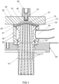
- the present invention relates to an anti-drip system for product dosing equipment for a nozzle (10) with a membrane (20).
- system of the invention comprises the following elements:
- the nozzle (10) has a cylindrical shape with a plurality of holes (11) passing through it longitudinally. In any case, it can also be single tube if the product to be dosed is very viscous.
- the nozzle has a dome-shaped head (12), a protrusion (13) to secure the membrane (2) and a recess (14) to seat an O-ring and ensure closure with the block (30).
- the membrane (20) comprises a flat ring (22) that has a peripheral projection (23) in the outermost area to ensure the securing thereof and a dome (21), in the interior area in the opposite direction to the projection (23).
- the block (30) has a hollow cylindrical shape and comprises an internal wall (32), an opening (34) intended to accommodate an inlet conduit of product that is injected from a dispensing device. It also comprises a groove (31) in the upper base, intended to house the projection (23) of the membrane (20).
- the closing plate (40) comprises a lower dome-shaped machining (41), and a channel (42) for the passage of the activator bushing (50).
- the activator bushing (50) is connected to pneumatic equipment and comprises a cannula (51) for the outlet of air located in the channel (42) of the closing plate (40).
- the support plate (60) is responsible for giving dimensional stability to the assembly, such that both the block (30) and the nozzle (10) sit on it.
- Figures 1 and 2 show the system of the invention assembled to the support plate (60).
- the projection (23) of the membrane (20) is intended to sit in the groove (31) of the block (30), such that a sealed joint can be achieved.
- the protrusion (13) of the nozzle (10) presses the flat ring (22) of the nozzle (10) against the closing plate (40) to reinforce the seal.
- the membrane (20) is made of an elastic material that also facilitates the extension movement to release the holes (11) for the transit of product.
- the opening (34) of the block (30) is intended to receive in a sealed manner an inlet conduit through which product is supplied from a dosing system.
- the activator bushing (50) for its part is coupled to the closing plate (40) with the cannula (51) inserted in the channel (42).
- the dosing system is in operation and has injected product through the inlet conduit, which accesses the block (30) through the opening (34) to flow through the gap enabled between the internal wall (32) of the block (30) and the nozzle (10) and be introduced through the holes (11) pushing the membrane (20) and separating it from the head (12) of the nozzle (10) until the dome (21) of the membrane (20) contacts the machining (41) of the closing plate (40) which is in the extended position.
- This is facilitated by the elasticity provided to the membrane (20) by the elastic material from which it is made.
- the movement of the membrane (20) to change from the resting position to being coupled in the machining (41) is minimal and uniform at all points of the membrane (20), maintaining a constant space for the passage of the product.
- the pneumatic system must be deactivated, enabling the outlet of the air located between the machining (41) of the closing plate (40) and the dome (21) of the membrane (20).
- the product enters the block (30) through the inlet conduit to flow through the gap enabled between the internal wall (32) of the block (30) and the nozzle (10) and move towards the holes (11) to exit through the other end towards a container enabled to be filled.
- the product injection is cut off and the pneumatic system is activated, creating pressure on the membrane (20) which not only helps it to return to the resting position on the head (12), but pushes it to plug the access to the holes (11).
- This domed configuration of the membrane (20) and the head (12) means that, even in the case of very sticky products causing the membrane (20) to adhere to the head (12), the pressure exerted by the product to separate the membrane (20) of the head (12) is carried out smoothly and continuously, without jolts, which prevents the product from pushing on the membrane (20) and splashes, making the opening immediate.
- the machining (41) also has a domed configuration, it causes the displacement of the membrane (20) to be minimal, performing a complete closure almost immediately and similarly for all points when stretched.
- the stretching caused is also reduced, extending the life of the membrane (20).
Landscapes
- Engineering & Computer Science (AREA)
- Mechanical Engineering (AREA)
- General Engineering & Computer Science (AREA)
- Physics & Mathematics (AREA)
- Fluid Mechanics (AREA)
- Infusion, Injection, And Reservoir Apparatuses (AREA)
- Coating Apparatus (AREA)
Applications Claiming Priority (1)
| Application Number | Priority Date | Filing Date | Title |
|---|---|---|---|
| ES202131048A ES2940738B2 (es) | 2021-11-10 | 2021-11-10 | Sistema antigoteo de boquilla con membrana |
Publications (1)
| Publication Number | Publication Date |
|---|---|
| EP4180381A1 true EP4180381A1 (de) | 2023-05-17 |
Family
ID=80933259
Family Applications (1)
| Application Number | Title | Priority Date | Filing Date |
|---|---|---|---|
| EP22164094.9A Withdrawn EP4180381A1 (de) | 2021-11-10 | 2022-03-24 | Antitropfsystem für eine fülldüse mit einer membran |
Country Status (2)
| Country | Link |
|---|---|
| EP (1) | EP4180381A1 (de) |
| ES (1) | ES2940738B2 (de) |
Cited By (1)
| Publication number | Priority date | Publication date | Assignee | Title |
|---|---|---|---|---|
| CN117228611A (zh) * | 2023-11-16 | 2023-12-15 | 四川嘉智生态科技有限公司 | 一种多品种液体分装机 |
Citations (2)
| Publication number | Priority date | Publication date | Assignee | Title |
|---|---|---|---|---|
| DE102008028772A1 (de) * | 2008-06-17 | 2009-12-24 | Hansen, Bernd, Dipl.-Ing. | Vorrichtung zum Befüllen von Behältnissen |
| GB2569364A (en) * | 2017-12-15 | 2019-06-19 | Elopak Gmbh | Improved filling device |
Family Cites Families (4)
| Publication number | Priority date | Publication date | Assignee | Title |
|---|---|---|---|---|
| FR2654649B1 (fr) * | 1989-11-22 | 1992-03-27 | Erca Holding | Buse de distribution a membrane pour produits liquides ou pateux et membrane utilisable dans une telle buse. |
| AR001305A1 (es) * | 1996-11-29 | 1997-10-08 | Daniel Osvaldo Portugues | Mejoras en boquillas, de salida de un fluido a presión que incluye una membrana flexible, obturadoradel canal de salida de dicha boquilla. |
| DE102008028215A1 (de) * | 2008-06-06 | 2009-12-10 | Hansgrohe Ag | Brausekopf |
| PL3280539T3 (pl) * | 2015-04-09 | 2019-11-29 | Husqvarna Ab | Głowica natryskowa i aparat natryskowy |
-
2021
- 2021-11-10 ES ES202131048A patent/ES2940738B2/es not_active Expired - Fee Related
-
2022
- 2022-03-24 EP EP22164094.9A patent/EP4180381A1/de not_active Withdrawn
Patent Citations (2)
| Publication number | Priority date | Publication date | Assignee | Title |
|---|---|---|---|---|
| DE102008028772A1 (de) * | 2008-06-17 | 2009-12-24 | Hansen, Bernd, Dipl.-Ing. | Vorrichtung zum Befüllen von Behältnissen |
| GB2569364A (en) * | 2017-12-15 | 2019-06-19 | Elopak Gmbh | Improved filling device |
Cited By (2)
| Publication number | Priority date | Publication date | Assignee | Title |
|---|---|---|---|---|
| CN117228611A (zh) * | 2023-11-16 | 2023-12-15 | 四川嘉智生态科技有限公司 | 一种多品种液体分装机 |
| CN117228611B (zh) * | 2023-11-16 | 2024-01-19 | 四川嘉智生态科技有限公司 | 一种多品种液体分装机 |
Also Published As
| Publication number | Publication date |
|---|---|
| ES2940738B2 (es) | 2023-09-12 |
| ES2940738A1 (es) | 2023-05-10 |
Similar Documents
| Publication | Publication Date | Title |
|---|---|---|
| US4607764A (en) | Fluent product extraction system | |
| US4410108A (en) | Pressure-actuated valve for use with positive displacement filling machine | |
| US5271432A (en) | Adjustable valve and dispenser provided with a valve of this kind | |
| AU709501B2 (en) | Device for dispensing an air-liquid mixture, in particular foam, and operating unit intended therefor | |
| US7249694B2 (en) | Valve mechanism for tube-type fluid container | |
| EP1102707B1 (de) | Behälterventil | |
| JP2523431B2 (ja) | 二種類のクリ―ム状又はペ―スト状製品を貯蔵かつ分配する分配器を構成する内管及び該分配器 | |
| KR0172622B1 (ko) | 압력 분배 펌프 | |
| US20140231462A1 (en) | Metered dose squeeze dispenser | |
| JPH11165101A (ja) | 二種の生成物の施与装置 | |
| KR101969461B1 (ko) | 액상 내용물 토출 용기 | |
| CN112088048B (zh) | 喷雾容器 | |
| CN1265366A (zh) | 端部计量组件和装有这种端部计量组件的容器 | |
| US4709836A (en) | Fluid flow nozzle | |
| EP4180381A1 (de) | Antitropfsystem für eine fülldüse mit einer membran | |
| EP1102708B1 (de) | Behälterventil | |
| CA2318134A1 (en) | Self-closing manual dispenser | |
| JP2025060952A (ja) | 容器、封止体、及び製造方法 | |
| EP3431187B1 (de) | Vorrichtung zur abgabe mehrerer flüssigen produkte | |
| US10537903B2 (en) | Spray cap for container | |
| EP0770549B1 (de) | Dosierventil und Verfahren zum Dosieren von Flüssigkeiten | |
| RU2410306C2 (ru) | Вкладыш для контейнера, предназначенного для нескольких компонентов | |
| GB2360273A (en) | Liquid dosing device | |
| EP0682626A1 (de) | Behälterverschluss | |
| WO1999007614A1 (en) | Container |
Legal Events
| Date | Code | Title | Description |
|---|---|---|---|
| PUAI | Public reference made under article 153(3) epc to a published international application that has entered the european phase |
Free format text: ORIGINAL CODE: 0009012 |
|
| STAA | Information on the status of an ep patent application or granted ep patent |
Free format text: STATUS: REQUEST FOR EXAMINATION WAS MADE |
|
| 17P | Request for examination filed |
Effective date: 20221003 |
|
| AK | Designated contracting states |
Kind code of ref document: A1 Designated state(s): AL AT BE BG CH CY CZ DE DK EE ES FI FR GB GR HR HU IE IS IT LI LT LU LV MC MK MT NL NO PL PT RO RS SE SI SK SM TR |
|
| STAA | Information on the status of an ep patent application or granted ep patent |
Free format text: STATUS: THE APPLICATION IS DEEMED TO BE WITHDRAWN |
|
| 18D | Application deemed to be withdrawn |
Effective date: 20241001 |