EP4180602B1 - Penture dotée d'un élément de protection contre l'incendie - Google Patents
Penture dotée d'un élément de protection contre l'incendie Download PDFInfo
- Publication number
- EP4180602B1 EP4180602B1 EP22199232.4A EP22199232A EP4180602B1 EP 4180602 B1 EP4180602 B1 EP 4180602B1 EP 22199232 A EP22199232 A EP 22199232A EP 4180602 B1 EP4180602 B1 EP 4180602B1
- Authority
- EP
- European Patent Office
- Prior art keywords
- door
- receiving
- fire protection
- door hinge
- hinge
- Prior art date
- Legal status (The legal status is an assumption and is not a legal conclusion. Google has not performed a legal analysis and makes no representation as to the accuracy of the status listed.)
- Active
Links
Images


Classifications
-
- E—FIXED CONSTRUCTIONS
- E05—LOCKS; KEYS; WINDOW OR DOOR FITTINGS; SAFES
- E05D—HINGES OR SUSPENSION DEVICES FOR DOORS, WINDOWS OR WINGS
- E05D7/00—Hinges or pivots of special construction
-
- E—FIXED CONSTRUCTIONS
- E05—LOCKS; KEYS; WINDOW OR DOOR FITTINGS; SAFES
- E05D—HINGES OR SUSPENSION DEVICES FOR DOORS, WINDOWS OR WINGS
- E05D5/00—Construction of single parts, e.g. the parts for attachment
- E05D5/02—Parts for attachment, e.g. flaps
-
- E—FIXED CONSTRUCTIONS
- E05—LOCKS; KEYS; WINDOW OR DOOR FITTINGS; SAFES
- E05D—HINGES OR SUSPENSION DEVICES FOR DOORS, WINDOWS OR WINGS
- E05D3/00—Hinges with pins
- E05D3/06—Hinges with pins with two or more pins
-
- E—FIXED CONSTRUCTIONS
- E05—LOCKS; KEYS; WINDOW OR DOOR FITTINGS; SAFES
- E05D—HINGES OR SUSPENSION DEVICES FOR DOORS, WINDOWS OR WINGS
- E05D5/00—Construction of single parts, e.g. the parts for attachment
- E05D5/02—Parts for attachment, e.g. flaps
- E05D2005/0284—Parts for attachment, e.g. flaps for embedding in concrete or masonry
-
- E—FIXED CONSTRUCTIONS
- E05—LOCKS; KEYS; WINDOW OR DOOR FITTINGS; SAFES
- E05D—HINGES OR SUSPENSION DEVICES FOR DOORS, WINDOWS OR WINGS
- E05D3/00—Hinges with pins
- E05D3/06—Hinges with pins with two or more pins
- E05D3/16—Hinges with pins with two or more pins with seven parallel pins and four arms
-
- E—FIXED CONSTRUCTIONS
- E05—LOCKS; KEYS; WINDOW OR DOOR FITTINGS; SAFES
- E05D—HINGES OR SUSPENSION DEVICES FOR DOORS, WINDOWS OR WINGS
- E05D3/00—Hinges with pins
- E05D3/06—Hinges with pins with two or more pins
- E05D3/18—Hinges with pins with two or more pins with sliding pins or guides
- E05D3/186—Scissors hinges, with two crossing levers and five parallel pins
-
- E—FIXED CONSTRUCTIONS
- E05—LOCKS; KEYS; WINDOW OR DOOR FITTINGS; SAFES
- E05Y—INDEXING SCHEME ASSOCIATED WITH SUBCLASSES E05D AND E05F, RELATING TO CONSTRUCTION ELEMENTS, ELECTRIC CONTROL, POWER SUPPLY, POWER SIGNAL OR TRANSMISSION, USER INTERFACES, MOUNTING OR COUPLING, DETAILS, ACCESSORIES, AUXILIARY OPERATIONS NOT OTHERWISE PROVIDED FOR, APPLICATION THEREOF
- E05Y2600/00—Mounting or coupling arrangements for elements provided for in this subclass
- E05Y2600/40—Mounting location; Visibility of the elements
- E05Y2600/41—Concealed
-
- E—FIXED CONSTRUCTIONS
- E05—LOCKS; KEYS; WINDOW OR DOOR FITTINGS; SAFES
- E05Y—INDEXING SCHEME ASSOCIATED WITH SUBCLASSES E05D AND E05F, RELATING TO CONSTRUCTION ELEMENTS, ELECTRIC CONTROL, POWER SUPPLY, POWER SIGNAL OR TRANSMISSION, USER INTERFACES, MOUNTING OR COUPLING, DETAILS, ACCESSORIES, AUXILIARY OPERATIONS NOT OTHERWISE PROVIDED FOR, APPLICATION THEREOF
- E05Y2800/00—Details, accessories and auxiliary operations not otherwise provided for
- E05Y2800/25—Emergency conditions
- E05Y2800/252—Emergency conditions the elements functioning only in case of emergency
-
- E—FIXED CONSTRUCTIONS
- E05—LOCKS; KEYS; WINDOW OR DOOR FITTINGS; SAFES
- E05Y—INDEXING SCHEME ASSOCIATED WITH SUBCLASSES E05D AND E05F, RELATING TO CONSTRUCTION ELEMENTS, ELECTRIC CONTROL, POWER SUPPLY, POWER SIGNAL OR TRANSMISSION, USER INTERFACES, MOUNTING OR COUPLING, DETAILS, ACCESSORIES, AUXILIARY OPERATIONS NOT OTHERWISE PROVIDED FOR, APPLICATION THEREOF
- E05Y2800/00—Details, accessories and auxiliary operations not otherwise provided for
- E05Y2800/40—Physical or chemical protection
- E05Y2800/414—Physical or chemical protection against high or low temperatures
- E05Y2800/416—Physical or chemical protection against high or low temperatures against fire
-
- E—FIXED CONSTRUCTIONS
- E05—LOCKS; KEYS; WINDOW OR DOOR FITTINGS; SAFES
- E05Y—INDEXING SCHEME ASSOCIATED WITH SUBCLASSES E05D AND E05F, RELATING TO CONSTRUCTION ELEMENTS, ELECTRIC CONTROL, POWER SUPPLY, POWER SIGNAL OR TRANSMISSION, USER INTERFACES, MOUNTING OR COUPLING, DETAILS, ACCESSORIES, AUXILIARY OPERATIONS NOT OTHERWISE PROVIDED FOR, APPLICATION THEREOF
- E05Y2900/00—Application of doors, windows, wings or fittings thereof
- E05Y2900/10—Application of doors, windows, wings or fittings thereof for buildings or parts thereof
- E05Y2900/13—Type of wing
- E05Y2900/132—Doors
Definitions
- the present invention relates to a door hinge with a first and a second fastening part and with at least one joint bracket which connects the fastening parts to one another in a pivotable manner, with at least one of the fastening parts having upper and lower receiving elements which form a receiving space and on which the at least one joint bow is rotatably mounted.
- the door hinge Due to the large number of components and in particular due to the pivotable design, the door hinge also forms a large number of joints, which cannot completely prevent the passage of gases. against this background, it is therefore advisable to also provide fire protection measures for the door hinges.
- the present invention is therefore based on the object of providing a door hinge which is characterized by improved fire protection compared to previous solutions.
- the fire protection of doors with such door hinges should also be improved.
- At least one of the receiving elements has a receiving formation that is open in the direction of the receiving space, in which a material formed from a material that foams under the influence of heat Fire protection element is arranged.
- the invention is based on the knowledge that the receiving elements are usually formed or arranged in the fastening parts in such a way that the introduction of an exceptional shape is easily possible. This space can then be used for a fire protection element, which is held by the exception formation and at the same time ensures that the at least one hinge bracket can easily pivot over the formation and thus also over the fire protection material.
- the hinge brackets are held in such a way that the door leaf remains within the door frame for as long as possible.
- a door can be created that can withstand one-sided heat exposure for as long as possible and at the same time allows access to escape routes.
- the door leaf is also made of a fire-retardant material. But even in the case of a wooden door, a higher fire protection class can be achieved. It should be noted that the fire protection classification is not based on individual components but rather aimed at the overall door system. The longer the period in which the door withstands fire, the higher the fire protection classification. Nevertheless, individual components can of course contribute to a higher fire protection classification. Due to the improved fire protection of the door hinge, a higher fire protection classification of the entire door system is also possible.
- the form-fitting formation can fundamentally be designed in different ways. For example, it is sufficient if ribs are provided in the surface of the corresponding receiving element facing the hinge bracket, which then form a lateral boundary for the fire protection element.
- the embossing of such ribs is particularly advantageous when the receiving elements are essentially formed as formed parts made of sheet metal and thus have a correspondingly small wall thickness.
- the exception formation is designed as a recess.
- a recess means a recess in the receiving element starting from a surface facing the joint brackets.
- the receiving element is not a formed part but, for example, a die-cast part, e.g. B. zinc die-cast part is formed. As a result, additional material savings can be achieved through the depression.
- the height of this depression depends in particular on the available total height of the receiving element and, according to a preferred embodiment, is between 2 and 10 mm, preferably between 3 and 8 mm.
- the base area of the depression can be between 20 and 80%, preferably between 30 and 70%, particularly preferably between 40 and 60%, of the surface of the respective receiving element, referring to a projected surface of the receiving element without including bevels or openings.
- different receiving elements also have recesses of different sizes.
- such a design has the advantage that the receiving elements have a substantially smooth surface, whereby the movement of the joint brackets can be controlled in a simple manner and grinding on the surface of the receiving element can be prevented.
- the fire protection element in a non-foamed state, borders flush with a surface of the receiving element adjacent to the recess. It is understood that the adjacent surface is the surface of the receiving element, which delimits the receiving space.
- the flush design ensures that the available space in the recess is utilized in the best possible way, while at the same time the flush design ensures that the joint brackets can be guided along the surface without interference. Since such designs are usually subject to a certain manufacturing tolerance, in the context of the invention a flush design means that at least a tolerance of +/- 5%, based on the height of the recess, is still understood as a flush design.
- a receiving formation and a fire protection element arranged in the receiving formation are provided in the upper and lower receiving elements.
- fire protection elements all common materials known from practice can be considered as fire protection elements, with it preferably being provided that the fire protection element arranged in the receiving mold starts at a temperature of more than 130 ° C, particularly preferably at a temperature of more than 150 ° C to foam up.
- the fastening parts are preferably at least partially formed from a zinc die-cast. This applies in particular to the base bodies of the fastening parts, in which the receiving elements are then preferably arranged as a separate component. Of course, it is also due to the invention that the receiving elements are designed in one piece with the base bodies, whereby in the case of a separate design the receiving elements can also be manufactured as a zinc die-cast part.
- the particular advantage of zinc die-cast parts is The reason is that the shape can be specified in a simple manner, so that a variety of design forms are conceivable.
- such zinc die-cast parts have a low melting point compared to stainless steel or aluminum components, so that such door hinges can only be described as heat-resistant to a limited extent.
- a door hinge can still be created which is characterized on the one hand by a high-quality visual appearance and a high level of functionality and at the same time by increased fire protection resistance, since the foaming fire protection elements continue to provide a certain mechanical stability and sufficient despite melting fasteners Gas sealing is made possible.
- This advantage is particularly effective with door hinges that are concealed between the door leaf and the door frame.
- the fastening parts can then be inserted into recesses in the narrow side of the door leaf and in the reveal side of the door frame.
- first and a second joint bracket are provided, which are rotatably connected to one another about a vertical axis of rotation.
- first hinge bracket can be slidably mounted in the upper and lower receiving elements of the first fastening part.
- second joint bracket in the second fastening part.
- Such a design then usually provides receiving elements in both fastening parts, although it is generally sufficient if only the receiving elements of one fastening part are designed with recesses and fire protection elements.
- all receiving elements or the upper and lower elements of both fastening parts preferably have a corresponding receiving shape, so that at least four fire protection elements are then provided in the door hinge.
- the design of the recess can differ between the fastening parts.
- the hinge brackets are arranged in a closed state in the receiving spaces of the individual fastening parts and are therefore not visible from the outside.
- Such a configuration can be achieved using different kinematics, with the first joint bracket preferably being displaceably mounted in the upper and lower receiving elements of the first fastening part.
- the first joint bracket is rotatably guided via a link guide in the upper and lower receiving elements of the first fastening part, the link guide each being formed from a groove formed in the fastening parts and a guide carriage which is displaceably arranged in the groove and which is connected to the first one via a hinge pin Joint bracket is connected.
- the second joint bracket can basically be arranged in the fastening parts in a similar way to the first joint bow, which is then mounted in the second fastening part in a displaceable and rotatable manner. According to a preferred embodiment, however, it is provided that the second joint bracket is connected from two joint bracket parts which are connected one behind the other in a rotationally movable manner, the first joint bracket part being rotatably mounted in the first and the second fastening part in the second fastening part and not being mounted in a longitudinally displaceable manner.
- the receiving elements are at least partially detachably fastened in one of the fastening parts. This is It is particularly possible to first attach the joint brackets to the receiving elements, with the joint brackets then being fastened to the receiving elements in the base bodies of the fastening parts. At the same time, adjustment mechanisms can also be provided on the receiving elements or on the connection between the receiving elements and the base body, which enable the fastening parts to be adjusted relative to one another in different spatial directions. Even with such an adjustable design, the arrangement of the fire protection elements in the receiving spaces is particularly advantageous, since even in the event of adjustment there is no relative movement between the fire protection elements and the joint brackets and thus the movement of the joint brackets is not affected.
- the door hinge has an opening angle of at least 135°, preferably of at least 160°, starting from a closed position until a maximum opening position is reached.
- the joint brackets rotate in a first direction of rotation relative to the first fastening part and the second fastening part also rotates in the first direction of rotation relative to the joint brackets.
- the invention furthermore relates to a door with a door leaf, a door frame and at least one door hinge according to the invention, the door leaf being pivotably attached to the door frame via the door hinge, the first fastening part in a recess in a narrow side of the door leaf and the second fastening part in one Recess is inserted in the reveal side of the door frame.
- the door frame has a fold on which the door leaf rests in a closed position and a fire protection strip made of a material that foams under the influence of heat and running in a vertical direction is arranged on a side of the fold facing the door leaf.
- the fire protection strip can be the same material that is also provided for the fire protection element within the door hinges.
- both the material in the door hinge and the material in the rebate foam and seal the cavities between the door leaf and the door frame, which in particular prevents the passage of smoke gas and/or atmospheric oxygen.
- the material arranged in the fold also contributes to mechanical stabilization of the door leaf in the door frame.
- the door leaf and/or the door frame are at least partially made of wood.
- two identically designed door hinges are arranged one above the other in the vertical direction. If it is a particularly heavy door leaf, it may also make sense to provide more than two door hinges arranged one above the other, for example three door hinges, as this allows the weight to be transferred more evenly to the door frame.
- the Fig. 1 shows a door consisting of a door leaf 1, a door frame 2 and a door hinge 3, which connects the door leaf 1 with the door frame 2 in a pivotable manner.
- the door frame 2 also has a fold 4, which extends in the vertical direction Z and the door leaf 1 adjoins this fold 4 in a closed position.
- a fire protection strip 5 is also arranged on the fold 4, which extends in the vertical direction Z and is therefore arranged in a closed state in a space between the fold 4 and the door leaf 2.
- the fire protection strip 5 is formed from a material that foams under the influence of heat, so that in the event of heat development, the fire protection strip 5 foams and closes the space between the fold 4 and the door leaf 1.
- the door hinge 3 has a wing-side, first fastening part 6 and a frame-side, second fastening part 7, which are inserted into recesses 8 in the narrow side of the door leaf 1 and in the door frame 2.
- the door hinge 3 also has a first hinge bracket 9 and a second hinge bracket 10, which are rotatably connected to one another about a vertical axis of rotation D.
- This rotatable connection is shown in particular from a comparative view with the Fig. 2 clearly.
- the second joint bracket 10 is formed from a first joint bracket element 10a and a second joint bracket element 10b, which are also are rotatably connected to each other via a vertical axis of rotation.
- Both the first fastening part 6 and the second fastening part 7 each have an upper receiving element 11a, 11b and a lower receiving element 12a, 12b, the upper receiving element 11a and the lower receiving element 12a having a first receiving space 13a of the first fastening part 6 and the upper receiving element 11b and the lower receiving element 12b define a second receiving space 13b of the second fastening part 7, in which the joint brackets 9, 10 are arranged in a closed position.
- the receiving elements 11a, 11b, 12a, 12b are intended in particular to mount the joint brackets 9, 10 on the fastening parts 6, 7 so that they can rotate.
- the receiving elements 11a, 12a of the first fastening part and the receiving elements 11b, 12b of the second fastening part 7 are designed to be mirror-symmetrical to one another, with the individual joint brackets 9, 10 being supported in different ways.
- Fig. 2 shows a cross section through the door hinge 3 according to the invention in an isolated representation and with a view of the lower receiving elements 12a, 12b.
- the receiving elements 12a, 12b are designed as separate components and are releasably attached to a corresponding base body 14a, 14b of the corresponding fastening part 6, 7.
- the attachment can also be provided with an adjustment mechanism which enables movement of the second fastening part 7 relative to the first fastening part 6 and accordingly moves the door leaf 2 within the frame 1 in a vertical direction or in a horizontal direction.
- the joint brackets 9, 10 are mounted on the receiving elements 11b, 12b of the second fastening part 7 in an exclusively rotatable manner, while the receiving elements 11a, 12a of the first fastening part 6 provide for longitudinal displaceability of the first joint bracket 9.
- a link guide consisting of a groove 15 and a guide carriage 16 arranged displaceably in the groove is provided, the first joint bracket 9 being rotatably attached to the guide carriage 16.
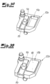
- Fig. 3a, 3b show an example of the lower receiving element 12a of the first fastening part, from which on the one hand the groove 15 with the guide carriage 16 and on the other hand the receiving formation in the form of the recess 17a is shown in more detail.
- the recess serves to accommodate a fire protection element 18, which is formed from a material that foams under the influence of heat and is preferably flush with a surface 19 adjacent to the receiving space 13a.
- All recesses 17a, 17b are designed in such a way that they are open relative to the receiving spaces 13a, 13b, so that in the event of a fire, the fire protection element 18 can foam up, enter the recesses 17a, 17b into the receiving spaces 13a, 13b and fill them.
- Articulated brackets 9, 10 can be held for as long as possible, so that in interaction with the fire protection strip 5, on the one hand, sufficient sealing is ensured and, on the other hand, the door leaf 1 can be held within the door frame 2 for a long period of time.
- both the fire protection strip 5 and the fire protection element 18 are made of a material that begins to foam at a temperature of approximately 130 ° C, so that the desired effect can occur at an early stage.
Landscapes
- Engineering & Computer Science (AREA)
- Mechanical Engineering (AREA)
- Special Wing (AREA)
Claims (15)
- Paumelle (3), pourvue d'une première et d'une deuxième pièces de fixation (6, 7) et pourvue d'au moins un étrier articulé (9, 10), qui relie l'une à l'autre les pièces de fixation de manière mobile en pivotement, au moins l'une des pièces de fixation (6, 7) comportant un élément de logement (11a, 11b, 12a, 12b) supérieur et inférieur constituant un espace de logement (13a, 13b), sur lesquels l'au moins un étrier articulé (9, 10) est logé de manière mobile en rotation,
caractérisé
en ce qu'au moins l'un des éléments de logement (11a, 11b, 12a, 12b) comporte une empreinte de logement ouverte en direction de l'espace de logement (13a, 13b), dans laquelle est placé un élément pare-feu (18), constitué en une matière moussant sous l'effet de la chaleur. - Paumelle (3) selon la revendication 1, caractérisée en ce que l'empreinte de logement est conçue sous la forme d'un creux (17a, 17b).
- Paumelle (3) selon la revendication 2, caractérisée en ce que dans un état non moussé, l'élément pare-feu (18) est adjacent à fleur d'une surface (19) de l'élément de logement (11a, 11b, 12a, 12b) qui est adjacent au creux (17a, 17b).
- Paumelle (3) selon l'une quelconque des revendications 1 à 3, caractérisée en ce que dans l'élément de logement (11a, 11b, 12a, 12b) supérieur et inférieur, il est prévu chaque fois une empreinte de logement et un élément pare-feu (18) placé sans l'empreinte de logement.
- Paumelle (3) selon l'une quelconque des revendications 1 à 4, caractérisée en ce que l'élément pare-feu (18) placé dans l'empreinte de logement mousse à une température supérieure à 130 °C, de préférence supérieure à 150 °C.
- Paumelle (3) selon l'une quelconque des revendications 1 à 5, caractérisée en ce que les pièces de fixation (6, 7) sont constituées au moins partiellement en un zinc moulé sous pression.
- Paumelle (3) selon l'une quelconque des revendications 1 à 6, caractérisée en ce que les pièces de fixation (6, 7) sont insérables dans des évidements (8) dans le côté étroit d'un vantail (1) et dans le côté intrados d'un chambranle (2).
- Paumelle (3) selon l'une quelconque des revendications 1 à 7, caractérisée en ce que sont prévus au moins un premier et un deuxième étriers articulés (9, 10), qui sont reliés l'un à l'autre de manière mobile en rotation autour d'un axe de rotation (D) vertical.
- Paumelle (3) selon la revendication 8, caractérisée en ce que le premier étrier articulé (9) est logé en étant déplaçable dans l'élément de logement (11a, 12a) supérieur et inférieur de la première pièce de fixation (6).
- Paumelle (3) selon l'une quelconque des revendications 1 à 9, caractérisée en ce que les éléments de logement (11a, 11b, 12a, 12b) sont placés de manière au moins partiellement amovible sur un corps de base (14a, 14b) des pièces de fixation (6, 7).
- Paumelle (3) selon l'une quelconque des revendications 1 à 10, caractérisée en ce que dans une position de fermeture, l'étrier articulé (9, 10) est placé sensiblement dans des espaces de logement (13a, 13b) des pièces de fixation (6, 7).
- Porte, pourvue d'un vantail (1), d'un chambranle (2) et d'au moins une paumelle (3) selon l'une quelconque des revendications 1 à 11, par l'intermédiaire de laquelle le vantail (2) est fixé de manière mobile en pivotement au chambranle (1), la première pièce de fixation (6) étant insérée dans un évidement (8) dans un côté étroit du vantail (1) et la deuxième pièce de fixation (7) étant placée dans un évidement (8) dans un côté intrados du chambranle (2).
- Porte selon la revendication 12, caractérisée en ce que le chambranle (2) comporte une feuillure (4) à laquelle le vantail (1) est adjacent dans une position de fermeture et sur un côté de la feuillure (4) qui fait face au vantail (1) étant placée une bande pare-feu (5) s'écoulant dans une direction verticale (Z) en une matière moussant sous l'effet de la chaleur.
- Porte selon la revendication 12 ou 13, caractérisée en ce que le vantail (1) et / ou le chambranle (2) sont constitués au moins partiellement en bois.
- Porte selon l'une quelconque des revendications 12 à 14, caractérisée en ce qu'au moins deux paumelles (3) de constitution identique sont placées en superposition dans la direction verticale (Z).
Applications Claiming Priority (1)
| Application Number | Priority Date | Filing Date | Title |
|---|---|---|---|
| DE102021129869.5A DE102021129869B3 (de) | 2021-11-16 | 2021-11-16 | Türband mit Brandschutzelement |
Publications (3)
| Publication Number | Publication Date |
|---|---|
| EP4180602A1 EP4180602A1 (fr) | 2023-05-17 |
| EP4180602B1 true EP4180602B1 (fr) | 2024-02-28 |
| EP4180602C0 EP4180602C0 (fr) | 2024-02-28 |
Family
ID=83546724
Family Applications (1)
| Application Number | Title | Priority Date | Filing Date |
|---|---|---|---|
| EP22199232.4A Active EP4180602B1 (fr) | 2021-11-16 | 2022-09-30 | Penture dotée d'un élément de protection contre l'incendie |
Country Status (5)
| Country | Link |
|---|---|
| US (1) | US12054976B2 (fr) |
| EP (1) | EP4180602B1 (fr) |
| DE (1) | DE102021129869B3 (fr) |
| ES (1) | ES2985023T3 (fr) |
| PL (1) | PL4180602T3 (fr) |
Families Citing this family (2)
| Publication number | Priority date | Publication date | Assignee | Title |
|---|---|---|---|---|
| PL4185759T3 (pl) * | 2020-09-22 | 2024-09-16 | Sfs Intec Ag | Ukryty zawias do zlicowanych lub przylgowych drzwi lub okien |
| DE102021129910B3 (de) * | 2021-11-16 | 2023-01-26 | Simonswerk Gmbh | Türband |
Family Cites Families (17)
| Publication number | Priority date | Publication date | Assignee | Title |
|---|---|---|---|---|
| US3001224A (en) * | 1960-05-16 | 1961-09-26 | Charles J Soss | Concealed hinge |
| US3566541A (en) * | 1969-03-06 | 1971-03-02 | Rixson Inc | Protective barrier for products of combustion |
| GB1580160A (en) * | 1978-04-27 | 1980-11-26 | Dixon International Ltd | Fire-resistant seals |
| GB2186794B (en) * | 1986-02-20 | 1990-05-02 | Laidlaw Thomson Group Plc | Ironmongery |
| GB2245025B (en) | 1990-05-16 | 1993-11-24 | Jebron Ltd | Hinge |
| GB2275491B (en) | 1993-02-24 | 1996-04-03 | Tools Ltd Nv | Fire door |
| US5492208A (en) * | 1994-02-01 | 1996-02-20 | Pemko Manufacturing Company | Intumescent security pin for fire rated doors |
| US5685045A (en) * | 1996-03-26 | 1997-11-11 | Select Products Limited | Intumescent material in a continuous pinless hinge |
| US6170210B1 (en) * | 1999-03-16 | 2001-01-09 | C. Hager & Sons Hinge Manufacturing Company | Continuous gear hinge with intumescent seals |
| DE202005008633U1 (de) * | 2005-05-31 | 2006-10-19 | Dr. Hahn Gmbh & Co. Kg | Bandsystem |
| GB2451276B (en) * | 2007-07-26 | 2012-04-18 | Phil Barsby | Double swing (180°) continuous hinge |
| DE102011050413B3 (de) * | 2011-05-17 | 2012-04-12 | Simonswerk, Gesellschaft mit beschränkter Haftung | Türband für eine verdeckte Anordnung zwischen Türflügel und Türzarge |
| DE202014102793U1 (de) | 2014-06-17 | 2014-06-27 | Simonswerk, Gesellschaft mit beschränkter Haftung | Türblattseitiges Bandteil eines Türbandes und Anordnung hiermit |
| DE102015112647B3 (de) * | 2015-07-31 | 2016-01-21 | Simonswerk, Gesellschaft mit beschränkter Haftung | Türband für eine verdeckte Anordnung zwischen Türflügel und Türzarge |
| DE102015116192B3 (de) * | 2015-09-24 | 2016-04-14 | Simonswerk, Gesellschaft mit beschränkter Haftung | Bandaufnahmeteil für ein verdeckt liegendes Bandsystem für Türen oder Fenster und Türband mit dem Bandaufnahmeteil |
| ITUB20156253A1 (it) * | 2015-12-04 | 2017-06-04 | Dierre Spa | Cerniera a scomparsa |
| JP6978297B2 (ja) * | 2017-12-15 | 2021-12-08 | Ykk Ap株式会社 | 建具 |
-
2021
- 2021-11-16 DE DE102021129869.5A patent/DE102021129869B3/de active Active
-
2022
- 2022-09-30 PL PL22199232.4T patent/PL4180602T3/pl unknown
- 2022-09-30 ES ES22199232T patent/ES2985023T3/es active Active
- 2022-09-30 EP EP22199232.4A patent/EP4180602B1/fr active Active
- 2022-10-21 US US17/971,192 patent/US12054976B2/en active Active
Also Published As
| Publication number | Publication date |
|---|---|
| EP4180602A1 (fr) | 2023-05-17 |
| US20230151658A1 (en) | 2023-05-18 |
| ES2985023T3 (es) | 2024-11-04 |
| PL4180602T3 (pl) | 2024-05-27 |
| US12054976B2 (en) | 2024-08-06 |
| DE102021129869B3 (de) | 2023-02-16 |
| EP4180602C0 (fr) | 2024-02-28 |
Similar Documents
| Publication | Publication Date | Title |
|---|---|---|
| EP3346078B1 (fr) | Porte de chambre | |
| EP4180602B1 (fr) | Penture dotée d'un élément de protection contre l'incendie | |
| DE212015000262U1 (de) | Mit Fliegengitter versehene(s), nach innen öffnende(s) Tür bzw. Fenster mit nach außen öffnendem Glasflügel und Drückergarnitur sowie Scharnier dafür | |
| DE202014102793U1 (de) | Türblattseitiges Bandteil eines Türbandes und Anordnung hiermit | |
| EP2754841B1 (fr) | Vitrage coupe-feu avec porte en bois | |
| EP2601369B1 (fr) | Porte coupe-feu pour véhicules sur rails | |
| AT521183B1 (de) | Wandöffnung mit daran angebrachter Zarge und schwenkbarem Flügel und Scharnier | |
| DE4318209C2 (de) | Türanschlagprofil für Schwenktüren | |
| DE19719113C2 (de) | Türsystem | |
| DE3001070A1 (de) | Eckgelenk fuer drehkippfenster, -tueren o.dgl. | |
| CH708369A2 (de) | Brandschutz-Schiebetür. | |
| DE2947509A1 (de) | Tuer mit einem seitlich und oben ueberfaelzten und unten stumpfen tuerblatt | |
| DE2022912C3 (de) | Zweiflügelige Feuerschutztür | |
| DE3990925C2 (de) | Verfahren zum Anbringen einer entfernbaren Zusatzscheibe bei der Herstellung/Renovierung von Fenstern | |
| EP3461982B1 (fr) | Système de porte | |
| DE4212902C1 (en) | Window and frame with transom - has transom window suspended by linkage from frame members and forming stop for hinging leaves | |
| DE202018006686U1 (de) | Brandabschluss | |
| DE2519666A1 (de) | Feuerschutztuer | |
| WO1984000395A1 (fr) | Element de separation, notamment panneau de porte accordeon en caisson autoportant | |
| DE202022107195U1 (de) | Türzarge | |
| DE8905142U1 (de) | Gebäudeaußentür | |
| EP4534792A1 (fr) | Porte avec segments de porte mobiles | |
| DE102005013978B3 (de) | Tür | |
| DE202007007569U1 (de) | Tor, insbesondere Feuerschutz-Schiebetor, mit Fluchttür und Dichtungsanordnung | |
| AT336864B (de) | Fenster, insbesondere fur die montage in einem schragen dach |
Legal Events
| Date | Code | Title | Description |
|---|---|---|---|
| PUAI | Public reference made under article 153(3) epc to a published international application that has entered the european phase |
Free format text: ORIGINAL CODE: 0009012 |
|
| STAA | Information on the status of an ep patent application or granted ep patent |
Free format text: STATUS: THE APPLICATION HAS BEEN PUBLISHED |
|
| AK | Designated contracting states |
Kind code of ref document: A1 Designated state(s): AL AT BE BG CH CY CZ DE DK EE ES FI FR GB GR HR HU IE IS IT LI LT LU LV MC MK MT NL NO PL PT RO RS SE SI SK SM TR |
|
| STAA | Information on the status of an ep patent application or granted ep patent |
Free format text: STATUS: REQUEST FOR EXAMINATION WAS MADE |
|
| 17P | Request for examination filed |
Effective date: 20230523 |
|
| RBV | Designated contracting states (corrected) |
Designated state(s): AL AT BE BG CH CY CZ DE DK EE ES FI FR GB GR HR HU IE IS IT LI LT LU LV MC MK MT NL NO PL PT RO RS SE SI SK SM TR |
|
| GRAP | Despatch of communication of intention to grant a patent |
Free format text: ORIGINAL CODE: EPIDOSNIGR1 |
|
| STAA | Information on the status of an ep patent application or granted ep patent |
Free format text: STATUS: GRANT OF PATENT IS INTENDED |
|
| RIC1 | Information provided on ipc code assigned before grant |
Ipc: E05D 3/06 20060101ALI20230823BHEP Ipc: E05D 5/02 20060101AFI20230823BHEP |
|
| INTG | Intention to grant announced |
Effective date: 20230927 |
|
| GRAS | Grant fee paid |
Free format text: ORIGINAL CODE: EPIDOSNIGR3 |
|
| GRAA | (expected) grant |
Free format text: ORIGINAL CODE: 0009210 |
|
| STAA | Information on the status of an ep patent application or granted ep patent |
Free format text: STATUS: THE PATENT HAS BEEN GRANTED |
|
| AK | Designated contracting states |
Kind code of ref document: B1 Designated state(s): AL AT BE BG CH CY CZ DE DK EE ES FI FR GB GR HR HU IE IS IT LI LT LU LV MC MK MT NL NO PL PT RO RS SE SI SK SM TR |
|
| REG | Reference to a national code |
Ref country code: GB Ref legal event code: FG4D Free format text: NOT ENGLISH |
|
| REG | Reference to a national code |
Ref country code: CH Ref legal event code: EP |
|
| REG | Reference to a national code |
Ref country code: DE Ref legal event code: R096 Ref document number: 502022000563 Country of ref document: DE |
|
| REG | Reference to a national code |
Ref country code: IE Ref legal event code: FG4D Free format text: LANGUAGE OF EP DOCUMENT: GERMAN |
|
| U01 | Request for unitary effect filed |
Effective date: 20240319 |
|
| U07 | Unitary effect registered |
Designated state(s): AT BE BG DE DK EE FI FR IT LT LU LV MT NL PT SE SI Effective date: 20240326 |
|
| PG25 | Lapsed in a contracting state [announced via postgrant information from national office to epo] |
Ref country code: IS Free format text: LAPSE BECAUSE OF FAILURE TO SUBMIT A TRANSLATION OF THE DESCRIPTION OR TO PAY THE FEE WITHIN THE PRESCRIBED TIME-LIMIT Effective date: 20240628 |
|
| PG25 | Lapsed in a contracting state [announced via postgrant information from national office to epo] |
Ref country code: GR Free format text: LAPSE BECAUSE OF FAILURE TO SUBMIT A TRANSLATION OF THE DESCRIPTION OR TO PAY THE FEE WITHIN THE PRESCRIBED TIME-LIMIT Effective date: 20240529 |
|
| PG25 | Lapsed in a contracting state [announced via postgrant information from national office to epo] |
Ref country code: HR Free format text: LAPSE BECAUSE OF FAILURE TO SUBMIT A TRANSLATION OF THE DESCRIPTION OR TO PAY THE FEE WITHIN THE PRESCRIBED TIME-LIMIT Effective date: 20240228 Ref country code: RS Free format text: LAPSE BECAUSE OF FAILURE TO SUBMIT A TRANSLATION OF THE DESCRIPTION OR TO PAY THE FEE WITHIN THE PRESCRIBED TIME-LIMIT Effective date: 20240528 |
|
| PG25 | Lapsed in a contracting state [announced via postgrant information from national office to epo] |
Ref country code: RS Free format text: LAPSE BECAUSE OF FAILURE TO SUBMIT A TRANSLATION OF THE DESCRIPTION OR TO PAY THE FEE WITHIN THE PRESCRIBED TIME-LIMIT Effective date: 20240528 Ref country code: NO Free format text: LAPSE BECAUSE OF FAILURE TO SUBMIT A TRANSLATION OF THE DESCRIPTION OR TO PAY THE FEE WITHIN THE PRESCRIBED TIME-LIMIT Effective date: 20240528 Ref country code: IS Free format text: LAPSE BECAUSE OF FAILURE TO SUBMIT A TRANSLATION OF THE DESCRIPTION OR TO PAY THE FEE WITHIN THE PRESCRIBED TIME-LIMIT Effective date: 20240628 Ref country code: HR Free format text: LAPSE BECAUSE OF FAILURE TO SUBMIT A TRANSLATION OF THE DESCRIPTION OR TO PAY THE FEE WITHIN THE PRESCRIBED TIME-LIMIT Effective date: 20240228 Ref country code: GR Free format text: LAPSE BECAUSE OF FAILURE TO SUBMIT A TRANSLATION OF THE DESCRIPTION OR TO PAY THE FEE WITHIN THE PRESCRIBED TIME-LIMIT Effective date: 20240529 |
|
| U20 | Renewal fee for the european patent with unitary effect paid |
Year of fee payment: 3 Effective date: 20240830 |
|
| PG25 | Lapsed in a contracting state [announced via postgrant information from national office to epo] |
Ref country code: SM Free format text: LAPSE BECAUSE OF FAILURE TO SUBMIT A TRANSLATION OF THE DESCRIPTION OR TO PAY THE FEE WITHIN THE PRESCRIBED TIME-LIMIT Effective date: 20240228 |
|
| PG25 | Lapsed in a contracting state [announced via postgrant information from national office to epo] |
Ref country code: SK Free format text: LAPSE BECAUSE OF FAILURE TO SUBMIT A TRANSLATION OF THE DESCRIPTION OR TO PAY THE FEE WITHIN THE PRESCRIBED TIME-LIMIT Effective date: 20240228 |
|
| PG25 | Lapsed in a contracting state [announced via postgrant information from national office to epo] |
Ref country code: SM Free format text: LAPSE BECAUSE OF FAILURE TO SUBMIT A TRANSLATION OF THE DESCRIPTION OR TO PAY THE FEE WITHIN THE PRESCRIBED TIME-LIMIT Effective date: 20240228 Ref country code: SK Free format text: LAPSE BECAUSE OF FAILURE TO SUBMIT A TRANSLATION OF THE DESCRIPTION OR TO PAY THE FEE WITHIN THE PRESCRIBED TIME-LIMIT Effective date: 20240228 Ref country code: RO Free format text: LAPSE BECAUSE OF FAILURE TO SUBMIT A TRANSLATION OF THE DESCRIPTION OR TO PAY THE FEE WITHIN THE PRESCRIBED TIME-LIMIT Effective date: 20240228 |
|
| REG | Reference to a national code |
Ref country code: ES Ref legal event code: FG2A Ref document number: 2985023 Country of ref document: ES Kind code of ref document: T3 Effective date: 20241104 |
|
| REG | Reference to a national code |
Ref country code: DE Ref legal event code: R097 Ref document number: 502022000563 Country of ref document: DE |
|
| PLBE | No opposition filed within time limit |
Free format text: ORIGINAL CODE: 0009261 |
|
| STAA | Information on the status of an ep patent application or granted ep patent |
Free format text: STATUS: NO OPPOSITION FILED WITHIN TIME LIMIT |
|
| 26N | No opposition filed |
Effective date: 20241129 |
|
| PG25 | Lapsed in a contracting state [announced via postgrant information from national office to epo] |
Ref country code: MC Free format text: LAPSE BECAUSE OF FAILURE TO SUBMIT A TRANSLATION OF THE DESCRIPTION OR TO PAY THE FEE WITHIN THE PRESCRIBED TIME-LIMIT Effective date: 20240228 |
|
| PG25 | Lapsed in a contracting state [announced via postgrant information from national office to epo] |
Ref country code: IE Free format text: LAPSE BECAUSE OF NON-PAYMENT OF DUE FEES Effective date: 20240930 |
|
| REG | Reference to a national code |
Ref country code: CH Ref legal event code: U11 Free format text: ST27 STATUS EVENT CODE: U-0-0-U10-U11 (AS PROVIDED BY THE NATIONAL OFFICE) Effective date: 20251001 |
|
| PGFP | Annual fee paid to national office [announced via postgrant information from national office to epo] |
Ref country code: PL Payment date: 20250918 Year of fee payment: 4 |
|
| PGFP | Annual fee paid to national office [announced via postgrant information from national office to epo] |
Ref country code: CZ Payment date: 20250925 Year of fee payment: 4 |
|
| U20 | Renewal fee for the european patent with unitary effect paid |
Year of fee payment: 4 Effective date: 20250917 |
|
| PGFP | Annual fee paid to national office [announced via postgrant information from national office to epo] |
Ref country code: CH Payment date: 20251001 Year of fee payment: 4 |
|
| PG25 | Lapsed in a contracting state [announced via postgrant information from national office to epo] |
Ref country code: CY Free format text: LAPSE BECAUSE OF FAILURE TO SUBMIT A TRANSLATION OF THE DESCRIPTION OR TO PAY THE FEE WITHIN THE PRESCRIBED TIME-LIMIT; INVALID AB INITIO Effective date: 20220930 |
|
| PGFP | Annual fee paid to national office [announced via postgrant information from national office to epo] |
Ref country code: ES Payment date: 20251030 Year of fee payment: 4 |
|
| PG25 | Lapsed in a contracting state [announced via postgrant information from national office to epo] |
Ref country code: HU Free format text: LAPSE BECAUSE OF FAILURE TO SUBMIT A TRANSLATION OF THE DESCRIPTION OR TO PAY THE FEE WITHIN THE PRESCRIBED TIME-LIMIT; INVALID AB INITIO Effective date: 20220930 |