EP4180710A1 - Beleuchtungsvorrichtung für kraftfahrzeugscheinwerfer - Google Patents
Beleuchtungsvorrichtung für kraftfahrzeugscheinwerfer Download PDFInfo
- Publication number
- EP4180710A1 EP4180710A1 EP21207916.4A EP21207916A EP4180710A1 EP 4180710 A1 EP4180710 A1 EP 4180710A1 EP 21207916 A EP21207916 A EP 21207916A EP 4180710 A1 EP4180710 A1 EP 4180710A1
- Authority
- EP
- European Patent Office
- Prior art keywords
- light
- illumination device
- rays
- optic body
- section
- Prior art date
- Legal status (The legal status is an assumption and is not a legal conclusion. Google has not performed a legal analysis and makes no representation as to the accuracy of the status listed.)
- Granted
Links
Images


Classifications
-
- F—MECHANICAL ENGINEERING; LIGHTING; HEATING; WEAPONS; BLASTING
- F21—LIGHTING
- F21S—NON-PORTABLE LIGHTING DEVICES; SYSTEMS THEREOF; VEHICLE LIGHTING DEVICES SPECIALLY ADAPTED FOR VEHICLE EXTERIORS
- F21S41/00—Illuminating devices specially adapted for vehicle exteriors, e.g. headlamps
- F21S41/10—Illuminating devices specially adapted for vehicle exteriors, e.g. headlamps characterised by the light source
- F21S41/14—Illuminating devices specially adapted for vehicle exteriors, e.g. headlamps characterised by the light source characterised by the type of light source
- F21S41/141—Light emitting diodes [LED]
-
- F—MECHANICAL ENGINEERING; LIGHTING; HEATING; WEAPONS; BLASTING
- F21—LIGHTING
- F21S—NON-PORTABLE LIGHTING DEVICES; SYSTEMS THEREOF; VEHICLE LIGHTING DEVICES SPECIALLY ADAPTED FOR VEHICLE EXTERIORS
- F21S41/00—Illuminating devices specially adapted for vehicle exteriors, e.g. headlamps
- F21S41/20—Illuminating devices specially adapted for vehicle exteriors, e.g. headlamps characterised by refractors, transparent cover plates, light guides or filters
- F21S41/25—Projection lenses
- F21S41/255—Lenses with a front view of circular or truncated circular outline
-
- F—MECHANICAL ENGINEERING; LIGHTING; HEATING; WEAPONS; BLASTING
- F21—LIGHTING
- F21S—NON-PORTABLE LIGHTING DEVICES; SYSTEMS THEREOF; VEHICLE LIGHTING DEVICES SPECIALLY ADAPTED FOR VEHICLE EXTERIORS
- F21S41/00—Illuminating devices specially adapted for vehicle exteriors, e.g. headlamps
- F21S41/10—Illuminating devices specially adapted for vehicle exteriors, e.g. headlamps characterised by the light source
- F21S41/14—Illuminating devices specially adapted for vehicle exteriors, e.g. headlamps characterised by the light source characterised by the type of light source
- F21S41/141—Light emitting diodes [LED]
- F21S41/147—Light emitting diodes [LED] the main emission direction of the LED being angled to the optical axis of the illuminating device
-
- F—MECHANICAL ENGINEERING; LIGHTING; HEATING; WEAPONS; BLASTING
- F21—LIGHTING
- F21S—NON-PORTABLE LIGHTING DEVICES; SYSTEMS THEREOF; VEHICLE LIGHTING DEVICES SPECIALLY ADAPTED FOR VEHICLE EXTERIORS
- F21S41/00—Illuminating devices specially adapted for vehicle exteriors, e.g. headlamps
- F21S41/10—Illuminating devices specially adapted for vehicle exteriors, e.g. headlamps characterised by the light source
- F21S41/14—Illuminating devices specially adapted for vehicle exteriors, e.g. headlamps characterised by the light source characterised by the type of light source
- F21S41/141—Light emitting diodes [LED]
- F21S41/151—Light emitting diodes [LED] arranged in one or more lines
-
- F—MECHANICAL ENGINEERING; LIGHTING; HEATING; WEAPONS; BLASTING
- F21—LIGHTING
- F21S—NON-PORTABLE LIGHTING DEVICES; SYSTEMS THEREOF; VEHICLE LIGHTING DEVICES SPECIALLY ADAPTED FOR VEHICLE EXTERIORS
- F21S41/00—Illuminating devices specially adapted for vehicle exteriors, e.g. headlamps
- F21S41/20—Illuminating devices specially adapted for vehicle exteriors, e.g. headlamps characterised by refractors, transparent cover plates, light guides or filters
- F21S41/24—Light guides
-
- F—MECHANICAL ENGINEERING; LIGHTING; HEATING; WEAPONS; BLASTING
- F21—LIGHTING
- F21S—NON-PORTABLE LIGHTING DEVICES; SYSTEMS THEREOF; VEHICLE LIGHTING DEVICES SPECIALLY ADAPTED FOR VEHICLE EXTERIORS
- F21S41/00—Illuminating devices specially adapted for vehicle exteriors, e.g. headlamps
- F21S41/20—Illuminating devices specially adapted for vehicle exteriors, e.g. headlamps characterised by refractors, transparent cover plates, light guides or filters
- F21S41/25—Projection lenses
-
- F—MECHANICAL ENGINEERING; LIGHTING; HEATING; WEAPONS; BLASTING
- F21—LIGHTING
- F21S—NON-PORTABLE LIGHTING DEVICES; SYSTEMS THEREOF; VEHICLE LIGHTING DEVICES SPECIALLY ADAPTED FOR VEHICLE EXTERIORS
- F21S41/00—Illuminating devices specially adapted for vehicle exteriors, e.g. headlamps
- F21S41/20—Illuminating devices specially adapted for vehicle exteriors, e.g. headlamps characterised by refractors, transparent cover plates, light guides or filters
- F21S41/25—Projection lenses
- F21S41/265—Composite lenses; Lenses with a patch-like shape
-
- F—MECHANICAL ENGINEERING; LIGHTING; HEATING; WEAPONS; BLASTING
- F21—LIGHTING
- F21S—NON-PORTABLE LIGHTING DEVICES; SYSTEMS THEREOF; VEHICLE LIGHTING DEVICES SPECIALLY ADAPTED FOR VEHICLE EXTERIORS
- F21S41/00—Illuminating devices specially adapted for vehicle exteriors, e.g. headlamps
- F21S41/20—Illuminating devices specially adapted for vehicle exteriors, e.g. headlamps characterised by refractors, transparent cover plates, light guides or filters
- F21S41/25—Projection lenses
- F21S41/275—Lens surfaces, e.g. coatings or surface structures
-
- F—MECHANICAL ENGINEERING; LIGHTING; HEATING; WEAPONS; BLASTING
- F21—LIGHTING
- F21S—NON-PORTABLE LIGHTING DEVICES; SYSTEMS THEREOF; VEHICLE LIGHTING DEVICES SPECIALLY ADAPTED FOR VEHICLE EXTERIORS
- F21S41/00—Illuminating devices specially adapted for vehicle exteriors, e.g. headlamps
- F21S41/20—Illuminating devices specially adapted for vehicle exteriors, e.g. headlamps characterised by refractors, transparent cover plates, light guides or filters
- F21S41/285—Refractors, transparent cover plates, light guides or filters not provided in groups F21S41/24 - F21S41/2805
-
- F—MECHANICAL ENGINEERING; LIGHTING; HEATING; WEAPONS; BLASTING
- F21—LIGHTING
- F21V—FUNCTIONAL FEATURES OR DETAILS OF LIGHTING DEVICES OR SYSTEMS THEREOF; STRUCTURAL COMBINATIONS OF LIGHTING DEVICES WITH OTHER ARTICLES, NOT OTHERWISE PROVIDED FOR
- F21V5/00—Refractors for light sources
- F21V5/04—Refractors for light sources of lens shape
-
- F—MECHANICAL ENGINEERING; LIGHTING; HEATING; WEAPONS; BLASTING
- F21—LIGHTING
- F21V—FUNCTIONAL FEATURES OR DETAILS OF LIGHTING DEVICES OR SYSTEMS THEREOF; STRUCTURAL COMBINATIONS OF LIGHTING DEVICES WITH OTHER ARTICLES, NOT OTHERWISE PROVIDED FOR
- F21V5/00—Refractors for light sources
- F21V5/08—Refractors for light sources producing an asymmetric light distribution
-
- F—MECHANICAL ENGINEERING; LIGHTING; HEATING; WEAPONS; BLASTING
- F21—LIGHTING
- F21S—NON-PORTABLE LIGHTING DEVICES; SYSTEMS THEREOF; VEHICLE LIGHTING DEVICES SPECIALLY ADAPTED FOR VEHICLE EXTERIORS
- F21S41/00—Illuminating devices specially adapted for vehicle exteriors, e.g. headlamps
- F21S41/30—Illuminating devices specially adapted for vehicle exteriors, e.g. headlamps characterised by reflectors
- F21S41/32—Optical layout thereof
- F21S41/322—Optical layout thereof the reflector using total internal reflection
-
- F—MECHANICAL ENGINEERING; LIGHTING; HEATING; WEAPONS; BLASTING
- F21—LIGHTING
- F21V—FUNCTIONAL FEATURES OR DETAILS OF LIGHTING DEVICES OR SYSTEMS THEREOF; STRUCTURAL COMBINATIONS OF LIGHTING DEVICES WITH OTHER ARTICLES, NOT OTHERWISE PROVIDED FOR
- F21V2200/00—Use of light guides, e.g. fibre optic devices, in lighting devices or systems
-
- F—MECHANICAL ENGINEERING; LIGHTING; HEATING; WEAPONS; BLASTING
- F21—LIGHTING
- F21W—INDEXING SCHEME ASSOCIATED WITH SUBCLASSES F21K, F21L, F21S and F21V, RELATING TO USES OR APPLICATIONS OF LIGHTING DEVICES OR SYSTEMS
- F21W2102/00—Exterior vehicle lighting devices for illuminating purposes
- F21W2102/10—Arrangement or contour of the emitted light
- F21W2102/13—Arrangement or contour of the emitted light for high-beam region or low-beam region
-
- F—MECHANICAL ENGINEERING; LIGHTING; HEATING; WEAPONS; BLASTING
- F21—LIGHTING
- F21W—INDEXING SCHEME ASSOCIATED WITH SUBCLASSES F21K, F21L, F21S and F21V, RELATING TO USES OR APPLICATIONS OF LIGHTING DEVICES OR SYSTEMS
- F21W2102/00—Exterior vehicle lighting devices for illuminating purposes
- F21W2102/10—Arrangement or contour of the emitted light
- F21W2102/13—Arrangement or contour of the emitted light for high-beam region or low-beam region
- F21W2102/135—Arrangement or contour of the emitted light for high-beam region or low-beam region the light having cut-off lines, i.e. clear borderlines between emitted regions and dark regions
-
- F—MECHANICAL ENGINEERING; LIGHTING; HEATING; WEAPONS; BLASTING
- F21—LIGHTING
- F21W—INDEXING SCHEME ASSOCIATED WITH SUBCLASSES F21K, F21L, F21S and F21V, RELATING TO USES OR APPLICATIONS OF LIGHTING DEVICES OR SYSTEMS
- F21W2102/00—Exterior vehicle lighting devices for illuminating purposes
- F21W2102/10—Arrangement or contour of the emitted light
- F21W2102/13—Arrangement or contour of the emitted light for high-beam region or low-beam region
- F21W2102/135—Arrangement or contour of the emitted light for high-beam region or low-beam region the light having cut-off lines, i.e. clear borderlines between emitted regions and dark regions
- F21W2102/155—Arrangement or contour of the emitted light for high-beam region or low-beam region the light having cut-off lines, i.e. clear borderlines between emitted regions and dark regions having inclined and horizontal cutoff lines
Definitions
- the invention relates to an illumination device for a motor vehicle headlamp for generating a low beam light distribution, wherein a vertical extension of the low beam light distribution extends along a V-V-line from at least 0° down to at least -10° on the V-V-line, said illumination device comprises:
- the invention relates to a motor vehicle headlamp comprising at least one illumination device according to the invention.
- the construction of the corresponding illumination device demands certain requirements that results sometimes in not fulfilling legal requirements on a low beam light distribution (see for example in Official Journal of the EU L 250/92 - 22.08.2014 ).
- an enhanced illumination device is required.
- the at least one light collecting element in combination with the optic body allow at least three sets of light-ray paths
- the illumination device comprises at least two light sources, wherein the common light input section comprises at least two light collecting elements each assigned to one light source.
- the light sources are arranged in at least one row along a straight horizontal line, wherein the corresponding light collecting elements are arranged in rows along a straight horizontal line, wherein the straight horizontal lines are substantially orthogonal to the main direction.
- the at least one light source is built as a LED.
- the at least one light collecting element is built as TIR-lens.
- the light exit surface and the shell surface intersect in a common surface section line, said common surface section line builds an asymmetric cut-off boundary for the low beam light distribution.
- the projection lens system comprises an optical axis and the light exit surface having a surface vector, which surface vector is inclined to the optical axis of the projection lens system.
- the projection lens system comprises a curved focal surface, preferably a Petzval-surface, wherein the light exit surface is inclined to the curved focal surface, so that only the common surface section line is arranged in the curved focal surface.
- the surface vector of the light exit surface is - seen in a correctly installed state of the illumination device in a vehicle - inclined upward.
- the at least one light collecting element having a curved light input surface for coupling light-rays from the assigned light source into the optic body, wherein the curved light input surface comprises a central section having a convex form.
- the curved light input surface of the at least one light collecting element comprises a first deflection section corresponding to the second deflection surface, wherein the deflection section is configured to deflect light-rays incident on the first deflection section to the second deflection surface.
- the first deflection section has a curvature opposite to the curvature of the central section of the light input surface, preferably a concave curvature.
- the at least one light collecting element comprises a second deflection section corresponding to the first deflection surface, wherein the second deflection section is configured to deflect light-rays incident on second the deflection section to the first deflection surface, wherein light rays following a fourth light ray path, when incident on the second deflection section, and wherein the fourth light ray path contributes to the low beam light distribution.
- the at least one light source emits light-rays in a light emitting direction, wherein the at least one light source is arranged in a way, that the light emit direction is not parallel to the main direction of the illumination device.
- light emitting direction is to be understood as a direction, in which the at least one light source emits the most or the strongest light as a result of its directionality - or in other words, where the highest light flux is present.
- the object of the invention is also solved by a motor vehicle headlamp comprising at least one illumination device according to the invention.
- the object can also be achieved by a motor vehicle headlamp comprising at least one illumination device according to the invention.
- Fig. 1 shows an example of an illumination device 10 for a motor vehicle headlamp for generating a low beam light distribution LB , wherein a vertical extension of the low beam light distribution extends along a V-V-line from at least 0° down to at least -10° on the V-V-line, which can be seen in more detail in Fig. 4 .
- the illumination device 10 comprises light sources 50 configured to emit light-rays, an optic body 100 comprising a common light input section 110 for coupling light-rays from the light sources 50 into the optic body 100 , wherein the light sources are built as LEDs.
- the common light input section 110 having light collecting elements 120 , each of which is assigned to a respective light source 50 and is configured to couple light-rays from the assigned light source 50 into the optic body 100 .
- the optic body 100 comprises a light output section 130 for decoupling light-rays that are coupled into the optic body 100 via the common light input section 110 , out of the optic body 100 in a main direction X of the illumination device 10 .
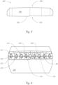
- the light sources 50 are arranged only in a row along a straight horizontal line, wherein the corresponding light collecting elements 120 are arranged only in a row along a straight horizontal line, wherein the straight horizontal lines are substantially orthogonal to the main direction X , which can be seen for example in Fig. 6 , which shows a back view of the optic body 100 .
- the optic body 100 also comprises a shell surface 140 limiting the optic body 100 by extending between the common light input section 110 and the light output section 130 , said shell surface 140 is configured to deflect light-rays coupled into the optic body 100 , preferably by total inner reflection.
- the illumination device 10 comprises further a projection lens system 200 , comprising at least one lens (in the shown example exactly one lens), arranged downstream of the optic body 100 along the main direction X in order to receive light-rays emitted from the light output section 130 of the optic body 100 , wherein the projection lens system 200 is configured to project the light-rays in front of the illumination device 10 , wherein the projection lens system 200 in combination with the light sources 50 and the optic body 100 are configured to generate the low beam light distribution LB illuminated by the projections lens system 200 .
- a projection lens system 200 comprising at least one lens (in the shown example exactly one lens), arranged downstream of the optic body 100 along the main direction X in order to receive light-rays emitted from the light output section 130 of the optic body 100 , wherein the projection lens system 200 is configured to project the light-rays in front of the illumination device 10 , wherein the projection lens system 200 in combination with the light sources 50 and the optic body 100 are configured to generate the low beam light distribution LB illuminated by the projection
- the light collecting elements 120 in combination with the optic body 100 allow four sets of light-ray paths LR1 , LR2 , LR3 , LR4 , wherein the optic body 100 comprises a first set of optically operative surfaces for guiding at least part of the light-rays coupled into the optic body 100 via the common light input section 110 along a first light-ray path LR1 from the common light input section 110 to the light output section 130 .
- the first set of optically operative surfaces comprises a first deflection surface 310 and a light exit surface 300 , wherein the first deflection surface 310 is part of the shell surface 140 and the light exit surface 300 is part of the light output section 130 .
- Light-rays following the first light-ray path LR1 are incident on the first deflection surface 310 and are deflected to the light exit surface 300 for coupling out of the optic body 100 , wherein light-rays following a second light-ray path LR2 are incident on the light exit surface 300 directly from the common light input section 110 , wherein light-rays following the first, second and fourth light-ray path LR1 , LR2 , LR4 contribute to generate a first part of the low beam light distribution, which first part of the low beam light distribution LB1 can be seen in Fig. 4 .
- the optic body 100 comprises a second set of optically operative surfaces for guiding at least part of the light-rays coupled into the optic body 100 via the common light input section 110 along a third light-ray path LR3 from the common light input section 110 to the light output section 130 .
- the second set of optically operative surfaces comprises a second deflection surface 320 and the light exit surface 300 , wherein the second deflection surface 320 is part of the shell surface 140 and separate from the first deflection surface 310 , and wherein the second deflection surface 320 is - in a correct installed state of the illumination device 10 in a vehicle - a top surface of the optic body 100 and is formed as a concave surface.
- Light-rays following the third light-ray path LR3 are incident on the second deflection surface 320 and are deflected to the light exit surface 300 for coupling out of the optic body 100 , and wherein light-rays following the third light-ray path LR3 contribute to generate a second part of the low beam light distribution LB2 , which can also be seen in Fig. 4 .
- the first part of the low beam light distribution contributed by light-rays following the first and second light ray paths LR1 , LR2 and the second part of the low beam light distribution contributed by light-rays following the third light-ray path LR3 form the low beam light distribution, wherein the vertical extension of the low beam light distribution extends along the V-V-line from at least 0° down to at least -10° on the V-V-line, which can be seen in Fig. 4 .
- the light collecting elements 120 having a curved light input surface for coupling light-rays from the assigned light source 50 into the optic body 100 , wherein the curved light input surface comprises a central section 122 having a convex form, which can be seen in Fig. 3A , as well as in Fig. 3B , wherein both figures show different embodiments of the illumination device 10 or the optic body 100 .
- the curved light input surface of the light collecting elements 120 shown in Fig. 3B comprises a first deflection section 121 corresponding to the second deflection surface 320 of the optic body 100, wherein the deflection section 121 is configured to deflect light-rays incident on the first deflection section 121 to the second deflection surface 320 , wherein the light rays following a third light ray path LR3 , when incident on the deflection section 121 , and wherein the third light ray path LR3 contributes to the low beam light distribution.
- first deflection section 121 has a curvature opposite to the curvature of the central section 122 of the light input surface, preferably a concave curvature.
- the light collecting elements 120 in Fig. 3B and also in the shown embodiment in Fig. 2 comprises a second deflection section 123 corresponding to the first deflection surface 310 of the optic body 100 , wherein the second deflection section 123 is configured to deflect light-rays incident on second the deflection section 123 to the first deflection surface 310, wherein light rays following a fourth light ray path LR4 , when incident on the second deflection section 123 , and wherein the fourth light ray path LR4 contributes to the first part of the low beam light distribution LB1 .
- the light sources 50 emits light-rays in a light emitting direction X1, wherein the at least one light source 50 shown in the embodiment in Fig. 2 and Fig. 3A , is arranged in a way, that the light emitting direction X1 is not parallel to the main direction X of the illumination device 10 .
- the light emitting direction X1 is parallel to the main direction X , wherein the light collecting element 120 shown in Fig. 3A is built as TIR-lens, wherein the light collecting element 120 shown in Fig. 3B can be seen as modified TIR-lens.
- the common surface section line 150 builds an asymmetric cut-off boundary for the low beam light distribution.
- the common surface section line 150 can be seen in Fig. 5 , which shows the optic body 100 in a front view. As can be clearly seen, the common surface section line 150 is configured to generate an asymmetric cut-off boundary in the low beam light distribution.
- the projection lens system 200 comprises an optical axis A and the light exit surface 300 having a virtual surface vector V , which surface vector V is inclined to the optical axis A of the projection lens system 200, wherein the surface vector V of the light exit surface 300 is - seen in a correctly installed state of the illumination device 10 in a vehicle and shown in Fig. 2 - inclined upward, so that the light exit surface 300 is facing in an upward direction.
- the projection lens system 200 comprises a curved focal surface F , preferably a Petzval-surface, wherein the light exit surface 300 is inclined to the curved focal surface F , so that only the common surface section line 150 is arranged in the curved focal surface F .
Landscapes
- Engineering & Computer Science (AREA)
- General Engineering & Computer Science (AREA)
- Physics & Mathematics (AREA)
- Microelectronics & Electronic Packaging (AREA)
- Optics & Photonics (AREA)
- Non-Portable Lighting Devices Or Systems Thereof (AREA)
Priority Applications (3)
| Application Number | Priority Date | Filing Date | Title |
|---|---|---|---|
| EP21207916.4A EP4180710B1 (de) | 2021-11-12 | 2021-11-12 | Beleuchtungsvorrichtung für kraftfahrzeugscheinwerfer |
| KR1020220138813A KR102764773B1 (ko) | 2021-11-12 | 2022-10-26 | 자동차 헤드램프용 조명 장치 |
| CN202211411189.4A CN116123476B (zh) | 2021-11-12 | 2022-11-11 | 用于机动车辆前照灯的照明设备 |
Applications Claiming Priority (1)
| Application Number | Priority Date | Filing Date | Title |
|---|---|---|---|
| EP21207916.4A EP4180710B1 (de) | 2021-11-12 | 2021-11-12 | Beleuchtungsvorrichtung für kraftfahrzeugscheinwerfer |
Publications (2)
| Publication Number | Publication Date |
|---|---|
| EP4180710A1 true EP4180710A1 (de) | 2023-05-17 |
| EP4180710B1 EP4180710B1 (de) | 2025-03-05 |
Family
ID=78617258
Family Applications (1)
| Application Number | Title | Priority Date | Filing Date |
|---|---|---|---|
| EP21207916.4A Active EP4180710B1 (de) | 2021-11-12 | 2021-11-12 | Beleuchtungsvorrichtung für kraftfahrzeugscheinwerfer |
Country Status (3)
| Country | Link |
|---|---|
| EP (1) | EP4180710B1 (de) |
| KR (1) | KR102764773B1 (de) |
| CN (1) | CN116123476B (de) |
Citations (6)
| Publication number | Priority date | Publication date | Assignee | Title |
|---|---|---|---|---|
| EP3115682A1 (de) * | 2015-07-06 | 2017-01-11 | Lextar Electronics Corp. | Lichtleitende säule und fahrzeuglampe damit |
| DE202017005367U1 (de) * | 2017-04-26 | 2017-11-21 | Hyundai Mobis Co., Ltd. | Scheinwerfereinrichtung |
| CN210141552U (zh) * | 2019-07-19 | 2020-03-13 | 华域视觉科技(上海)有限公司 | 初级光学元件、车灯模组、车灯及车辆 |
| CN210179513U (zh) * | 2019-07-25 | 2020-03-24 | 华域视觉科技(上海)有限公司 | 一种矩阵式初级光学元件、车灯模组及汽车 |
| DE102020107075A1 (de) * | 2020-03-15 | 2021-09-16 | Docter Optics Se | Scheinwerferlinse für einen Fahrzeugscheinwerfer |
| EP3907427A1 (de) * | 2019-02-25 | 2021-11-10 | Hasco Vision Technology Co., Ltd. | Fahrzeuglichtleuchtvorrichtung mit integriertem abblend- und fernlicht, fahrzeuglicht und fahrzeug |
Family Cites Families (15)
| Publication number | Priority date | Publication date | Assignee | Title |
|---|---|---|---|---|
| JP3163271B2 (ja) * | 1997-05-22 | 2001-05-08 | 株式会社小糸製作所 | 車輌用前照灯 |
| JP4749968B2 (ja) * | 2006-07-31 | 2011-08-17 | 株式会社小糸製作所 | 車両用前照灯 |
| WO2012005686A1 (en) * | 2010-07-05 | 2012-01-12 | I3 Lab Pte Ltd | An automotive led headlamp comprising a light tunnel device |
| AT510931B1 (de) * | 2010-12-22 | 2013-09-15 | Zizala Lichtsysteme Gmbh | Fahrzeugscheinwerfer mit led-lichtmodul |
| US9476557B2 (en) * | 2013-01-08 | 2016-10-25 | Ford Global Technologies, Llc | Low profile highly efficient vehicular LED modules and headlamps |
| DE102013207850A1 (de) * | 2013-04-29 | 2014-10-30 | Automotive Lighting Reutlingen Gmbh | Lichtmodul für einen Kraftfahrzeugscheinwerfer |
| DE102014212299A1 (de) * | 2014-06-26 | 2015-12-31 | Automotive Lighting Reutlingen Gmbh | Lichtleiter-Anordnung zum Einsatz in einer Beleuchtungseinrichtung eines Kraftfahrzeugs und Kraftfahrzeugbeleuchtungseinrichtung mit einer solchen Lichtleiter-Anordnung |
| FR3039630A1 (fr) * | 2015-07-28 | 2017-02-03 | Valeo Vision | Systeme d'eclairage pour projecteur de vehicule automobile |
| AT518551B1 (de) * | 2016-08-04 | 2017-11-15 | Zkw Group Gmbh | Kraftfahrzeugbeleuchtungsvorrichtung |
| JP2018113134A (ja) * | 2017-01-10 | 2018-07-19 | 株式会社小糸製作所 | 車両用前照灯 |
| EP3366982B8 (de) * | 2017-02-28 | 2019-08-14 | Odelo Otomotiv Aydinlatma Anonim Sirketi | Beleuchtungsvorrichtung und damit ausgestatteter fahrzeugscheinwerfer |
| CN110953551A (zh) * | 2018-09-27 | 2020-04-03 | 法雷奥照明湖北技术中心有限公司 | 光学元件、光学模块和车辆 |
| CN113195967B (zh) * | 2018-12-21 | 2024-02-06 | Zkw集团有限责任公司 | 用于机动车前照灯的照明设备和机动车前照灯 |
| KR102292135B1 (ko) * | 2019-09-27 | 2021-08-23 | 현대모비스 주식회사 | 차량용 헤드램프 |
| EP3839324A1 (de) * | 2019-12-16 | 2021-06-23 | ZKW Group GmbH | Beleuchtungsvorrichtung für einen kraftfahrzeugscheinwerfer |
-
2021
- 2021-11-12 EP EP21207916.4A patent/EP4180710B1/de active Active
-
2022
- 2022-10-26 KR KR1020220138813A patent/KR102764773B1/ko active Active
- 2022-11-11 CN CN202211411189.4A patent/CN116123476B/zh active Active
Patent Citations (6)
| Publication number | Priority date | Publication date | Assignee | Title |
|---|---|---|---|---|
| EP3115682A1 (de) * | 2015-07-06 | 2017-01-11 | Lextar Electronics Corp. | Lichtleitende säule und fahrzeuglampe damit |
| DE202017005367U1 (de) * | 2017-04-26 | 2017-11-21 | Hyundai Mobis Co., Ltd. | Scheinwerfereinrichtung |
| EP3907427A1 (de) * | 2019-02-25 | 2021-11-10 | Hasco Vision Technology Co., Ltd. | Fahrzeuglichtleuchtvorrichtung mit integriertem abblend- und fernlicht, fahrzeuglicht und fahrzeug |
| CN210141552U (zh) * | 2019-07-19 | 2020-03-13 | 华域视觉科技(上海)有限公司 | 初级光学元件、车灯模组、车灯及车辆 |
| CN210179513U (zh) * | 2019-07-25 | 2020-03-24 | 华域视觉科技(上海)有限公司 | 一种矩阵式初级光学元件、车灯模组及汽车 |
| DE102020107075A1 (de) * | 2020-03-15 | 2021-09-16 | Docter Optics Se | Scheinwerferlinse für einen Fahrzeugscheinwerfer |
Non-Patent Citations (1)
| Title |
|---|
| OFFICIAL JOURNAL OF THE EU L 250/92, 22 August 2014 (2014-08-22) |
Also Published As
| Publication number | Publication date |
|---|---|
| KR102764773B1 (ko) | 2025-02-11 |
| CN116123476B (zh) | 2025-10-31 |
| KR20230069819A (ko) | 2023-05-19 |
| CN116123476A (zh) | 2023-05-16 |
| EP4180710B1 (de) | 2025-03-05 |
Similar Documents
| Publication | Publication Date | Title |
|---|---|---|
| EP4419833B1 (de) | Beleuchtungsvorrichtung für ein fahrzeug-scheinwerfer | |
| US11235700B2 (en) | Illumination device, in particular for a motor vehicle | |
| JP6131724B2 (ja) | 車両用灯具 | |
| TWI607181B (zh) | 導光柱與使用其的車用燈具 | |
| JP7154417B2 (ja) | 自動車投光器用の照射装置、及び自動車投光器 | |
| WO2018043663A1 (ja) | 車両用灯具 | |
| JP6595881B2 (ja) | 拡散配光光学系及び車両用灯具 | |
| US11149914B2 (en) | Planar light guide lighting device for vehicles | |
| JP7630953B2 (ja) | 自動車用ランプ及びそのランプを含む自動車 | |
| EP4397906A1 (de) | Mikrolinsenanordnung und fahrzeuglampenfassung mit der mikrolinsenanordnung | |
| EP3015760A1 (de) | Fahrzeuglampenarmatur | |
| US11371670B2 (en) | Lamp for automobile and automobile including the lamp | |
| JP6995257B2 (ja) | 車両用前照灯 | |
| EP3712488B1 (de) | Fahrzeuglampenfassung | |
| JP7187988B2 (ja) | 車両用灯具 | |
| JP7577673B2 (ja) | 車両用灯具 | |
| EP4180710B1 (de) | Beleuchtungsvorrichtung für kraftfahrzeugscheinwerfer | |
| KR20250058451A (ko) | 차량용 램프 및 이를 포함하는 차량 | |
| JP7211584B2 (ja) | 車両用灯具 | |
| KR20250009177A (ko) | 광학모듈 및 이를 포함하는 차량용 램프 | |
| JP2022157153A (ja) | レンズユニット及びそれを用いた車両用灯具 | |
| CN117813465A (zh) | 用于机动车前灯的照明装置 | |
| KR20240007063A (ko) | 서로 나란히 배열된 조명 유닛을 갖춘 자동차 전조등용 조명 장치 | |
| US20130258696A1 (en) | Light diffuser for a headlamp |
Legal Events
| Date | Code | Title | Description |
|---|---|---|---|
| PUAI | Public reference made under article 153(3) epc to a published international application that has entered the european phase |
Free format text: ORIGINAL CODE: 0009012 |
|
| STAA | Information on the status of an ep patent application or granted ep patent |
Free format text: STATUS: THE APPLICATION HAS BEEN PUBLISHED |
|
| AK | Designated contracting states |
Kind code of ref document: A1 Designated state(s): AL AT BE BG CH CY CZ DE DK EE ES FI FR GB GR HR HU IE IS IT LI LT LU LV MC MK MT NL NO PL PT RO RS SE SI SK SM TR |
|
| STAA | Information on the status of an ep patent application or granted ep patent |
Free format text: STATUS: REQUEST FOR EXAMINATION WAS MADE |
|
| 17P | Request for examination filed |
Effective date: 20231115 |
|
| RBV | Designated contracting states (corrected) |
Designated state(s): AL AT BE BG CH CY CZ DE DK EE ES FI FR GB GR HR HU IE IS IT LI LT LU LV MC MK MT NL NO PL PT RO RS SE SI SK SM TR |
|
| GRAP | Despatch of communication of intention to grant a patent |
Free format text: ORIGINAL CODE: EPIDOSNIGR1 |
|
| STAA | Information on the status of an ep patent application or granted ep patent |
Free format text: STATUS: GRANT OF PATENT IS INTENDED |
|
| GRAS | Grant fee paid |
Free format text: ORIGINAL CODE: EPIDOSNIGR3 |
|
| INTG | Intention to grant announced |
Effective date: 20250103 |
|
| GRAA | (expected) grant |
Free format text: ORIGINAL CODE: 0009210 |
|
| STAA | Information on the status of an ep patent application or granted ep patent |
Free format text: STATUS: THE PATENT HAS BEEN GRANTED |
|
| AK | Designated contracting states |
Kind code of ref document: B1 Designated state(s): AL AT BE BG CH CY CZ DE DK EE ES FI FR GB GR HR HU IE IS IT LI LT LU LV MC MK MT NL NO PL PT RO RS SE SI SK SM TR |
|
| REG | Reference to a national code |
Ref country code: GB Ref legal event code: FG4D |
|
| REG | Reference to a national code |
Ref country code: CH Ref legal event code: EP |
|
| REG | Reference to a national code |
Ref country code: IE Ref legal event code: FG4D |
|
| REG | Reference to a national code |
Ref country code: DE Ref legal event code: R096 Ref document number: 602021027079 Country of ref document: DE |
|
| P01 | Opt-out of the competence of the unified patent court (upc) registered |
Free format text: CASE NUMBER: APP_14112/2025 Effective date: 20250321 |
|
| PG25 | Lapsed in a contracting state [announced via postgrant information from national office to epo] |
Ref country code: RS Free format text: LAPSE BECAUSE OF FAILURE TO SUBMIT A TRANSLATION OF THE DESCRIPTION OR TO PAY THE FEE WITHIN THE PRESCRIBED TIME-LIMIT Effective date: 20250605 |
|
| PG25 | Lapsed in a contracting state [announced via postgrant information from national office to epo] |
Ref country code: FI Free format text: LAPSE BECAUSE OF FAILURE TO SUBMIT A TRANSLATION OF THE DESCRIPTION OR TO PAY THE FEE WITHIN THE PRESCRIBED TIME-LIMIT Effective date: 20250305 |
|
| REG | Reference to a national code |
Ref country code: NL Ref legal event code: MP Effective date: 20250305 |
|
| PG25 | Lapsed in a contracting state [announced via postgrant information from national office to epo] |
Ref country code: ES Free format text: LAPSE BECAUSE OF FAILURE TO SUBMIT A TRANSLATION OF THE DESCRIPTION OR TO PAY THE FEE WITHIN THE PRESCRIBED TIME-LIMIT Effective date: 20250305 |
|
| REG | Reference to a national code |
Ref country code: LT Ref legal event code: MG9D |
|
| PG25 | Lapsed in a contracting state [announced via postgrant information from national office to epo] |
Ref country code: NO Free format text: LAPSE BECAUSE OF FAILURE TO SUBMIT A TRANSLATION OF THE DESCRIPTION OR TO PAY THE FEE WITHIN THE PRESCRIBED TIME-LIMIT Effective date: 20250605 |
|
| PG25 | Lapsed in a contracting state [announced via postgrant information from national office to epo] |
Ref country code: HR Free format text: LAPSE BECAUSE OF FAILURE TO SUBMIT A TRANSLATION OF THE DESCRIPTION OR TO PAY THE FEE WITHIN THE PRESCRIBED TIME-LIMIT Effective date: 20250305 |
|
| PG25 | Lapsed in a contracting state [announced via postgrant information from national office to epo] |
Ref country code: LV Free format text: LAPSE BECAUSE OF FAILURE TO SUBMIT A TRANSLATION OF THE DESCRIPTION OR TO PAY THE FEE WITHIN THE PRESCRIBED TIME-LIMIT Effective date: 20250305 |
|
| PG25 | Lapsed in a contracting state [announced via postgrant information from national office to epo] |
Ref country code: BG Free format text: LAPSE BECAUSE OF FAILURE TO SUBMIT A TRANSLATION OF THE DESCRIPTION OR TO PAY THE FEE WITHIN THE PRESCRIBED TIME-LIMIT Effective date: 20250305 Ref country code: GR Free format text: LAPSE BECAUSE OF FAILURE TO SUBMIT A TRANSLATION OF THE DESCRIPTION OR TO PAY THE FEE WITHIN THE PRESCRIBED TIME-LIMIT Effective date: 20250606 |
|
| REG | Reference to a national code |
Ref country code: AT Ref legal event code: MK05 Ref document number: 1773208 Country of ref document: AT Kind code of ref document: T Effective date: 20250305 |
|
| PG25 | Lapsed in a contracting state [announced via postgrant information from national office to epo] |
Ref country code: NL Free format text: LAPSE BECAUSE OF FAILURE TO SUBMIT A TRANSLATION OF THE DESCRIPTION OR TO PAY THE FEE WITHIN THE PRESCRIBED TIME-LIMIT Effective date: 20250305 |
|
| PG25 | Lapsed in a contracting state [announced via postgrant information from national office to epo] |
Ref country code: SE Free format text: LAPSE BECAUSE OF FAILURE TO SUBMIT A TRANSLATION OF THE DESCRIPTION OR TO PAY THE FEE WITHIN THE PRESCRIBED TIME-LIMIT Effective date: 20250305 |
|
| PG25 | Lapsed in a contracting state [announced via postgrant information from national office to epo] |
Ref country code: SM Free format text: LAPSE BECAUSE OF FAILURE TO SUBMIT A TRANSLATION OF THE DESCRIPTION OR TO PAY THE FEE WITHIN THE PRESCRIBED TIME-LIMIT Effective date: 20250305 |
|
| PG25 | Lapsed in a contracting state [announced via postgrant information from national office to epo] |
Ref country code: PT Free format text: LAPSE BECAUSE OF FAILURE TO SUBMIT A TRANSLATION OF THE DESCRIPTION OR TO PAY THE FEE WITHIN THE PRESCRIBED TIME-LIMIT Effective date: 20250707 |
|
| PG25 | Lapsed in a contracting state [announced via postgrant information from national office to epo] |
Ref country code: IT Free format text: LAPSE BECAUSE OF FAILURE TO SUBMIT A TRANSLATION OF THE DESCRIPTION OR TO PAY THE FEE WITHIN THE PRESCRIBED TIME-LIMIT Effective date: 20250305 Ref country code: PL Free format text: LAPSE BECAUSE OF FAILURE TO SUBMIT A TRANSLATION OF THE DESCRIPTION OR TO PAY THE FEE WITHIN THE PRESCRIBED TIME-LIMIT Effective date: 20250305 |
|
| PG25 | Lapsed in a contracting state [announced via postgrant information from national office to epo] |
Ref country code: AT Free format text: LAPSE BECAUSE OF FAILURE TO SUBMIT A TRANSLATION OF THE DESCRIPTION OR TO PAY THE FEE WITHIN THE PRESCRIBED TIME-LIMIT Effective date: 20250305 |
|
| PG25 | Lapsed in a contracting state [announced via postgrant information from national office to epo] |
Ref country code: EE Free format text: LAPSE BECAUSE OF FAILURE TO SUBMIT A TRANSLATION OF THE DESCRIPTION OR TO PAY THE FEE WITHIN THE PRESCRIBED TIME-LIMIT Effective date: 20250305 Ref country code: CZ Free format text: LAPSE BECAUSE OF FAILURE TO SUBMIT A TRANSLATION OF THE DESCRIPTION OR TO PAY THE FEE WITHIN THE PRESCRIBED TIME-LIMIT Effective date: 20250305 |
|
| PG25 | Lapsed in a contracting state [announced via postgrant information from national office to epo] |
Ref country code: RO Free format text: LAPSE BECAUSE OF FAILURE TO SUBMIT A TRANSLATION OF THE DESCRIPTION OR TO PAY THE FEE WITHIN THE PRESCRIBED TIME-LIMIT Effective date: 20250305 |
|
| PG25 | Lapsed in a contracting state [announced via postgrant information from national office to epo] |
Ref country code: SK Free format text: LAPSE BECAUSE OF FAILURE TO SUBMIT A TRANSLATION OF THE DESCRIPTION OR TO PAY THE FEE WITHIN THE PRESCRIBED TIME-LIMIT Effective date: 20250305 |
|
| PG25 | Lapsed in a contracting state [announced via postgrant information from national office to epo] |
Ref country code: IS Free format text: LAPSE BECAUSE OF FAILURE TO SUBMIT A TRANSLATION OF THE DESCRIPTION OR TO PAY THE FEE WITHIN THE PRESCRIBED TIME-LIMIT Effective date: 20250705 |
|
| REG | Reference to a national code |
Ref country code: DE Ref legal event code: R097 Ref document number: 602021027079 Country of ref document: DE |
|
| PGFP | Annual fee paid to national office [announced via postgrant information from national office to epo] |
Ref country code: DE Payment date: 20251118 Year of fee payment: 5 |
|
| PLBE | No opposition filed within time limit |
Free format text: ORIGINAL CODE: 0009261 |
|
| STAA | Information on the status of an ep patent application or granted ep patent |
Free format text: STATUS: NO OPPOSITION FILED WITHIN TIME LIMIT |
|
| PG25 | Lapsed in a contracting state [announced via postgrant information from national office to epo] |
Ref country code: DK Free format text: LAPSE BECAUSE OF FAILURE TO SUBMIT A TRANSLATION OF THE DESCRIPTION OR TO PAY THE FEE WITHIN THE PRESCRIBED TIME-LIMIT Effective date: 20250305 |
|
| REG | Reference to a national code |
Ref country code: CH Ref legal event code: L10 Free format text: ST27 STATUS EVENT CODE: U-0-0-L10-L00 (AS PROVIDED BY THE NATIONAL OFFICE) Effective date: 20260114 |
|
| PGFP | Annual fee paid to national office [announced via postgrant information from national office to epo] |
Ref country code: FR Payment date: 20251120 Year of fee payment: 5 |
|
| 26N | No opposition filed |
Effective date: 20251208 |