EP4180732B1 - Kombination einer lüftungseinrichtung für ein gebäude mit einer weiteren lüftungseinrichtung - Google Patents
Kombination einer lüftungseinrichtung für ein gebäude mit einer weiteren lüftungseinrichtung Download PDFInfo
- Publication number
- EP4180732B1 EP4180732B1 EP22020531.4A EP22020531A EP4180732B1 EP 4180732 B1 EP4180732 B1 EP 4180732B1 EP 22020531 A EP22020531 A EP 22020531A EP 4180732 B1 EP4180732 B1 EP 4180732B1
- Authority
- EP
- European Patent Office
- Prior art keywords
- ventilating
- building
- ventilation
- fan
- channel
- Prior art date
- Legal status (The legal status is an assumption and is not a legal conclusion. Google has not performed a legal analysis and makes no representation as to the accuracy of the status listed.)
- Active
Links
Images

Classifications
-
- F—MECHANICAL ENGINEERING; LIGHTING; HEATING; WEAPONS; BLASTING
- F24—HEATING; RANGES; VENTILATING
- F24F—AIR-CONDITIONING; AIR-HUMIDIFICATION; VENTILATION; USE OF AIR CURRENTS FOR SCREENING
- F24F7/00—Ventilation
- F24F7/04—Ventilation with ducting systems, e.g. by double walls; with natural circulation
- F24F7/06—Ventilation with ducting systems, e.g. by double walls; with natural circulation with forced air circulation, e.g. by fan positioning of a ventilator in or against a conduit
-
- F—MECHANICAL ENGINEERING; LIGHTING; HEATING; WEAPONS; BLASTING
- F24—HEATING; RANGES; VENTILATING
- F24F—AIR-CONDITIONING; AIR-HUMIDIFICATION; VENTILATION; USE OF AIR CURRENTS FOR SCREENING
- F24F11/00—Control or safety arrangements
- F24F11/0001—Control or safety arrangements for ventilation
-
- F—MECHANICAL ENGINEERING; LIGHTING; HEATING; WEAPONS; BLASTING
- F24—HEATING; RANGES; VENTILATING
- F24F—AIR-CONDITIONING; AIR-HUMIDIFICATION; VENTILATION; USE OF AIR CURRENTS FOR SCREENING
- F24F7/00—Ventilation
- F24F2007/005—Cyclic ventilation, e.g. alternating air supply volume or reversing flow direction
-
- F—MECHANICAL ENGINEERING; LIGHTING; HEATING; WEAPONS; BLASTING
- F24—HEATING; RANGES; VENTILATING
- F24F—AIR-CONDITIONING; AIR-HUMIDIFICATION; VENTILATION; USE OF AIR CURRENTS FOR SCREENING
- F24F12/00—Use of energy recovery systems in air conditioning, ventilation or screening
- F24F12/001—Use of energy recovery systems in air conditioning, ventilation or screening with heat-exchange between supplied and exhausted air
- F24F2012/008—Use of energy recovery systems in air conditioning, ventilation or screening with heat-exchange between supplied and exhausted air cyclic routing supply and exhaust air
-
- F—MECHANICAL ENGINEERING; LIGHTING; HEATING; WEAPONS; BLASTING
- F24—HEATING; RANGES; VENTILATING
- F24F—AIR-CONDITIONING; AIR-HUMIDIFICATION; VENTILATION; USE OF AIR CURRENTS FOR SCREENING
- F24F2130/00—Control inputs relating to environmental factors not covered by group F24F2110/00
- F24F2130/40—Noise
Definitions
- the present invention is based on a combination of a ventilation device for a building with a further ventilation device according to the preamble of claim 1.
- Such a combination of ventilation systems is known, for example, from the US 3 941 185 A and in principle also from the EP 3 260 793 B1 known.
- a ventilation system for a building is known in which a throttle valve is arranged in the ventilation duct.
- the throttle valve is controlled depending on the negative pressure that prevails in a room in a building.
- a climate sensor can also be present, which can also act on the throttle valve via a climate controller.
- the climate sensor can react (among other things) to air humidity and contamination.
- Pendulum fans for ventilating buildings are decentralized ventilation devices with heat recovery, in which the air flows through an air duct installed in a wall.
- the wall is often an external wall of the building, i.e. part of the building shell. In individual cases, however, it can also be a wall located inside the building.
- the pendulum fan is usually installed in a core hole in the wall (i.e. a hole that penetrates the masonry itself). A recess is therefore made in the wall itself and the pendulum fan is installed in the recess.
- such an arrangement is neither visually nor energetically optimal.
- Oscillating fans are usually arranged in several units in a building, usually in pairs and usually in different rooms of the building.
- one oscillating fan can be installed in the living room and one in the bedroom.
- other rooms and room combinations are also possible, for example the kitchen and study or children's room 1 and children's room 2.
- all oscillating fans usually have at least one of their own fans, whereby the control of the fans of the oscillating fans is coordinated, so that when an air flow is supplied to the building via (at least) one oscillating fan, an air flow is discharged from the building via (at least) another oscillating fan and vice versa.
- the fans of the oscillating fans are arranged in the ventilation duct of the respective oscillating fan.
- the fans are supplied with energy via a respective electrical cable, via which the respective oscillating fan is connected to an electrical energy supply, for example the usual household power network.
- the fans can be controlled via a cable or wirelessly.
- the pendulum fans of the state of the art have various disadvantages.
- the fans generate noise. This is often unacceptable in living areas of an apartment (for example in a bedroom or a living room).
- Such fan noises can usually only be accepted in utility rooms (e.g. bathrooms, toilets, kitchens, utility rooms and the like). This means that either ventilation of living spaces is not possible or the associated fan noises must be tolerated.
- the object of the present invention is to create possibilities by means of which, on the one hand, an effective oscillation of the air is possible and yet it is avoided that, in the case of critical room air quality in an "active" room (i.e. in a room in which a pendulum fan with a fan device is installed), undesirable odors - for example kitchen odors - are directed into living spaces.
- the respective phase transformation can in individual cases be a solid-solid phase transformation.
- a transition between a gaseous and a liquid or solid state could also be possible.
- it is about melting or solidification of the respective phase change material.
- Ventilation systems that contain a phase change material as a heat storage medium are known as such. Purely as an example, EP 3 121 527 B1 to get expelled.
- the amount of heat that a phase change material can absorb through the corresponding phase change is often many times higher than the heat that a ceramic can absorb under comparable circumstances just by heating. This means that - with the same size - the heat capacity of the corresponding heat storage device can be significantly increased.
- the pendulum cycle - i.e. the time between switching the flow direction of the air stream - can also be extended, for example to a value between 5 minutes and 10 minutes. Alternatively, the size of the ventilation device can be significantly reduced. Mixed approaches are of course also possible.
- At least one of the heat exchangers has a single cavity and the respective phase change material is located in the cavity. This simplifies the manufacture of the corresponding heat exchanger. In the case of further heat exchangers with a phase change material, this can of course also apply to the other such heat exchangers.
- At least one of the heat exchangers encloses a residual volume that is not filled with the respective phase change material.
- the residual volume can be a vacuum or filled with a gas.
- the residual volume represents only a small proportion of the total volume enclosed by the corresponding heat exchanger. In any case, the proportion is less than 10%, often less than 5%, in particular less than 2% or 1%.
- the gas can be air. Preferably, however, it is a protective gas, such as nitrogen or argon.
- the ventilation devices are arranged in a wall of a room in the building, so that the second ventilation openings face the room.
- the ventilation openings facing the room are arranged at least 1.80 m above a floor of the room, in particular above 2.00 m.
- At least one of the ventilation devices can be designed such that it is arranged laterally on the edge of a window or door or to the side of a window or door, the ventilation opening towards the outside is arranged relatively far down and the ventilation opening towards the inside is arranged higher up, so that the air in the ventilation duct flows vertically along the heat accumulator.
- the ventilation device can be arranged, for example, on the frame of a window or door or between the frame and the building connection or in a widening profile of the window or door.
- the prevention of perceiving the draught can be further improved by arranging an air guide element in the area of the second ventilation opening, by means of which the Air flowing out of the second ventilation opening is redirected upwards.
- a throttle device is arranged in the ventilation duct of at least one of the ventilation devices, by means of which an effective cross-section of the ventilation duct can be varied.
- throttle devices are generally known to experts. They can be designed as control flaps, see for example the EP 3 165 702 B1 .
- the effective cross-section can vary between “fully open” and “fully closed”.
- the throttle device can either be operated manually or be motor-controlled or be self-regulating (for example, depending on the differential pressure). In the latter case, the throttle device can reduce the effective cross-section of the ventilation duct, for example, from a differential pressure of 30 Pa.
- the throttle device is actively controlled, so that the effective cross-section of the ventilation duct can be actively adjusted as required.
- the throttle device can be controlled in particular depending on a noise level outside the building.
- the associated sensor can, for example, be arranged in the ventilation device as such, in particular still inside the ventilation duct, but at the end of the ventilation duct that faces the outside of the building. Alternatively, the sensor can be arranged on the outside of the ventilation device or outside the ventilation device on the outside of the building.
- the pendulum fans of the prior art are always arranged in a core hole in the building.
- a ventilation system according to the present invention it is not mandatory.
- the ventilation system can be installed in or on a window or door of the building. This means that it is not necessary to drill a core hole in a wall of the building. This is easier to manufacture, more energy-efficient and more visually appealing than installing it in a core hole.
- the pendulum ventilator can be installed in a widening profile of the window or door, for example.
- the pendulum ventilator can be installed between the window or door frame and the building connection. If there is a widening profile in this area, a corresponding recess can be made in the widening profile, for example. However, a widening profile is not absolutely necessary.
- the ventilation device can be installed in a recess that can be milled into the window frame or the sash frame or installed in another way. In any case, by installing it on the window or door, an existing building opening is used and the positioning of the ventilation device can be solved in a visually appealing and discreet way.
- the fan device prefferably has only a single fan.
- the fan can in particular change its direction of rotation and thus reverse the direction of air flow.
- Active ventilation systems that can actively drive the air flow are preferably installed in utility rooms in the building where the noise level is acceptable.
- utility rooms are bathrooms, toilets, kitchens, utility rooms or work rooms, basements, shower rooms, saunas or fitness rooms and others.
- the flow direction in which the air flow through the ventilation duct of the ventilation system without a fan can be set in a defined manner. This is because the flow direction in the ventilation duct of the ventilation system without a fan follows the flow direction in the ventilation duct of the ventilation system with a fan. If the air flows from the inside to the outside in the ventilation duct of the conventional ventilation system, it must flow from the outside to the inside in the ventilation duct of the ventilation system without a fan (and vice versa).
- the adjustment of the flow direction and also the change in the flow direction, i.e. the targeted oscillation, is therefore ultimately determined by the ventilation system of the building's usage unit as a whole. This is done via the fan devices in the active oscillating fans.
- the fan devices of the active oscillating fans build up a negative pressure or positive pressure in the usage unit and in this way allow air to flow through the passive oscillating fans either from the outside to the inside or from the inside to the outside.
- the sensor and the corresponding use of its signal by the control device ensure that the air flow direction in the corresponding ventilation device is always directed from the second to the first ventilation opening (i.e., generally from the inside to the outside) or that the fan device is completely suppressed if a corresponding humidity and/or concentration is detected.
- This can, for example, prevent unwanted odors - such as kitchen odors - from being directed into living spaces when the quality of the room air in an "active" room (i.e., in a room in which the active pendulum fan is installed) is critical.
- Appropriate sensors for humidity and also for volatile organic compounds (VOCs) are known.
- a building 1 - which in principle can be designed in any way - has walls 2.
- the walls 2 are part of an outer shell of the building 1.
- the number of ventilation devices 3 is therefore generally at least 2. The reason for the presence of several ventilation devices 3 will become clear later.
- the ventilation devices 3 are each installed individually.
- designs are also known in which two ventilation devices 3 are arranged in a common housing.
- FIG 2 shows a section through one of the ventilation systems 3.
- the ventilation device 3 has a ventilation duct 4.
- the ventilation duct 4 connects a first ventilation opening 5 and a second ventilation opening 6.
- the air flow 7 can alternatively flow into the ventilation duct 4 at the second ventilation opening 6 and flow out of the ventilation duct 4 at the first air inlet opening 5.
- the first ventilation opening 5 is located on the outside of the building 1 and consequently the second ventilation opening 6 is located on the inside of the building 1.
- the ventilation duct 4 has a number of sections 8.
- the air flow 7 flows through the sections 8 one after the other. At a minimum, only one section 8 is present. However, there are often several sections 8.
- the sections 8 have - shown in FIG 2 only for one of the sections 8 - a heat accumulator 9 which is thermally coupled to the air flow 7.
- the respective heat storage device 9 is a conventional heat storage device, for example made of ceramic.
- a conventional heat storage device absorbs heat from the air flow 7 or releases heat to the air flow 7, depending on the temperature difference between the heat storage device 9 and the air flow 7. However, it always changes its own temperature, but not its phase state.
- the heat accumulator 9 is designed as a combination of a respective phase change material 10 and a respective heat exchanger 11.
- the ventilation duct 4 has several sections 8, it is possible that both conventional sections 8 and special sections 8 are present. Often there are several special sections 8, although even in this case not all sections 8 have to be designed as special sections 8.
- the respective heat exchanger 11 encloses the respective phase change material 10. It is possible for the respective heat exchanger 11 to form several cavities, each of which contains a part of the respective phase change material 10. Preferably, however, the respective heat exchanger 11 has only a single cavity. In this case, the respective phase change material 10 is located in this cavity.
- the respective heat exchanger 11 In addition to the phase change material 10, the respective heat exchanger 11 often also encloses a residual volume 12 that is not filled with the phase change material 10. This makes it possible to compensate for volume changes in the phase change material 10.
- the residual volume 12 can, for example, be filled with a gas or be a vacuum.
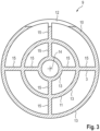
- the heat exchanger 11 can be made of metal, plastic or ceramic, for example. It is usually designed as a thin layer (usually 2 mm or less). To form a large surface, the heat exchanger 11 can be made as shown in FIG 3 For example, several rings 13 can be formed which run around a common axis 14 and are connected to one another via radially extending struts 15 of the heat exchanger 11. The number of rings 13 and the number of struts 15 are only examples. Other designs are also possible.
- the respective phase change material 10 changes its phase state at a respective transition temperature.
- the transition temperature must be in a range between the temperature outside the building 1 and the temperature inside the building 1. Otherwise, no phase change would take place during operation.
- the transition temperature can be between -2 °C and 18 °C.
- the temperature values mentioned are only examples.
- the transition temperatures of the phase change materials are preferably different from one another in at least one pair of sections 8.
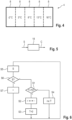
- the transition temperatures are as shown in FIG 4 staggered, ie they increase or decrease continuously (depending on the flow direction of the air stream 7), ie at least monotonously, preferably even strictly monotonously.
- additional conventional sections 8 can be present.
- At least one of the ventilation devices 3 arranged in the building 1 has a fan device 16. However, at least one other of the ventilation devices 3 does not have a fan device. For this reason, the fan device 16 is in FIG 3 only shown in dashed lines. If the respective ventilation device 3 has a fan device 16, the fan device 16 is preferably arranged in the area of the ventilation opening 5, i.e. in the area of the ventilation opening 5 which is located on the outside of the wall 2.
- a ventilation device 3 with a fan device 16 is provided according to FIG 5 controlled by a control device 18. If the sensor 17 is not present, a purely time-controlled mode of operation can take place. However, such a design does not fall under the scope of the claims. In this case, the control device 18 can carry out a sequence of steps which is subsequently described in connection with FIG 6 is explained.
- the control device 18 checks in a step S1 whether an accumulated time T has exceeded a time limit T0. If this is the case, the control device 18 inverts the conveying direction of the fan device 16 and thus the direction of the air flow 7 in a step S2 by means of a corresponding control signal C. If the fan device 16 is operated with a positive conveying direction was, the negative conveying direction is now assumed. If, on the other hand, the fan device 16 was operated with a negative conveying direction, the positive conveying direction is now assumed. Without limiting the generality, it can be assumed that the positive conveying direction corresponds to the air flow 7, i.e. an air flow directed from the inside to the outside.
- step S2 the control device 18 sets the accumulated time T to the value 0 in a step S3. If, on the other hand, the accumulated time T has not exceeded the time limit T0, the control device 18 increments the accumulated time T in a step S4. From both step S3 and step S4, the control device 18 returns to step S1.
- the time limit T0 can be determined as required. It is preferably in the range of several minutes, in particular at least 5 minutes and usually a maximum of 10 minutes.
- the flow direction of the air flow 7 is also determined by controlling the fan device 16 of the ventilation device 3 with fan device 16. If there are several ventilation devices 3 that have a fan device 16, the control of the fan devices 16 of the corresponding ventilation devices should be coordinated.
- the ventilation device 3 is also assigned a sensor 17.
- the sensor 17 is preferably arranged in the area of the ventilation opening 6, i.e. in the area of the ventilation opening 6, which is located on the inside of the respective wall 2. It can also be installed at another location in the ventilation system 3 or outside the ventilation device 3. A concentration of volatile organic compounds is detected by means of the sensor 17. Alternatively or additionally, the air humidity is detected by means of the sensor 17.
- a time-controlled mode of operation takes place in accordance with steps S1 to S4.
- steps S5 to S7 are present.
- the control device 18 receives the sensor signal S from the sensor 17.
- the control device 18 is connected to the sensor 17 via data technology. The connection can be wired or wireless.
- the control device 18 checks whether, based on the sensor signal S, it detects a humidity and/or a concentration of the volatile organic compounds above a limit value. If this is not the case, the control device 18 goes to step S1 and the time-controlled mode of operation already explained takes place.
- control device 18 If, on the other hand, the control device 18 detects a humidity and/or a concentration of the volatile organic compounds above the limit value, it sets a defined flow direction in step S7. As a rule, the set flow direction will be such that the air flow 7 for this ventilation device 3 is directed from the inside to the outside.
- control of the fan device 16 can also be completely suppressed in step S7.
- control of the fan device 16 is never permitted in step S7, on the basis of which the control device 18 operates the fan device 16 with a flow direction from the first to the second ventilation opening 5, 6.
- a throttle device can also be arranged, by means of which an effective cross-section of the ventilation duct 4 can be varied.
- the throttle device is not shown in the FIGS.
- the throttle device can be designed, for example, as shown in the EP 3 165 701 A1 or in the EP 3 165 702 A1 Alternatively, the throttle device can be actively controlled, in particular depending on a noise level outside the building.
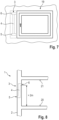
- the ventilation device 3 is, as already mentioned, arranged in a wall 2 of a room of the building 1. It can be installed as shown in the FIGS 7 and 8 in particular in or on a window 19 of the building 1 (or equivalently a door of the building 1).
- the room itself has a floor 20 and a ceiling 21.
- the ventilation device 3 is preferably arranged and designed such that the ventilation opening 6 - i.e. the ventilation opening 6 facing the room, which is located on the inside of the wall 2 - is arranged at least 1.80 m, in particular at least 2.00 m, above the floor 20.
- the ventilation opening 5 - i.e. the ventilation opening 5 facing the environment, which is located on the outside of the respective wall 2 - can in principle be arranged at any height, in particular at the same height, higher up or lower down.
- the ventilation duct 4 can, as in the FIGS 7 and 8 indicated by dashed lines, in particular run vertically and be arranged further down than the ventilation opening 6 facing the inside of the room.
- the present invention has many advantages. In particular, it provides significantly more cost-effective, significantly more flexible and significantly more convenient solutions for implementing pendulum fans.
Landscapes
- Engineering & Computer Science (AREA)
- Chemical & Material Sciences (AREA)
- Combustion & Propulsion (AREA)
- Mechanical Engineering (AREA)
- General Engineering & Computer Science (AREA)
- Ventilation (AREA)
Applications Claiming Priority (2)
| Application Number | Priority Date | Filing Date | Title |
|---|---|---|---|
| DE202021003488 | 2021-11-12 | ||
| DE202022100099.9U DE202022100099U1 (de) | 2021-11-12 | 2022-01-10 | Lüftungseinrichtung mit Wärmespeicher mit Phasenumwandlung für ein Gebäude |
Publications (3)
| Publication Number | Publication Date |
|---|---|
| EP4180732A1 EP4180732A1 (de) | 2023-05-17 |
| EP4180732C0 EP4180732C0 (de) | 2024-06-12 |
| EP4180732B1 true EP4180732B1 (de) | 2024-06-12 |
Family
ID=84329348
Family Applications (1)
| Application Number | Title | Priority Date | Filing Date |
|---|---|---|---|
| EP22020531.4A Active EP4180732B1 (de) | 2021-11-12 | 2022-11-04 | Kombination einer lüftungseinrichtung für ein gebäude mit einer weiteren lüftungseinrichtung |
Country Status (2)
| Country | Link |
|---|---|
| EP (1) | EP4180732B1 (pl) |
| PL (1) | PL4180732T3 (pl) |
Families Citing this family (1)
| Publication number | Priority date | Publication date | Assignee | Title |
|---|---|---|---|---|
| GB2641034A (en) * | 2024-05-13 | 2025-11-19 | Volution Ventilation Group Ltd | Ventilation heat recovery unit |
Family Cites Families (9)
| Publication number | Priority date | Publication date | Assignee | Title |
|---|---|---|---|---|
| NO137706L (pl) * | 1974-01-21 | |||
| NL9300081A (nl) * | 1993-01-15 | 1994-08-01 | Compri Aluminium | Zelf-regelend ventilatierooster. |
| CN201028730Y (zh) * | 2007-01-29 | 2008-02-27 | 钟章水 | 一种自动换热式建筑防噪音通风装置 |
| DE102008057787B3 (de) * | 2008-11-17 | 2010-03-04 | Albert Bauer | Regelvorrichtung für raumlufttechnische Anlagen |
| EP3121527B1 (de) * | 2015-07-21 | 2020-03-18 | Aereco GmbH | Lüftungsvorrichtung zur lüftung von gebäuderäumen |
| DE102015014351A1 (de) | 2015-11-05 | 2017-05-11 | Albert Regensburger | Belüftungselement für Fenster mit als Schikane wirkender Klappe |
| DE102015014268A1 (de) | 2015-11-05 | 2017-05-11 | Albert Regensburger | Fensterelement mit optimierter Anordnung einer Zwangslüftung |
| DE102016211200A1 (de) * | 2016-06-22 | 2017-12-28 | LUNOS Lüftungstechnik GmbH für Raumluftsysteme | Lüftungsgerät mit schwenkbarem Filter |
| US20200393152A1 (en) * | 2019-05-24 | 2020-12-17 | Natural Air E-Controls, Llc | Adaptive, responsive, dynamic building ventilation control system |
-
2022
- 2022-11-04 PL PL22020531.4T patent/PL4180732T3/pl unknown
- 2022-11-04 EP EP22020531.4A patent/EP4180732B1/de active Active
Also Published As
| Publication number | Publication date |
|---|---|
| EP4180732A1 (de) | 2023-05-17 |
| EP4180732C0 (de) | 2024-06-12 |
| PL4180732T3 (pl) | 2024-09-23 |
Similar Documents
| Publication | Publication Date | Title |
|---|---|---|
| EP2594725B1 (de) | Fenster | |
| EP2660525A2 (de) | Belüftungsvorrichtung | |
| DE202022100099U1 (de) | Lüftungseinrichtung mit Wärmespeicher mit Phasenumwandlung für ein Gebäude | |
| EP2136147B1 (de) | Verfahren und Einrichtung zur Regelung der Temperatur, der Feuchtigkeit und des Kohlendioxidanteils der Luft in Räumen | |
| EP2947396B1 (de) | Verfahren zum belüften eines raumes sowie lüftungsanlage hierfür | |
| DE202017103341U1 (de) | Ventilationsanlage | |
| DE102011080358A1 (de) | Einbauprofil | |
| EP2850272A2 (de) | Rahmenlueftungsgeraet, fensteranordnung und eingebautes fenster mit lüftungsgeraet zum lueften und zum erhalt der regulaeren verglasungsgroesse und auch rahmenabmessungen | |
| EP2664865B1 (de) | Lufttechnisches Gerät zur Be- und Entlüftung sowie Be- und Entlüftungsverfahren | |
| DE102010006455B4 (de) | Verfahren, Steuereinrichtung und -system zur Be-und Entlüftung eines Gesamtraums mit mehreren Teilräumen, insbesondere eines eine Wohneinheit bildenden Gesamtraums | |
| DE102011002734A1 (de) | Steuerung für Raumlüftungsvorrichtung mit Wärmerückgewinnung | |
| EP4180732A1 (de) | Lüftungseinrichtung mit wärmespeicher ohne ventilatoreinrichtung | |
| WO2017020889A2 (de) | VERFAHREN ZUM BETRIEB EINER DEZENTRALEN VORRICHTUNG ZUR KONTROLLIERTEN WOHNRAUMLÜFTUNG SOWIE VERFAHRENSGEMÄß AUSGEBILDETE WOHNRAUMLÜFTUNGSVORRICHTUNG | |
| DE202014011129U1 (de) | Lüftungsgerät und Regelungseinrichtung für ein Lüftungsgerät | |
| DE19639128A1 (de) | Lüftungswärmetauscher | |
| EP4206552B1 (de) | Lüftungsgerät | |
| EP3916314B1 (de) | Lüftungssystem | |
| DE10214239A1 (de) | Vorrichtung zur Belüftung von Räumen | |
| DE8417444U1 (de) | Gerät zum Anbau an Fenster und Türen zur Verbesserung der Klimawerte in Aufenthaltsräumen | |
| EP2180269B1 (de) | Hybride Raumlüftungsvorrichtung | |
| DE3121080A1 (de) | Luftauslass mit verstellbaren strahlleiteinrichtungen | |
| EP3599334A1 (de) | Fassadenelement mit einem luftgütesensor | |
| AT524782B1 (de) | Verschlussvorrichtung für eine Wandöffnung | |
| EP3795914B1 (de) | Mehrraumgebäude-lüftungsanlage | |
| EP0877209A2 (de) | Belüftungsvorrichtung für ein Gebäude |
Legal Events
| Date | Code | Title | Description |
|---|---|---|---|
| PUAI | Public reference made under article 153(3) epc to a published international application that has entered the european phase |
Free format text: ORIGINAL CODE: 0009012 |
|
| STAA | Information on the status of an ep patent application or granted ep patent |
Free format text: STATUS: THE APPLICATION HAS BEEN PUBLISHED |
|
| AK | Designated contracting states |
Kind code of ref document: A1 Designated state(s): AL AT BE BG CH CY CZ DE DK EE ES FI FR GB GR HR HU IE IS IT LI LT LU LV MC ME MK MT NL NO PL PT RO RS SE SI SK SM TR |
|
| STAA | Information on the status of an ep patent application or granted ep patent |
Free format text: STATUS: REQUEST FOR EXAMINATION WAS MADE |
|
| 17P | Request for examination filed |
Effective date: 20230531 |
|
| RBV | Designated contracting states (corrected) |
Designated state(s): AL AT BE BG CH CY CZ DE DK EE ES FI FR GB GR HR HU IE IS IT LI LT LU LV MC ME MK MT NL NO PL PT RO RS SE SI SK SM TR |
|
| GRAP | Despatch of communication of intention to grant a patent |
Free format text: ORIGINAL CODE: EPIDOSNIGR1 |
|
| STAA | Information on the status of an ep patent application or granted ep patent |
Free format text: STATUS: GRANT OF PATENT IS INTENDED |
|
| RIC1 | Information provided on ipc code assigned before grant |
Ipc: F24F 130/40 20180101ALN20240103BHEP Ipc: F24F 12/00 20060101ALN20240103BHEP Ipc: F24F 7/00 20210101ALN20240103BHEP Ipc: F24F 11/00 20180101ALI20240103BHEP Ipc: F24F 7/06 20060101AFI20240103BHEP |
|
| RIC1 | Information provided on ipc code assigned before grant |
Ipc: F24F 130/40 20180101ALN20240112BHEP Ipc: F24F 12/00 20060101ALN20240112BHEP Ipc: F24F 7/00 20210101ALN20240112BHEP Ipc: F24F 11/00 20180101ALI20240112BHEP Ipc: F24F 7/06 20060101AFI20240112BHEP |
|
| GRAS | Grant fee paid |
Free format text: ORIGINAL CODE: EPIDOSNIGR3 |
|
| INTG | Intention to grant announced |
Effective date: 20240205 |
|
| GRAA | (expected) grant |
Free format text: ORIGINAL CODE: 0009210 |
|
| STAA | Information on the status of an ep patent application or granted ep patent |
Free format text: STATUS: THE PATENT HAS BEEN GRANTED |
|
| AK | Designated contracting states |
Kind code of ref document: B1 Designated state(s): AL AT BE BG CH CY CZ DE DK EE ES FI FR GB GR HR HU IE IS IT LI LT LU LV MC ME MK MT NL NO PL PT RO RS SE SI SK SM TR |
|
| REG | Reference to a national code |
Ref country code: GB Ref legal event code: FG4D Free format text: NOT ENGLISH |
|
| REG | Reference to a national code |
Ref country code: CH Ref legal event code: EP |
|
| REG | Reference to a national code |
Ref country code: IE Ref legal event code: FG4D Free format text: LANGUAGE OF EP DOCUMENT: GERMAN |
|
| REG | Reference to a national code |
Ref country code: DE Ref legal event code: R096 Ref document number: 502022001003 Country of ref document: DE |
|
| U01 | Request for unitary effect filed |
Effective date: 20240612 |
|
| U07 | Unitary effect registered |
Designated state(s): AT BE BG DE DK EE FI FR IT LT LU LV MT NL PT SE SI Effective date: 20240621 |
|
| PG25 | Lapsed in a contracting state [announced via postgrant information from national office to epo] |
Ref country code: HR Free format text: LAPSE BECAUSE OF FAILURE TO SUBMIT A TRANSLATION OF THE DESCRIPTION OR TO PAY THE FEE WITHIN THE PRESCRIBED TIME-LIMIT Effective date: 20240612 |
|
| PG25 | Lapsed in a contracting state [announced via postgrant information from national office to epo] |
Ref country code: GR Free format text: LAPSE BECAUSE OF FAILURE TO SUBMIT A TRANSLATION OF THE DESCRIPTION OR TO PAY THE FEE WITHIN THE PRESCRIBED TIME-LIMIT Effective date: 20240913 |
|
| U20 | Renewal fee for the european patent with unitary effect paid |
Year of fee payment: 3 Effective date: 20240909 |
|
| PG25 | Lapsed in a contracting state [announced via postgrant information from national office to epo] |
Ref country code: ES Free format text: LAPSE BECAUSE OF FAILURE TO SUBMIT A TRANSLATION OF THE DESCRIPTION OR TO PAY THE FEE WITHIN THE PRESCRIBED TIME-LIMIT Effective date: 20240612 |
|
| PG25 | Lapsed in a contracting state [announced via postgrant information from national office to epo] |
Ref country code: NO Free format text: LAPSE BECAUSE OF FAILURE TO SUBMIT A TRANSLATION OF THE DESCRIPTION OR TO PAY THE FEE WITHIN THE PRESCRIBED TIME-LIMIT Effective date: 20240912 Ref country code: HR Free format text: LAPSE BECAUSE OF FAILURE TO SUBMIT A TRANSLATION OF THE DESCRIPTION OR TO PAY THE FEE WITHIN THE PRESCRIBED TIME-LIMIT Effective date: 20240612 Ref country code: GR Free format text: LAPSE BECAUSE OF FAILURE TO SUBMIT A TRANSLATION OF THE DESCRIPTION OR TO PAY THE FEE WITHIN THE PRESCRIBED TIME-LIMIT Effective date: 20240913 Ref country code: ES Free format text: LAPSE BECAUSE OF FAILURE TO SUBMIT A TRANSLATION OF THE DESCRIPTION OR TO PAY THE FEE WITHIN THE PRESCRIBED TIME-LIMIT Effective date: 20240612 Ref country code: RS Free format text: LAPSE BECAUSE OF FAILURE TO SUBMIT A TRANSLATION OF THE DESCRIPTION OR TO PAY THE FEE WITHIN THE PRESCRIBED TIME-LIMIT Effective date: 20240912 |
|
| PG25 | Lapsed in a contracting state [announced via postgrant information from national office to epo] |
Ref country code: IS Free format text: LAPSE BECAUSE OF FAILURE TO SUBMIT A TRANSLATION OF THE DESCRIPTION OR TO PAY THE FEE WITHIN THE PRESCRIBED TIME-LIMIT Effective date: 20241012 |
|
| PG25 | Lapsed in a contracting state [announced via postgrant information from national office to epo] |
Ref country code: CZ Free format text: LAPSE BECAUSE OF FAILURE TO SUBMIT A TRANSLATION OF THE DESCRIPTION OR TO PAY THE FEE WITHIN THE PRESCRIBED TIME-LIMIT Effective date: 20240612 |
|
| PG25 | Lapsed in a contracting state [announced via postgrant information from national office to epo] |
Ref country code: RO Free format text: LAPSE BECAUSE OF FAILURE TO SUBMIT A TRANSLATION OF THE DESCRIPTION OR TO PAY THE FEE WITHIN THE PRESCRIBED TIME-LIMIT Effective date: 20240612 Ref country code: SK Free format text: LAPSE BECAUSE OF FAILURE TO SUBMIT A TRANSLATION OF THE DESCRIPTION OR TO PAY THE FEE WITHIN THE PRESCRIBED TIME-LIMIT Effective date: 20240612 |
|
| PG25 | Lapsed in a contracting state [announced via postgrant information from national office to epo] |
Ref country code: SM Free format text: LAPSE BECAUSE OF FAILURE TO SUBMIT A TRANSLATION OF THE DESCRIPTION OR TO PAY THE FEE WITHIN THE PRESCRIBED TIME-LIMIT Effective date: 20240612 |
|
| PG25 | Lapsed in a contracting state [announced via postgrant information from national office to epo] |
Ref country code: SM Free format text: LAPSE BECAUSE OF FAILURE TO SUBMIT A TRANSLATION OF THE DESCRIPTION OR TO PAY THE FEE WITHIN THE PRESCRIBED TIME-LIMIT Effective date: 20240612 Ref country code: SK Free format text: LAPSE BECAUSE OF FAILURE TO SUBMIT A TRANSLATION OF THE DESCRIPTION OR TO PAY THE FEE WITHIN THE PRESCRIBED TIME-LIMIT Effective date: 20240612 Ref country code: RO Free format text: LAPSE BECAUSE OF FAILURE TO SUBMIT A TRANSLATION OF THE DESCRIPTION OR TO PAY THE FEE WITHIN THE PRESCRIBED TIME-LIMIT Effective date: 20240612 Ref country code: IS Free format text: LAPSE BECAUSE OF FAILURE TO SUBMIT A TRANSLATION OF THE DESCRIPTION OR TO PAY THE FEE WITHIN THE PRESCRIBED TIME-LIMIT Effective date: 20241012 Ref country code: CZ Free format text: LAPSE BECAUSE OF FAILURE TO SUBMIT A TRANSLATION OF THE DESCRIPTION OR TO PAY THE FEE WITHIN THE PRESCRIBED TIME-LIMIT Effective date: 20240612 |
|
| PLBE | No opposition filed within time limit |
Free format text: ORIGINAL CODE: 0009261 |
|
| STAA | Information on the status of an ep patent application or granted ep patent |
Free format text: STATUS: NO OPPOSITION FILED WITHIN TIME LIMIT |
|
| 26N | No opposition filed |
Effective date: 20250313 |
|
| PG25 | Lapsed in a contracting state [announced via postgrant information from national office to epo] |
Ref country code: MC Free format text: LAPSE BECAUSE OF FAILURE TO SUBMIT A TRANSLATION OF THE DESCRIPTION OR TO PAY THE FEE WITHIN THE PRESCRIBED TIME-LIMIT Effective date: 20240612 |
|
| PG25 | Lapsed in a contracting state [announced via postgrant information from national office to epo] |
Ref country code: IE Free format text: LAPSE BECAUSE OF NON-PAYMENT OF DUE FEES Effective date: 20241104 |
|
| U20 | Renewal fee for the european patent with unitary effect paid |
Year of fee payment: 4 Effective date: 20250924 |
|
| REG | Reference to a national code |
Ref country code: CH Ref legal event code: U11 Free format text: ST27 STATUS EVENT CODE: U-0-0-U10-U11 (AS PROVIDED BY THE NATIONAL OFFICE) Effective date: 20251201 |
|
| U1N | Appointed representative for the unitary patent procedure changed after the registration of the unitary effect |
Representative=s name: PATENTANWAELTE BRESSEL UND PARTNER MBB; DE |
|
| PGFP | Annual fee paid to national office [announced via postgrant information from national office to epo] |
Ref country code: CH Payment date: 20251201 Year of fee payment: 4 |
|
| PGFP | Annual fee paid to national office [announced via postgrant information from national office to epo] |
Ref country code: PL Payment date: 20251024 Year of fee payment: 4 |
|
| PG25 | Lapsed in a contracting state [announced via postgrant information from national office to epo] |
Ref country code: HU Free format text: LAPSE BECAUSE OF FAILURE TO SUBMIT A TRANSLATION OF THE DESCRIPTION OR TO PAY THE FEE WITHIN THE PRESCRIBED TIME-LIMIT; INVALID AB INITIO Effective date: 20221104 |
|
| PG25 | Lapsed in a contracting state [announced via postgrant information from national office to epo] |
Ref country code: CY Free format text: LAPSE BECAUSE OF FAILURE TO SUBMIT A TRANSLATION OF THE DESCRIPTION OR TO PAY THE FEE WITHIN THE PRESCRIBED TIME-LIMIT; INVALID AB INITIO Effective date: 20221104 |