EP4180741A1 - System zur versteifung einer struktur - Google Patents
System zur versteifung einer struktur Download PDFInfo
- Publication number
- EP4180741A1 EP4180741A1 EP22207227.4A EP22207227A EP4180741A1 EP 4180741 A1 EP4180741 A1 EP 4180741A1 EP 22207227 A EP22207227 A EP 22207227A EP 4180741 A1 EP4180741 A1 EP 4180741A1
- Authority
- EP
- European Patent Office
- Prior art keywords
- tie rods
- connecting element
- crosspieces
- extension
- pair
- Prior art date
- Legal status (The legal status is an assumption and is not a legal conclusion. Google has not performed a legal analysis and makes no representation as to the accuracy of the status listed.)
- Withdrawn
Links
Images




Classifications
-
- F—MECHANICAL ENGINEERING; LIGHTING; HEATING; WEAPONS; BLASTING
- F24—HEATING; RANGES; VENTILATING
- F24S—SOLAR HEAT COLLECTORS; SOLAR HEAT SYSTEMS
- F24S25/00—Arrangement of stationary mountings or supports for solar heat collector modules
- F24S25/10—Arrangement of stationary mountings or supports for solar heat collector modules extending in directions away from a supporting surface
- F24S25/13—Profile arrangements, e.g. trusses
-
- G—PHYSICS
- G01—MEASURING; TESTING
- G01J—MEASUREMENT OF INTENSITY, VELOCITY, SPECTRAL CONTENT, POLARISATION, PHASE OR PULSE CHARACTERISTICS OF INFRARED, VISIBLE OR ULTRAVIOLET LIGHT; COLORIMETRY; RADIATION PYROMETRY
- G01J1/00—Photometry, e.g. photographic exposure meter
- G01J1/02—Details
- G01J1/04—Optical or mechanical part supplementary adjustable parts
- G01J1/0403—Mechanical elements; Supports for optical elements; Scanning arrangements
-
- F—MECHANICAL ENGINEERING; LIGHTING; HEATING; WEAPONS; BLASTING
- F24—HEATING; RANGES; VENTILATING
- F24S—SOLAR HEAT COLLECTORS; SOLAR HEAT SYSTEMS
- F24S25/00—Arrangement of stationary mountings or supports for solar heat collector modules
- F24S25/50—Arrangement of stationary mountings or supports for solar heat collector modules comprising elongate non-rigid elements, e.g. straps, wires or ropes
-
- E—FIXED CONSTRUCTIONS
- E04—BUILDING
- E04C—STRUCTURAL ELEMENTS; BUILDING MATERIALS
- E04C3/00—Structural elongated elements designed for load-supporting
- E04C3/02—Joists; Girders, trusses, or trusslike structures, e.g. prefabricated; Lintels; Transoms; Braces
- E04C3/04—Joists; Girders, trusses, or trusslike structures, e.g. prefabricated; Lintels; Transoms; Braces of metal
- E04C3/08—Joists; Girders, trusses, or trusslike structures, e.g. prefabricated; Lintels; Transoms; Braces of metal with apertured web, e.g. with a web consisting of bar-like components; Honeycomb girders
-
- F—MECHANICAL ENGINEERING; LIGHTING; HEATING; WEAPONS; BLASTING
- F16—ENGINEERING ELEMENTS AND UNITS; GENERAL MEASURES FOR PRODUCING AND MAINTAINING EFFECTIVE FUNCTIONING OF MACHINES OR INSTALLATIONS; THERMAL INSULATION IN GENERAL
- F16B—DEVICES FOR FASTENING OR SECURING CONSTRUCTIONAL ELEMENTS OR MACHINE PARTS TOGETHER, e.g. NAILS, BOLTS, CIRCLIPS, CLAMPS, CLIPS OR WEDGES; JOINTS OR JOINTING
- F16B2/00—Friction-grip releasable fastenings
-
- F—MECHANICAL ENGINEERING; LIGHTING; HEATING; WEAPONS; BLASTING
- F16—ENGINEERING ELEMENTS AND UNITS; GENERAL MEASURES FOR PRODUCING AND MAINTAINING EFFECTIVE FUNCTIONING OF MACHINES OR INSTALLATIONS; THERMAL INSULATION IN GENERAL
- F16B—DEVICES FOR FASTENING OR SECURING CONSTRUCTIONAL ELEMENTS OR MACHINE PARTS TOGETHER, e.g. NAILS, BOLTS, CIRCLIPS, CLAMPS, CLIPS OR WEDGES; JOINTS OR JOINTING
- F16B7/00—Connections of rods or tubes, e.g. of non-circular section, mutually, including resilient connections
- F16B7/04—Clamping or clipping connections
- F16B7/0406—Clamping or clipping connections for rods or tubes being coaxial
-
- F—MECHANICAL ENGINEERING; LIGHTING; HEATING; WEAPONS; BLASTING
- F16—ENGINEERING ELEMENTS AND UNITS; GENERAL MEASURES FOR PRODUCING AND MAINTAINING EFFECTIVE FUNCTIONING OF MACHINES OR INSTALLATIONS; THERMAL INSULATION IN GENERAL
- F16B—DEVICES FOR FASTENING OR SECURING CONSTRUCTIONAL ELEMENTS OR MACHINE PARTS TOGETHER, e.g. NAILS, BOLTS, CIRCLIPS, CLAMPS, CLIPS OR WEDGES; JOINTS OR JOINTING
- F16B7/00—Connections of rods or tubes, e.g. of non-circular section, mutually, including resilient connections
- F16B7/18—Connections of rods or tubes, e.g. of non-circular section, mutually, including resilient connections using screw-thread elements
-
- F—MECHANICAL ENGINEERING; LIGHTING; HEATING; WEAPONS; BLASTING
- F24—HEATING; RANGES; VENTILATING
- F24S—SOLAR HEAT COLLECTORS; SOLAR HEAT SYSTEMS
- F24S25/00—Arrangement of stationary mountings or supports for solar heat collector modules
- F24S25/70—Arrangement of stationary mountings or supports for solar heat collector modules with means for adjusting the final position or orientation of supporting elements in relation to each other or to a mounting surface; with means for compensating mounting tolerances
-
- G—PHYSICS
- G05—CONTROLLING; REGULATING
- G05D—SYSTEMS FOR CONTROLLING OR REGULATING NON-ELECTRIC VARIABLES
- G05D3/00—Control of position or direction
- G05D3/10—Control of position or direction without using feedback
- G05D3/105—Solar tracker
-
- H—ELECTRICITY
- H02—GENERATION; CONVERSION OR DISTRIBUTION OF ELECTRIC POWER
- H02S—GENERATION OF ELECTRIC POWER BY CONVERSION OF INFRARED RADIATION, VISIBLE LIGHT OR ULTRAVIOLET LIGHT, e.g. USING PHOTOVOLTAIC [PV] MODULES
- H02S20/00—Supporting structures for PV modules
- H02S20/30—Supporting structures being movable or adjustable, e.g. for angle adjustment
- H02S20/32—Supporting structures being movable or adjustable, e.g. for angle adjustment specially adapted for solar tracking
-
- E—FIXED CONSTRUCTIONS
- E04—BUILDING
- E04C—STRUCTURAL ELEMENTS; BUILDING MATERIALS
- E04C3/00—Structural elongated elements designed for load-supporting
- E04C3/02—Joists; Girders, trusses, or trusslike structures, e.g. prefabricated; Lintels; Transoms; Braces
- E04C3/04—Joists; Girders, trusses, or trusslike structures, e.g. prefabricated; Lintels; Transoms; Braces of metal
- E04C2003/0486—Truss like structures composed of separate truss elements
- E04C2003/0495—Truss like structures composed of separate truss elements the truss elements being located in several non-parallel surfaces
-
- F—MECHANICAL ENGINEERING; LIGHTING; HEATING; WEAPONS; BLASTING
- F24—HEATING; RANGES; VENTILATING
- F24S—SOLAR HEAT COLLECTORS; SOLAR HEAT SYSTEMS
- F24S25/00—Arrangement of stationary mountings or supports for solar heat collector modules
- F24S2025/01—Special support components; Methods of use
- F24S2025/019—Means for accommodating irregularities on mounting surface; Tolerance compensation means
-
- G—PHYSICS
- G01—MEASURING; TESTING
- G01J—MEASUREMENT OF INTENSITY, VELOCITY, SPECTRAL CONTENT, POLARISATION, PHASE OR PULSE CHARACTERISTICS OF INFRARED, VISIBLE OR ULTRAVIOLET LIGHT; COLORIMETRY; RADIATION PYROMETRY
- G01J1/00—Photometry, e.g. photographic exposure meter
- G01J1/42—Photometry, e.g. photographic exposure meter using electric radiation detectors
- G01J2001/4266—Photometry, e.g. photographic exposure meter using electric radiation detectors for measuring solar light
-
- Y—GENERAL TAGGING OF NEW TECHNOLOGICAL DEVELOPMENTS; GENERAL TAGGING OF CROSS-SECTIONAL TECHNOLOGIES SPANNING OVER SEVERAL SECTIONS OF THE IPC; TECHNICAL SUBJECTS COVERED BY FORMER USPC CROSS-REFERENCE ART COLLECTIONS [XRACs] AND DIGESTS
- Y02—TECHNOLOGIES OR APPLICATIONS FOR MITIGATION OR ADAPTATION AGAINST CLIMATE CHANGE
- Y02E—REDUCTION OF GREENHOUSE GAS [GHG] EMISSIONS, RELATED TO ENERGY GENERATION, TRANSMISSION OR DISTRIBUTION
- Y02E10/00—Energy generation through renewable energy sources
- Y02E10/40—Solar thermal energy, e.g. solar towers
- Y02E10/47—Mountings or tracking
Definitions
- the present invention generally relates to the tensioning of rigid tie rods on structures, and more particularly to a system for stiffening a structure, a method for stiffening a structure using said system, a lattice structure comprising said system and a solar tracker comprising said structure.
- tie rods are used in order to stiffen the assembly.
- tie rods the tensioning of which is made possible by turnbuckles (also called turnbuckles).
- Such a device typically comprises a first tie rod having a fixed end and an end provided with a right-hand thread, a second tie rod having a fixed end and an end provided with a left-hand thread, and a central sleeve onto which the threaded ends are screwed. first and second tie rods. The rotation of the central sleeve then causes the tensioning of the first and second tie rods.
- the document WO 2018/033495 in the name of the Applicant, describes a lattice structure comprising tie rods, said lattice structure serving as a support structure for a table of a solar tracker.
- the constituent elements of the structure to which the tie rods are fixed are manufactured according to manufacturing tolerances, thus substantially varying the distance between the points of attachment of the tie rods to the structure.
- the compensation for these tolerance differences cannot be made by introducing play at the level of the points of fixing, the risk of buckling of the tie rods becoming high in these circumstances.
- they In order to avoid the buckling of the tie rods, they must preferably be fixed with a slight pre-tension in traction.
- the use of a thread/nut system at the end of the tie rod solves this problem.
- this solution proves to be costly and requires considerable assembly time.
- the document WO 2021/009425 in the name of the Applicant, describes a tie rod able to be fixed at two fixing points of a structure by means of two fixing screws, said tie rod comprising a longitudinal body provided with a first fixing end comprising a first circular opening and a second attachment end comprising a second circular opening.
- Said tie rod comprises a washer comprising a cylindrical outer casing body and provided with an eccentric through hole, said washer being received concentrically in the second circular opening and movable in rotation in said second circular opening so as to modify the position of the eccentric orifice to vary a fixing center distance between said eccentric orifice and the first circular opening.
- An object of the present invention is to improve the systems for tensioning the tie rods, in particular that described in the document WO 2021/009425 , and in particular to better control or even precisely quantify the tension applied to the tie rods and reduce the time required to tension the tie rods, in order to respond to the problem of compensating for tolerance differences and mechanically reinforcing the structure, in particular vis-à-vis against deformations by bending and/or torsion.
- the connecting element is in said inactive configuration before deformation by the actuator and in said active configuration after deformation by the actuator.
- the deformation of the connecting element allows passage from a first state of tension of the tie rods to a second state of tension, different from the first. It is thus possible to modify the tension in the tie rods in a simple and reproducible way.
- the second tension state corresponds to a tensile tension state of the tie rods.
- the tensile tension in the tie rods is higher in the second tension state compared to the first tension state.
- the system according to the invention can allow the tensile tensioning of the tie rods by deformation of the connecting element (i.e. passage from the inactive configuration to the active configuration), so as to mechanically reinforce the structure.
- the first state of tension may correspond to a state in which no tension is applied to the tie rods or a state of slight tension in compression of the tie rods.
- This first state of tension can make it easier to mount the tie rods on the structure and the connecting element.
- the second voltage state may be predetermined. This means that the second state of tension may correspond to a predetermined tensile tension value of the tie rods, in particular sufficient to ensure the mechanical reinforcement of the structure.
- the system according to the invention can make it possible to quantify the tensile tension applied to the tie rods.
- one of the tie rods of the pair of tie rods is fixed by its second end at a first attachment point of the connecting element and the other tie rod of the pair of tie rods is fixed by its second end at a second attachment point of the connecting element.
- the deformation of the connecting element during its passage from the inactive configuration to the active configuration preferably leads to a shortening of the distance between the first and second attachment points of the connecting element, this distance being measured along a line passing through the first and second attachment points of the connecting element.
- Such a deformation of the connecting element makes it possible to apply a tensile force to each tie rod of the pair of tie rods.
- the link element can be plastically deformable and the actuator can be configured to plastically deform the link element.
- the link element can be elastically deformable and the actuator can be configured to elastically deform the link element.
- the actuator can be configured to exert a constraint on the connecting element to deform it and thus cause it to pass from the inactive configuration to the active configuration.
- the connecting element can be plastically or elastically deformable.
- the actuator can also be configured to release the stress exerted on the connecting element to enable it to return to its initial state, ie before deformation, and thus cause it to pass from the active configuration to the inactive configuration.
- the connecting element is preferably elastically deformable and the actuator is preferably configured to elastically deform the connecting element.
- the stress exerted by the actuator on the connecting element can be a tightening of the connecting element, in particular against the actuator.
- the connecting element can be made of any type of material deformable by the actuator.
- the connecting element is for example made of a metallic material, preferably steel or stainless steel.
- the thickness of the connecting element can be between 2 and 4 mm.
- the material and/or the thickness of the connecting element are chosen so as to give the connecting element sufficient ductility to allow its deformation without breaking.
- the connecting element preferably extends in a first plane and is deformable in a second plane, perpendicular to the first plane.
- Each tie rod of the pair or pairs of tie rods preferably extends in the same plane as the connecting element (i.e. the first plane) or in a parallel plane.
- tie rods of the pair or of each pair of tie rods can be located in the extension of one another.
- tie rods of the pair or of each pair of tie rods are preferably aligned.
- Each tie rod of the pair or pairs of tie rods is preferably rigid.
- Each tie rod of the pair or pairs of tie rods can be made of a metallic material, for example steel or stainless steel.
- Each tie rod of the pair or pairs of tie rods may comprise a body, for example a rigid metal bar, extending along the longitudinal axis of the tie rod, said body being provided with said first end which is fixed to the structure and with said second end which is fixed to the connecting element.
- the connecting element may comprise a pair of arms, the arms notably comprising proximal ends connected to the center of the connecting element and distal ends comprising the attachment points.
- the arms of the pair of arms of the connecting element can be located in the extension of one another.
- the arms of the pair of arms of the connecting element are preferably aligned.
- Each arm of the pair of arms of the connecting element may be a plate, in particular having a generally triangular shape, with for example a vertex of the triangle as the proximal end of the arm connected to said center of the connecting element and a side opposite said apex as the distal end of the arm having said attachment point.
- the system can comprise at least two pairs of tie rods, each tie rod preferably comprising a first end fixed to the structure and a second end fixed to the connecting element.
- each tie rod is attached to the same deformable connecting element.
- the deformation of the connecting element can make it possible to simultaneously and uniformly modify the state of tension in all of the tie rods, and in particular to tension all of the tie rods simultaneously and uniformly.
- a single operation i.e. the deformation of the connecting element, makes it possible to act on all the tie rods.
- the system according to the present invention thus makes it possible to stiffen the structure simply, in a short time, and by precisely controlling the tension applied in all the tie rods.
- the tie rods are preferably arranged in a star around the connecting element.
- the connecting element preferably comprises a number of arms equal to the number of tie rods of the system.
- Each arm can comprise a fixing point so that the connecting element comprises a number of fixing points equal to the number of tie rods of the system. This allows each tie rod to be fixed to the connecting element by its second end.
- the connecting element comprises two pairs of arms, which are preferably arranged in a star around the center of the connecting element.
- the system may comprise three or four pairs of tie rods, each tie rod preferably comprising a first end fixed to the structure and a second end fixed to the connecting element.
- the actuator can be motorized or manually operated.
- the actuator can be configured to deform the link element by clamping the link element against the actuator.
- the tightening can be carried out by screwing or any other suitable means.
- the actuator may comprise a clamping support and be in particular configured to deform the connecting element by clamping the connecting element resting on the clamping support.
- clamping support can allow the connecting element to deform by matching the shape of the clamping support. Such a clamping support can thus make it possible to deform the connecting element in a guided manner with respect to the clamping support.
- the clamping support preferably has sufficient rigidity not to deform when a clamping force is applied to the connecting element so as to deform it.
- the tightening torque exerted by the actuator is preferably predetermined.
- the clamping support may be in the form of a plate having a concavity in its center.
- the top of the concavity may include an orifice.
- the connecting element may include an orifice in its center.
- the clamping support can be configured to overlap the connecting element, preferably so that the concavity of the clamping support is oriented towards the connecting element and so that the opening of the clamping is located opposite the orifice of the connecting element.
- the surface of the clamping support opposite the connecting element has no sharp edges. This makes it possible to limit or even eliminate the risk of breakage of the connecting element during its deformation.
- the actuator may further comprise a clamping screw-nut assembly, and the orifices of the clamping support and of the connecting element located opposite each other are preferably intended to receive said clamping screw-nut assembly.
- the connecting element When tightening the clamping screw-nut assembly, the connecting element deforms by matching the shape of the concavity of the clamping support.
- the nut can bear against the connecting element.
- the actuator can be further configured to cause the connecting element to switch from the active configuration in which the tie rods are in the second tension state to the inactive configuration in which the tie rods are in the first tension state.
- the actuator can thus make it possible to tension the tie rods in tension (i.e. the connecting element changes from the configuration inactive to active) to stiffen the structure, but also to reduce the tensile tension in the tie rods (i.e. the connecting element changes from the active to inactive configuration), so as for example to facilitate the dismantling of the structure.
- the connecting element is elastically deformable and the actuator is configured to elastically deform the connecting element by exerting a stress on the connecting element so as to cause it to change from the inactive configuration to the configuration active.
- the actuator is also configured to release the stress exerted on the connecting element to allow it to return to its initial state, ie before deformation, and thus cause it to switch from the active configuration to the inactive configuration.
- the connecting element can return to the inactive configuration, by simply releasing the stress exerted by the actuator on the connecting element, since the deformation undergone by the connecting element during its passage from the inactive configuration to the active configuration is reversible, ie not permanent.
- the structure may be a support structure, in particular a lattice structure.
- the support structure may be metallic.
- the support structure is for example a lattice beam, in particular a rigid lattice beam.
- the support structure may include stringers and crosspieces.
- the support structure comprises at least two beams extending parallel to each other in a main direction of extension and at least two crosspieces to mechanically connect the beams together
- the stiffening system according to the invention comprises two pairs of tie rods.
- the tie rods are arranged in a star around the connecting element.
- Each tie rod has a first end fixed to one of the longerons and to one of the crosspieces, and a second end fixed to the connecting element.
- the tie rods are arranged so as to connect the longitudinal members together and the crosspieces together.
- the present invention also relates to a process for stiffening a structure using a system as defined above, in which a predetermined deformation force is applied to the connecting element using the actuator so as to deform the connecting element in a controlled manner and thus make it pass from an inactive configuration in which the tie rods are in a first state of tension to an active configuration in which the tie rods are in a second state of predetermined voltage, different from the first voltage state.
- the second predetermined tension state corresponds to a tensile tension state of the tie rods.
- the tensile tension in the tie rods is higher in the second tension state compared to the first tension state.
- the deformation force to be applied to the connecting element to deform it and thus make it change from the inactive to the active configuration is dependent in particular of the second state of tension to be reached and of the rigidity of the connecting element.
- the second state of tension to be reached may depend on the length of the structure, in particular of the lattice girder, to be stiffened.
- the truss structure may be a truss, in particular a rigid truss.
- the lattice structure may be metallic.
- the stiffening system between two adjacent crosspieces comprises two pairs of tie rods.
- the crosspieces are parallel to each other.
- the structure forms a quadrilateral between two adjacent crosspieces.
- the quadrilateral may comprise two opposite sides corresponding to two adjacent crosspieces and two opposite sides corresponding to the portions of beams extending between said adjacent crosspieces.
- the tie rods connecting two adjacent crosspieces extend in the direction of the diagonals of the quadrilateral.
- the structure may comprise a plurality of quadrilaterals distributed along the main direction of extension, each quadrilateral comprising tie rods which preferably extend along the diagonals of the quadrilateral.
- the crosspieces extend in a direction perpendicular to the main direction of extension.
- the structure can comprise a plurality squares or rectangles distributed along the main direction of extension, each square or rectangle comprising tie rods which preferably extend along the diagonals of the square or rectangle.
- At least some crosspieces are movable in translation in both directions along the main direction of extension with respect to the beams and at least some crosspieces are fixed with respect to the beams.
- the movable crosspieces are preferably fixed to the beams by fixing systems such as, for example, screw/nut systems received in oblong holes made in the beams. These oblong holes, and in particular a suitable tightening of the screw/nut systems, allow the movement in translation of the movable crosspieces along the main direction of extension.
- the fixed crosspieces are preferably fixed to the beams by fastening systems such as, for example, screw/nut systems or rivets received in circular holes formed in the beams. These circular holes do not allow the mobility of the crosspieces with respect to the longitudinal members.
- the trellis structure can be supported by at least two support arches.
- the lattice structure, and in particular the side members of the lattice structure are fixed to the ends of the support arches.
- the lattice structure comprises fixed crosspieces at its ends and at the level of the zone for attaching the hoops.
- the lattice structure may comprise at least four fixed crosspieces.
- the lattice structure preferably comprises, between two adjacent fixed crosspieces, at least one quadrilateral comprising the stiffening system as defined above, preferably centered with respect to the two adjacent fixed crosspieces.
- the lattice structure preferably comprises, between two adjacent fixed crosspieces which are located at one end of the structure and at the level of the attachment zone of a hoop, a quadrilateral comprising the stiffening system as defined above.
- the trellis structure preferably comprises, between two adjacent fixed crosspieces which are located at the level of the fixing zones of the arches, one, two or even three quadrilaterals comprising the stiffening system as defined above.
- the tensioning of the tie rods of the quadrilaterals makes it possible to drive the movable crosspieces in translation along the main direction of extension and thus makes it possible to stiffen the whole of the lattice structure.
- the lattice structure according to the invention is particularly advantageous because it can be stiffened as a whole by tensioning only the tie rods of the quadrilaterals comprising the stiffening system as defined above. It is then no longer necessary to tension the tie rods of each quadrilateral of the structure one by one. This makes it possible to significantly reduce assembly time by reducing the number of tie rod tensioning operations.
- the lattice structure may comprise two, three or four side members extending parallel to each other in a main direction of extension.
- the adjacent beams can be connected two by two by crosspieces as described above.
- the adjacent crosspieces connecting two adjacent side members can be interconnected by tie rods as described above.
- the table is preferably equipped with a plurality of solar panels in the same plane.
- the lattice structure is preferably sufficiently rigid to support the table.
- the support hoops preferably support the lattice structure.
- the solar tracker may further comprise a drive system configured to drive the hoops in rotation around the axis of rotation of the hoops.
- Another subject of the present invention is a solar field comprising a plurality of solar trackers as defined above.
- At least some solar trackers can be arranged parallel to each other, in particular in the North/South direction.
- the truss structure may be a truss, in particular a rigid truss.
- the lattice structure may be metallic.
- the crosspieces are parallel to each other.
- the structure forms a quadrilateral between two adjacent crosspieces.
- the quadrilateral may comprise two opposite sides corresponding to two adjacent crosspieces and two opposite sides corresponding to the portions of beams extending between said adjacent crosspieces.
- the tie rods connecting two adjacent crosspieces extend in the direction of the diagonals of the quadrilateral.
- the structure may comprise a plurality of quadrilaterals distributed along the main direction of extension, each quadrilateral comprising tie rods which preferably extend along the diagonals of the quadrilateral.
- the crosspieces extend in a direction perpendicular to the main direction of extension.
- the structure may comprise a plurality of squares or rectangles distributed along the main direction of extension, each square or rectangle comprising tie rods which preferably extend along the diagonals of the square or rectangle.
- the movable crosspieces are preferably fixed to the beams by fixing systems such as, for example, screw/nut systems received in oblong holes made in the beams. These oblong holes, and in particular a suitable tightening of the screw/nut systems, allow the movement in translation of the movable crosspieces along the main direction of extension with respect to the side members.
- the fixed crosspieces are preferably fixed to the beams by fastening systems such as, for example, screw/nut systems or rivets received in circular holes provided in the beams. These circular holes do not allow the mobility of the crosspieces with respect to the longitudinal members.
- the trellis structure can be supported by at least two support arches.
- the lattice structure, and in particular the side members of the lattice structure are fixed to the ends of the support arches.
- the lattice structure comprises fixed crosspieces at its ends and at the level of the zone for attaching the hoops.
- the lattice structure may comprise at least four fixed crosspieces.
- the lattice structure may comprise, between two adjacent fixed crosspieces, at least one quadrilateral comprising a system for tensioning the tie rods, preferably centered with respect to the two adjacent fixed crosspieces.
- the trellis structure preferably comprises, between two adjacent fixed crosspieces which are located at the level of the attachment zones of the hoops, one or more quadrilaterals comprising a system for tensioning the tie rods.
- the trellis structure preferably comprises, between two adjacent fixed crosspieces which are located at one end of the structure and at the level of an area for fixing a hoop, a quadrilateral comprising a system for tensioning the tie rods .
- the system for tensioning the tie rods can be any system allowing the tensioning of the tie rods, such as for example threading/nut systems at the end of the tie rod, turnbuckles, etc.
- the tensioning of the tie rods of the quadrilaterals comprising a system for tensioning the tie rods makes it possible to drive the movable crosspieces in translation along the main direction of extension and thus makes it possible to stiffen the entire truss structure.
- the lattice structure according to the invention is particularly advantageous because it can be stiffened as a whole by tensioning only the tie rods of the quadrilaterals comprising a system for tensioning the tie rods. It is then no longer necessary to tension the tie rods of each quadrilateral of the structure one by one. This makes it possible to significantly reduce assembly time by reducing the number of tie rod tensioning operations.
- the lattice structure may comprise two, three or four side members extending parallel to each other in a main direction of extension.
- the adjacent stringers can be connected two by two by crosspieces such as described above.
- the adjacent crosspieces connecting two adjacent side members can be interconnected by tie rods as described above.
- the lattice structure may also have one or more characteristics as defined above.
- the table is preferably equipped with a plurality of solar panels in the same plane.
- the lattice structure is preferably sufficiently rigid to support the table.
- the support hoops preferably support the lattice structure.
- the solar tracker may further comprise a drive system configured to drive the hoops in rotation around the axis of rotation of the hoops.
- Another subject of the present invention is a solar field comprising a plurality of solar trackers as defined above.
- At least some solar trackers can be arranged parallel to each other, in particular in the North/South direction.
- the structure 2 comprises two perpendicular walls 8.
- the system 1 comprises in this example a pair of tie rods 3, each tie rod 3 of the pair of tie rods 3 comprising a first end 4 fixed to the structure 2 and a second end 5.
- the tie rods 3 are located in the extension of one of each other and are aligned.
- the system 1 further comprises a device 6 for tensioning the tie rods 3 comprising a deformable connecting element 7 fixed to the second end 5 of each tie rod 3 so as to connect the tie rods 3 together.
- One of the tie rods 3 of the pair of tie rods 3 is fixed by its second end 5 at a first attachment point 9a of the connecting element 7 and the other tie rod 3 of the pair of tie rods 3 is fixed by its second end 5 at a second attachment point 9b of the connecting element 7.
- the connecting element 7 is capable of deforming so as to pass from an inactive configuration in which the tie rods 3 are in a first state of voltage to an active configuration in which the tie rods 3 are in a second voltage state, different from the first voltage state.
- the connecting element 7 in an inactive configuration in which the tie rods 3 are in a first tension state. In this inactive configuration, the connecting element 7 is not deformed and the tie rods 3 are not under tension.
- the first 9a and second 9b attachment points are separated by a distance L 1 .
- connecting element 7 in an active configuration in which the tie rods 3 are in a second voltage state.
- the connecting element 7 is deformed and the tie rods 3 are in tension.
- the first 9a and second 9b fixing points are separated by a distance L 2 , with L 2 ⁇ L 1 .
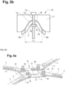
- figure 3a And 3b an actuator 10 configured to deform the connecting element 7 so as to cause it to pass from an inactive configuration ( picture 3a ) to an active configuration ( figure 3b ).
- the connecting element 7 extends in a first plane P1 and is deformable in a second plane P2, perpendicular to the first plane P1.
- the actuator 10 comprises a clamping support 11 on which the connecting element 7 bears.
- the clamping support 11 comprises a concavity 14 oriented towards the connecting element 7.
- the clamping support 11 comprises at the top of the concavity 14 an orifice 15.
- the connecting element comprises an orifice 16 located opposite the orifice 15 of the clamping support 11.
- the actuator further comprises a clamping screw 12 / nut 13 assembly, and the orifices 15, 16 of the clamping support 11 and of the connecting element 7 receive said clamping screw 12 / nut 13 assembly.
- the connecting element 7 When tightening the clamping screw 12 / nut 13 assembly, the connecting element 7 deforms by matching the shape of the concavity 14 of the clamping support 11, as illustrated in figure 3b . This leads to a shortening of the distance between the first 9a and second 9b attachment points of the connecting element and thus a tensioning of the tie rods 3.
- the actuator 10 is removable in this example, that is to say it serves to deform the connecting element 7 so as to bring it from the inactive to active configuration and then can be separated from the connecting element. bond 7 after deformation.
- the connecting element 7 extends in a first plane P1 and is deformable in a second plane P2, perpendicular to the first plane P1.
- Each tie rod 3 of the pair of tie rods 3 extends in the same plane as the connecting element 7 or in a parallel plane.
- the system 1 comprises two pairs of tie rods 3, each tie rod 3 having a first end 4 (not shown) fixed to the structure 2 and a second end 5 fixed to the connecting element 7.
- the actuator 10 is not removable. It is fixed both to the tie rods 3 and to the connecting element 7.
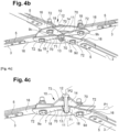
- THE figures 4a to 4c illustrate the device 6 for tensioning the tie rods 3 with the connecting element 7 in its inactive configuration (ie before deformation) and the 4d figure illustrates the device 6 with the connecting element 7 in its active configuration (ie after deformation).
- the tie rods 3 of each pair of tie rods 3 are arranged in a star around the connecting element 7.
- Each pair of tie rods 3 has two tie rods 3 aligned.
- the angle ⁇ between two adjacent tie rods is greater than or equal to 40° and less than or equal to 140°.
- each tie rod 3 is extended by a plate 16 on which the tie rod 3 is fixed by riveting.
- the plate 16 is for its part fixed to the times to the clamping support 11 and to the connecting element 7 by a screw/nut system.
- the use of such a plate 16 making it possible to connect the second end 5 of a tie rod 3 both to the clamping support 11 and to the connecting element 7 is optional. Indeed, it is possible to fix the second end 5 of each tie rod 3 directly to the clamping support 11 and to the connecting element 7.
- the clamping support 11 is sandwiched between the tie rods 3 and the connecting element 7.
- the clamping support 11 is in the form of a plate comprising in its center 73 a concavity 14 oriented towards the connecting element 7.
- the concavity 14 can have a parabolic, hyperbolic or even elliptical shape.
- the clamping support 11 has orifices allowing it to be fixed to the plates 16 and to the connecting element by the screw/nut system. These orifices are oblong in shape so as to allow the movement of the tie rods towards the center 73 of the clamping support 11.
- the connecting element 7 comprises two pairs of arms 18.
- the arms 18 are arranged in a star around the center 71 of the connecting element 7.
- Each arm 18 of the connecting element 7 is fixed to the second end 5 of a tie rod 3.
- Each arm 18 extends along the longitudinal axis of the tie rod 3 to which it is fixed or along an axis which extends with a slight deviation, for example of the order of plus or minus 10°, with respect to the axis longitudinal of the tie rod 3 to which it is fixed.
- each arm 18 extends along the longitudinal axis of the tie rod 3 to which it is fixed.
- each pair of arms 18 of the connecting element 7 extends along a longitudinal axis 80, 90.
- the axes longitudinal 80, 90 are in the plane P1 in which the connecting element 7 extends.
- the connecting element 7 is deformed along a longitudinal axis 100 which is perpendicular to the axes 80, 90.
- the structure 20 comprises at least two adjacent crosspieces 22, 32 comprising between them the stiffening system 1 according to the invention, that is to say at least two adjacent crosspieces 22, 32 between which the tie rods are tensioned at the using the tensioning device 6 according to the invention.
- the structure 20 forms between two adjacent crosspieces a rectangle 24, 34.
- the rectangle 24, 34 may comprise two opposite sides corresponding to two adjacent crosspieces 22, 32 and two opposite sides corresponding to the portions of beams 21 extending between said crosspieces 22, 32 adjacent.
- the tie rods 3, 23 connecting two adjacent crosspieces 22, 32 extend in the direction of the diagonals of the rectangle 24, 34.
- the structure 20 thus comprises a plurality of rectangles 24, 34 distributed along the main direction of extension, each rectangle 24, 34 comprising tie rods 3, 23 which extend along the diagonals of the rectangle 24, 34.
- the structure comprises crosspieces 22 which are movable in translation in both directions along the main direction of extension and crosspieces 32 which are fixed.
- the movable crosspieces 22 are fixed to the beams 21 by fixing systems such as, for example, screw/nut systems 30 received in oblong holes 40 provided in the beams 21.
- fixing systems such as, for example, screw/nut systems 30 received in oblong holes 40 provided in the beams 21.
- the tightening of the screw / nut systems 30 is such that it allows the movement in translation of the movable crosspieces 22 along the main direction of extension relative to the beams 21.
- the fixed crosspieces 32 are fixed to the beams 21 by fastening systems such as, for example, screw/nut systems 30 received in circular holes 50 made in the beams 21. These circular holes 50 do not allow the mobility of the crosspieces 32 by relative to the spars 21.
- the lattice structure 20 can be supported by at least two support arches 60.
- the lattice structure 20, and in particular the beams 21 of the lattice structure 20, are fixed to the ends of the support arches 60.
- the lattice structure 20 comprises fixed crosspieces 32 at its ends and at the level of the zone for attaching the hoops.
- the lattice structure comprises at least four fixed crosspieces 32.
- the lattice structure 20 comprises between two adjacent fixed crosspieces 32, at least one rectangle 24 in which the tie rods 3 are tensioned using the tensioning device 6 according to the invention, preferably centered with respect to the two fixed crosspieces 32 adjacent.
- the tensioning of the tie rods of the rectangles 24 in which the tie rods 3 are tensioned using the tensioning device 6 according to the invention makes it possible to drive the movable crosspieces 22 in translation along the main direction of extension and thus makes it possible to stiffen the whole of the lattice structure 20 .
- the entire lattice structure 20 is stiffened. It is then possible to tighten the screw/nut systems 30 received in the oblong holes 40 provided in the side members 21 so as to block the movement in translation of the movable crosspieces 22 along the main direction of extension relative to the side members 21.
Landscapes
- Engineering & Computer Science (AREA)
- General Engineering & Computer Science (AREA)
- Mechanical Engineering (AREA)
- Physics & Mathematics (AREA)
- Life Sciences & Earth Sciences (AREA)
- Sustainable Development (AREA)
- Architecture (AREA)
- Combustion & Propulsion (AREA)
- Sustainable Energy (AREA)
- Thermal Sciences (AREA)
- Chemical & Material Sciences (AREA)
- General Physics & Mathematics (AREA)
- Civil Engineering (AREA)
- Spectroscopy & Molecular Physics (AREA)
- Structural Engineering (AREA)
- Automation & Control Theory (AREA)
- Clamps And Clips (AREA)
- Bridges Or Land Bridges (AREA)
- Buildings Adapted To Withstand Abnormal External Influences (AREA)
- Prostheses (AREA)
- Surgical Instruments (AREA)
- Chemical Or Physical Treatment Of Fibers (AREA)
- Transition And Organic Metals Composition Catalysts For Addition Polymerization (AREA)
- Ceramic Products (AREA)
- Laminated Bodies (AREA)
- Superconductors And Manufacturing Methods Therefor (AREA)
- Signal Processing For Digital Recording And Reproducing (AREA)
Applications Claiming Priority (1)
| Application Number | Priority Date | Filing Date | Title |
|---|---|---|---|
| FR2112112A FR3129169B1 (fr) | 2021-11-16 | 2021-11-16 | Système de rigidification d’une structure |
Publications (1)
| Publication Number | Publication Date |
|---|---|
| EP4180741A1 true EP4180741A1 (de) | 2023-05-17 |
Family
ID=80735684
Family Applications (1)
| Application Number | Title | Priority Date | Filing Date |
|---|---|---|---|
| EP22207227.4A Withdrawn EP4180741A1 (de) | 2021-11-16 | 2022-11-14 | System zur versteifung einer struktur |
Country Status (7)
| Country | Link |
|---|---|
| US (1) | US11892348B2 (de) |
| EP (1) | EP4180741A1 (de) |
| CN (1) | CN116136341A (de) |
| AU (1) | AU2022268322A1 (de) |
| CA (1) | CA3182427A1 (de) |
| CL (1) | CL2022003188A1 (de) |
| FR (1) | FR3129169B1 (de) |
Citations (3)
| Publication number | Priority date | Publication date | Assignee | Title |
|---|---|---|---|---|
| WO2014088369A1 (ko) * | 2012-12-06 | 2014-06-12 | 조선대학교산학협력단 | 턴버클 |
| WO2018033495A1 (fr) | 2016-08-17 | 2018-02-22 | Venga Research Pte Ltd | Suiveur solaire |
| WO2021009425A1 (fr) | 2019-07-15 | 2021-01-21 | Nexans | Tirant pour structure notamment en treillis |
Family Cites Families (1)
| Publication number | Priority date | Publication date | Assignee | Title |
|---|---|---|---|---|
| US8844213B2 (en) * | 2008-04-08 | 2014-09-30 | Frank Posnansky | Device for generating solar power |
-
2021
- 2021-11-16 FR FR2112112A patent/FR3129169B1/fr not_active Expired - Fee Related
-
2022
- 2022-11-09 AU AU2022268322A patent/AU2022268322A1/en active Pending
- 2022-11-14 CA CA3182427A patent/CA3182427A1/fr active Pending
- 2022-11-14 US US17/986,662 patent/US11892348B2/en active Active
- 2022-11-14 EP EP22207227.4A patent/EP4180741A1/de not_active Withdrawn
- 2022-11-15 CN CN202211428979.3A patent/CN116136341A/zh active Pending
- 2022-11-15 CL CL2022003188A patent/CL2022003188A1/es unknown
Patent Citations (3)
| Publication number | Priority date | Publication date | Assignee | Title |
|---|---|---|---|---|
| WO2014088369A1 (ko) * | 2012-12-06 | 2014-06-12 | 조선대학교산학협력단 | 턴버클 |
| WO2018033495A1 (fr) | 2016-08-17 | 2018-02-22 | Venga Research Pte Ltd | Suiveur solaire |
| WO2021009425A1 (fr) | 2019-07-15 | 2021-01-21 | Nexans | Tirant pour structure notamment en treillis |
Also Published As
| Publication number | Publication date |
|---|---|
| CA3182427A1 (fr) | 2023-05-16 |
| US11892348B2 (en) | 2024-02-06 |
| CN116136341A (zh) | 2023-05-19 |
| US20230184584A1 (en) | 2023-06-15 |
| FR3129169A1 (fr) | 2023-05-19 |
| AU2022268322A1 (en) | 2023-06-01 |
| FR3129169B1 (fr) | 2024-02-09 |
| CL2022003188A1 (es) | 2023-02-03 |
Similar Documents
| Publication | Publication Date | Title |
|---|---|---|
| EP2388829A1 (de) | Tragestrukturmodul für Fotovoltaikpaneele, Tragestruktur, die solche Module umfasst, und Montageverfahren einer solchen Struktur | |
| WO1986002822A1 (fr) | Appareillage pour la stabilisation des fractures osseuses | |
| EP2814640B1 (de) | Werkzeug zum montieren einer aufhängungs-blattfeder an den fahrzeugrahmen und den radträger einer fahrzeugachse eines kraftfahrzeugs und zu dessen demontage | |
| EP0362049B1 (de) | System zum Verbinden zweier flacher Bauteile und seine Verwendung zum Zusammenbau von Stützelementen eines orthopädischen Korsetts | |
| EP3542203B1 (de) | Reflektor mit verbessertem design und dessen herstellungsverfahren für das gebiet der sonnenenergie | |
| EP4180741A1 (de) | System zur versteifung einer struktur | |
| EP2767499B1 (de) | Laschenverbindungsvorrichtung zur Verbindung von zwei Mastelementen, und Anordnung, die zwei Mastelemente und solche Laschenverbindungsvorrichtungen umfasst | |
| CA2982070A1 (fr) | Faisceau torsible pour pale, un ensemble de faisceaux torsibles, un rotor et un aeronef | |
| EP3999789B1 (de) | Zuganker, insbesondere für eine gitterstruktur | |
| FR2946712A1 (fr) | Bielle pour la construction aeronautique et procede de fabrication d'une telle bielle | |
| FR3004067A1 (fr) | Profile, notamment metallique, destine a permettre une fixation d'un film sur une structure de serre et systeme de fixation d'un film sur une structure de serre comprenant un tel profile | |
| EP1988195B1 (de) | Verbindungsstange für Zugsystem und Webrahmen, der eine solche Verbindungsstange umfasst | |
| FR2527254A1 (fr) | Procede et dispositif pour l'assemblage et l'alignement de panneaux de coffrage | |
| EP4133590B1 (de) | Gitterförmiger trägerbalken und sonnenfolger mit einem solchen träger | |
| FR2521624A3 (fr) | Raccord pour surfaces de cloture en treillis | |
| FR3036124A1 (fr) | Dispositif et procede de renforcement d'une poutre | |
| EP2239178A1 (de) | Dreieckiger Bremsbalken | |
| EP2466036B1 (de) | Verfahren zur Verstärkung eines Bauwerks mit Hilfe von Verstärkungsbändern | |
| FR2991113A1 (fr) | Ensemble de dispositifs et procede pour la fixation de torons electriques dans un aeronef | |
| FR2655679A1 (fr) | Dispositif d'assemblage de panneaux de coffrage. | |
| FR3043151A1 (fr) | Systeme de liaison bout a bout entre deux poutres et son application aux installations solaires lineaires | |
| FR3044687A1 (fr) | Procede de renforcement d'un element de construction par assemblage de modules de renfort et d'au moins une plaque connectee aux modules de renfort | |
| FR2547339A1 (fr) | Support a courbure ajustable pour coffrages d'ouvrages de maconnerie bombes | |
| EP1972730B1 (de) | Metalldrahtverbindung und ihr Herstellungsverfahren | |
| EP4308770A1 (de) | Befestigungselement zur anordnung eines gerüsts mit entlang pseudogeodesischer kurven gekrümmten profilelementen |
Legal Events
| Date | Code | Title | Description |
|---|---|---|---|
| PUAI | Public reference made under article 153(3) epc to a published international application that has entered the european phase |
Free format text: ORIGINAL CODE: 0009012 |
|
| STAA | Information on the status of an ep patent application or granted ep patent |
Free format text: STATUS: THE APPLICATION HAS BEEN PUBLISHED |
|
| AK | Designated contracting states |
Kind code of ref document: A1 Designated state(s): AL AT BE BG CH CY CZ DE DK EE ES FI FR GB GR HR HU IE IS IT LI LT LU LV MC ME MK MT NL NO PL PT RO RS SE SI SK SM TR |
|
| STAA | Information on the status of an ep patent application or granted ep patent |
Free format text: STATUS: REQUEST FOR EXAMINATION WAS MADE |
|
| 17P | Request for examination filed |
Effective date: 20231117 |
|
| RBV | Designated contracting states (corrected) |
Designated state(s): AL AT BE BG CH CY CZ DE DK EE ES FI FR GB GR HR HU IE IS IT LI LT LU LV MC ME MK MT NL NO PL PT RO RS SE SI SK SM TR |
|
| GRAP | Despatch of communication of intention to grant a patent |
Free format text: ORIGINAL CODE: EPIDOSNIGR1 |
|
| STAA | Information on the status of an ep patent application or granted ep patent |
Free format text: STATUS: GRANT OF PATENT IS INTENDED |
|
| INTG | Intention to grant announced |
Effective date: 20250102 |
|
| STAA | Information on the status of an ep patent application or granted ep patent |
Free format text: STATUS: THE APPLICATION IS DEEMED TO BE WITHDRAWN |
|
| 18D | Application deemed to be withdrawn |
Effective date: 20250503 |