EP4182192B1 - Dispositif de freinage électromécanique - Google Patents
Dispositif de freinage électromécanique Download PDFInfo
- Publication number
- EP4182192B1 EP4182192B1 EP21743044.6A EP21743044A EP4182192B1 EP 4182192 B1 EP4182192 B1 EP 4182192B1 EP 21743044 A EP21743044 A EP 21743044A EP 4182192 B1 EP4182192 B1 EP 4182192B1
- Authority
- EP
- European Patent Office
- Prior art keywords
- pressure
- pressure sleeve
- fluid
- brake device
- sleeve
- Prior art date
- Legal status (The legal status is an assumption and is not a legal conclusion. Google has not performed a legal analysis and makes no representation as to the accuracy of the status listed.)
- Active
Links
Images


Classifications
-
- B—PERFORMING OPERATIONS; TRANSPORTING
- B60—VEHICLES IN GENERAL
- B60T—VEHICLE BRAKE CONTROL SYSTEMS OR PARTS THEREOF; BRAKE CONTROL SYSTEMS OR PARTS THEREOF, IN GENERAL; ARRANGEMENT OF BRAKING ELEMENTS ON VEHICLES IN GENERAL; PORTABLE DEVICES FOR PREVENTING UNWANTED MOVEMENT OF VEHICLES; VEHICLE MODIFICATIONS TO FACILITATE COOLING OF BRAKES
- B60T7/00—Brake-action initiating means
- B60T7/02—Brake-action initiating means for personal initiation
- B60T7/08—Brake-action initiating means for personal initiation hand actuated
- B60T7/10—Disposition of hand control
- B60T7/107—Disposition of hand control with electrical power assistance
-
- B—PERFORMING OPERATIONS; TRANSPORTING
- B60—VEHICLES IN GENERAL
- B60T—VEHICLE BRAKE CONTROL SYSTEMS OR PARTS THEREOF; BRAKE CONTROL SYSTEMS OR PARTS THEREOF, IN GENERAL; ARRANGEMENT OF BRAKING ELEMENTS ON VEHICLES IN GENERAL; PORTABLE DEVICES FOR PREVENTING UNWANTED MOVEMENT OF VEHICLES; VEHICLE MODIFICATIONS TO FACILITATE COOLING OF BRAKES
- B60T13/00—Transmitting braking action from initiating means to ultimate brake actuator with power assistance or drive; Brake systems incorporating such transmitting means, e.g. air-pressure brake systems
- B60T13/10—Transmitting braking action from initiating means to ultimate brake actuator with power assistance or drive; Brake systems incorporating such transmitting means, e.g. air-pressure brake systems with fluid assistance, drive, or release
- B60T13/66—Electrical control in fluid-pressure brake systems
- B60T13/662—Electrical control in fluid-pressure brake systems characterised by specified functions of the control system components
-
- B—PERFORMING OPERATIONS; TRANSPORTING
- B60—VEHICLES IN GENERAL
- B60T—VEHICLE BRAKE CONTROL SYSTEMS OR PARTS THEREOF; BRAKE CONTROL SYSTEMS OR PARTS THEREOF, IN GENERAL; ARRANGEMENT OF BRAKING ELEMENTS ON VEHICLES IN GENERAL; PORTABLE DEVICES FOR PREVENTING UNWANTED MOVEMENT OF VEHICLES; VEHICLE MODIFICATIONS TO FACILITATE COOLING OF BRAKES
- B60T13/00—Transmitting braking action from initiating means to ultimate brake actuator with power assistance or drive; Brake systems incorporating such transmitting means, e.g. air-pressure brake systems
- B60T13/74—Transmitting braking action from initiating means to ultimate brake actuator with power assistance or drive; Brake systems incorporating such transmitting means, e.g. air-pressure brake systems with electrical assistance or drive
- B60T13/741—Transmitting braking action from initiating means to ultimate brake actuator with power assistance or drive; Brake systems incorporating such transmitting means, e.g. air-pressure brake systems with electrical assistance or drive acting on an ultimate actuator
-
- B—PERFORMING OPERATIONS; TRANSPORTING
- B60—VEHICLES IN GENERAL
- B60T—VEHICLE BRAKE CONTROL SYSTEMS OR PARTS THEREOF; BRAKE CONTROL SYSTEMS OR PARTS THEREOF, IN GENERAL; ARRANGEMENT OF BRAKING ELEMENTS ON VEHICLES IN GENERAL; PORTABLE DEVICES FOR PREVENTING UNWANTED MOVEMENT OF VEHICLES; VEHICLE MODIFICATIONS TO FACILITATE COOLING OF BRAKES
- B60T17/00—Component parts, details, or accessories of power brake systems not covered by groups B60T8/00, B60T13/00 or B60T15/00, or presenting other characteristic features
- B60T17/08—Brake cylinders other than ultimate actuators
- B60T17/16—Locking of brake cylinders
-
- B—PERFORMING OPERATIONS; TRANSPORTING
- B60—VEHICLES IN GENERAL
- B60T—VEHICLE BRAKE CONTROL SYSTEMS OR PARTS THEREOF; BRAKE CONTROL SYSTEMS OR PARTS THEREOF, IN GENERAL; ARRANGEMENT OF BRAKING ELEMENTS ON VEHICLES IN GENERAL; PORTABLE DEVICES FOR PREVENTING UNWANTED MOVEMENT OF VEHICLES; VEHICLE MODIFICATIONS TO FACILITATE COOLING OF BRAKES
- B60T17/00—Component parts, details, or accessories of power brake systems not covered by groups B60T8/00, B60T13/00 or B60T15/00, or presenting other characteristic features
- B60T17/18—Safety devices; Monitoring
- B60T17/22—Devices for monitoring or checking brake systems; Signal devices
-
- B—PERFORMING OPERATIONS; TRANSPORTING
- B60—VEHICLES IN GENERAL
- B60T—VEHICLE BRAKE CONTROL SYSTEMS OR PARTS THEREOF; BRAKE CONTROL SYSTEMS OR PARTS THEREOF, IN GENERAL; ARRANGEMENT OF BRAKING ELEMENTS ON VEHICLES IN GENERAL; PORTABLE DEVICES FOR PREVENTING UNWANTED MOVEMENT OF VEHICLES; VEHICLE MODIFICATIONS TO FACILITATE COOLING OF BRAKES
- B60T8/00—Arrangements for adjusting wheel-braking force to meet varying vehicular or ground-surface conditions, e.g. limiting or varying distribution of braking force
- B60T8/32—Arrangements for adjusting wheel-braking force to meet varying vehicular or ground-surface conditions, e.g. limiting or varying distribution of braking force responsive to a speed condition, e.g. acceleration or deceleration
-
- F—MECHANICAL ENGINEERING; LIGHTING; HEATING; WEAPONS; BLASTING
- F16—ENGINEERING ELEMENTS AND UNITS; GENERAL MEASURES FOR PRODUCING AND MAINTAINING EFFECTIVE FUNCTIONING OF MACHINES OR INSTALLATIONS; THERMAL INSULATION IN GENERAL
- F16D—COUPLINGS FOR TRANSMITTING ROTATION; CLUTCHES; BRAKES
- F16D55/00—Brakes with substantially-radial braking surfaces pressed together in axial direction, e.g. disc brakes
- F16D55/02—Brakes with substantially-radial braking surfaces pressed together in axial direction, e.g. disc brakes with axially-movable discs or pads pressed against axially-located rotating members
- F16D55/22—Brakes with substantially-radial braking surfaces pressed together in axial direction, e.g. disc brakes with axially-movable discs or pads pressed against axially-located rotating members by clamping an axially-located rotating disc between movable braking members, e.g. movable brake discs or brake pads
- F16D55/224—Brakes with substantially-radial braking surfaces pressed together in axial direction, e.g. disc brakes with axially-movable discs or pads pressed against axially-located rotating members by clamping an axially-located rotating disc between movable braking members, e.g. movable brake discs or brake pads with a common actuating member for the braking members
- F16D55/225—Brakes with substantially-radial braking surfaces pressed together in axial direction, e.g. disc brakes with axially-movable discs or pads pressed against axially-located rotating members by clamping an axially-located rotating disc between movable braking members, e.g. movable brake discs or brake pads with a common actuating member for the braking members the braking members being brake pads
- F16D55/226—Brakes with substantially-radial braking surfaces pressed together in axial direction, e.g. disc brakes with axially-movable discs or pads pressed against axially-located rotating members by clamping an axially-located rotating disc between movable braking members, e.g. movable brake discs or brake pads with a common actuating member for the braking members the braking members being brake pads in which the common actuating member is moved axially, e.g. floating caliper disc brakes
-
- F—MECHANICAL ENGINEERING; LIGHTING; HEATING; WEAPONS; BLASTING
- F16—ENGINEERING ELEMENTS AND UNITS; GENERAL MEASURES FOR PRODUCING AND MAINTAINING EFFECTIVE FUNCTIONING OF MACHINES OR INSTALLATIONS; THERMAL INSULATION IN GENERAL
- F16D—COUPLINGS FOR TRANSMITTING ROTATION; CLUTCHES; BRAKES
- F16D65/00—Parts or details
- F16D65/14—Actuating mechanisms for brakes; Means for initiating operation at a predetermined position
- F16D65/16—Actuating mechanisms for brakes; Means for initiating operation at a predetermined position arranged in or on the brake
- F16D65/18—Actuating mechanisms for brakes; Means for initiating operation at a predetermined position arranged in or on the brake adapted for drawing members together, e.g. for disc brakes
- F16D65/183—Actuating mechanisms for brakes; Means for initiating operation at a predetermined position arranged in or on the brake adapted for drawing members together, e.g. for disc brakes with force-transmitting members arranged side by side acting on a spot type force-applying member
-
- F—MECHANICAL ENGINEERING; LIGHTING; HEATING; WEAPONS; BLASTING
- F16—ENGINEERING ELEMENTS AND UNITS; GENERAL MEASURES FOR PRODUCING AND MAINTAINING EFFECTIVE FUNCTIONING OF MACHINES OR INSTALLATIONS; THERMAL INSULATION IN GENERAL
- F16D—COUPLINGS FOR TRANSMITTING ROTATION; CLUTCHES; BRAKES
- F16D66/00—Arrangements for monitoring working conditions, e.g. wear, temperature
-
- B—PERFORMING OPERATIONS; TRANSPORTING
- B60—VEHICLES IN GENERAL
- B60T—VEHICLE BRAKE CONTROL SYSTEMS OR PARTS THEREOF; BRAKE CONTROL SYSTEMS OR PARTS THEREOF, IN GENERAL; ARRANGEMENT OF BRAKING ELEMENTS ON VEHICLES IN GENERAL; PORTABLE DEVICES FOR PREVENTING UNWANTED MOVEMENT OF VEHICLES; VEHICLE MODIFICATIONS TO FACILITATE COOLING OF BRAKES
- B60T7/00—Brake-action initiating means
- B60T7/12—Brake-action initiating means for automatic initiation; for initiation not subject to will of driver or passenger
- B60T7/122—Brake-action initiating means for automatic initiation; for initiation not subject to will of driver or passenger for locking of reverse movement
-
- F—MECHANICAL ENGINEERING; LIGHTING; HEATING; WEAPONS; BLASTING
- F16—ENGINEERING ELEMENTS AND UNITS; GENERAL MEASURES FOR PRODUCING AND MAINTAINING EFFECTIVE FUNCTIONING OF MACHINES OR INSTALLATIONS; THERMAL INSULATION IN GENERAL
- F16D—COUPLINGS FOR TRANSMITTING ROTATION; CLUTCHES; BRAKES
- F16D2121/00—Type of actuator operation force
- F16D2121/02—Fluid pressure
- F16D2121/04—Fluid pressure acting on a piston-type actuator, e.g. for liquid pressure
-
- F—MECHANICAL ENGINEERING; LIGHTING; HEATING; WEAPONS; BLASTING
- F16—ENGINEERING ELEMENTS AND UNITS; GENERAL MEASURES FOR PRODUCING AND MAINTAINING EFFECTIVE FUNCTIONING OF MACHINES OR INSTALLATIONS; THERMAL INSULATION IN GENERAL
- F16D—COUPLINGS FOR TRANSMITTING ROTATION; CLUTCHES; BRAKES
- F16D2121/00—Type of actuator operation force
- F16D2121/18—Electric or magnetic
- F16D2121/24—Electric or magnetic using motors
-
- F—MECHANICAL ENGINEERING; LIGHTING; HEATING; WEAPONS; BLASTING
- F16—ENGINEERING ELEMENTS AND UNITS; GENERAL MEASURES FOR PRODUCING AND MAINTAINING EFFECTIVE FUNCTIONING OF MACHINES OR INSTALLATIONS; THERMAL INSULATION IN GENERAL
- F16D—COUPLINGS FOR TRANSMITTING ROTATION; CLUTCHES; BRAKES
- F16D2125/00—Components of actuators
- F16D2125/18—Mechanical mechanisms
- F16D2125/20—Mechanical mechanisms converting rotation to linear movement or vice versa
- F16D2125/34—Mechanical mechanisms converting rotation to linear movement or vice versa acting in the direction of the axis of rotation
- F16D2125/40—Screw-and-nut
Definitions
- the invention relates to an electromechanical braking device according to the preamble of claim 1.
- Such braking devices are known in the state of the art. Unlike a classic hydraulic brake, in an electromechanical braking device, brake pads are subjected to a force in the direction of the respective friction partner by means of an electromechanical tensioning device in order to generate the desired deceleration torque.
- a classic hydraulic braking device is shown in the document WO 2005/073043 A1
- an electrically controlled parking brake system is proposed which is designed to generate and maintain braking forces.
- a first approach is to monitor the operating parameters of the electromechanical drive and to determine the currently applied clamping force from the variables thus determined, in particular the motor current and the motor position. Such an approach is used, for example, in the EP 1 141 686 B1 the applicant.
- a second well-known approach is to measure the forces acting in a brake calliper or actuating mechanism using appropriate force sensors and thus to determine the current clamping force.
- the DE 196 40 995 C2 the applicant that the clamping force exerted can be deduced from a deformation of the clamping device or of an arm which supports the clamping force.
- the present invention is concerned with the task of providing an alternative concept for determining the application force in an electromechanical braking device, which is characterized in particular by improved accuracy using inexpensive technology.
- the invention relates to an electromechanical braking device with a brake caliper and a pressure piston movably mounted in the brake caliper along an application direction, wherein the braking device has an electromechanical tensioning device, wherein the tensioning device is supported on the pressure piston on the one hand and is designed to apply a force to the pressure piston acting along the application direction.
- the braking device has at least one hydraulically closed, fluid-filled cavity, wherein the tensioning device is supported indirectly on the brake caliper via the fluid-filled cavity on the other hand, and wherein a pressure sensor is hydraulically connected to the fluid-filled cavity and is designed to determine the fluid pressure within the fluid-filled cavity.
- the invention is based on the idea of using the known determination of the clamping force from a hydraulic pressure for hydraulic brake devices for the determination of the clamping force of a electromechanical braking device.
- This is achieved according to the invention in that, by supporting the clamping device on a fluid-filled cavity, the clamping force acting on the pressure piston of the braking device also acts on the fluid-filled cavity and thereby leads to an increase in pressure within the fluid.
- the fluid-filled cavity therefore acts like a hydraulic pressure cushion.
- the clamping force acting can then be determined from the fluid pressure, with knowledge of the geometry of the corresponding elements, i.e. the cavity and the pressure sensor.
- the clamping force determined in this way can then in turn be fed to a control unit of the braking device to control a corresponding clamping force regulator.
- the fluid used for the cavity is preferably an environmentally friendly liquid that is hydraulically viscous over the entire relevant temperature range.
- the "application direction” is understood to mean the direction of movement of the pressure piston which causes the brake pads arranged on the pressure piston to engage with the corresponding friction partners.
- the term "pressure piston” should not be understood to be restrictive with regard to the geometric shape of the corresponding element.
- a pressure piston in the sense of the present invention is not necessarily piston-shaped. Rather, a pressure piston is always to be understood to be the element which is moved from a rest position when the brake device is actuated, whereby As a result of the displacement, the friction partners of the braking devices are brought into engagement.
- the clamping device has an electric motor-driven threaded spindle and a spindle nut, whereby the spindle nut is supported on the pressure piston in the application direction and whereby the threaded spindle is supported on the brake caliper via the fluid-filled cavity against the application direction.
- the spindle nut and thus the pressure piston are displaced along the application direction by rotation of the threaded spindle, or are subjected to a force along the application direction.
- the reaction force generated when the pressure piston is subjected to an application force is completely represented as fluid pressure due to the support of the threaded spindle on the fluid-filled cavity. This makes it possible to determine the clamping force precisely from the pressure measured in the fluid-filled cavity.
- the spindle drive described is preferably designed as a low-friction ball screw drive.
- the spindle nut is arranged at least partially in a recess within the pressure piston
- the spindle nut can also be arranged completely within the pressure piston, so that the force can be transmitted from the spindle nut to the pressure piston with as little play and as safe as possible.
- the threaded spindle also extends through the pressure piston in sections.
- a recess for the threaded spindle is preferably formed behind the spindle nut in the clamping direction, with the depth of the recess determining the maximum displacement path of the spindle nut.
- the threaded spindle has a first longitudinal section with a first diameter and a second longitudinal section adjacent to the first longitudinal section, wherein an external thread is formed in the second longitudinal section, the diameter of which is larger than the first diameter.
- a support ring is arranged on the first longitudinal section of the threaded spindle, wherein the inner diameter of the support ring is smaller than the outer diameter of the second longitudinal section of the threaded spindle, so that the threaded spindle is supported indirectly on the brake caliper via the support ring against the application direction via the fluid-filled cavity.
- the diameter of the first longitudinal section of the threaded spindle and, accordingly, the inner diameter of the support ring is smaller than the core diameter of the threaded spindle.
- the support is not provided on the thread itself, but on the core area of the spindle, which is usually more stable. This can prevent damage to the thread in particular when high forces are applied.
- the inventive concept for determining the clamping force is based on the fact that the force exerted by the clamping device on the pressure piston in a fluid-filled cavity due to a Supporting the clamping device on the cavity causes an increase in pressure in the fluid contained therein.
- the cavity is designed in such a way that the volume of the cavity can be easily changed when a force is applied, particularly along the clamping direction, i.e. with as little mechanical resistance as possible. In this case, a reduction in the pressure generated is reduced because part of the force applied has to be used to deform the cavity, and the measurement accuracy is therefore improved.
- such easy deformability of the cavity is ensured by the fluid-filled cavity being formed between a first and a second pressure sleeve, the first pressure sleeve being supported on the brake caliper against the application direction, while the second pressure sleeve is supported on the clamping device, in particular on the support ring, in the application direction.
- the pressure sleeves are preferably arranged in the brake device in such a way that they can move independently of one another along the application direction.
- the term "sleeve" is not to be understood as limiting the geometry of the corresponding element.
- the clamping device exerts a force on the pressure piston in the clamping direction, a corresponding reaction force acts simultaneously on the second pressure sleeve, which drives the second pressure sleeve in the direction of the first pressure sleeve and consequently leads to a compression of the cavity formed between the pressure sleeves. Since the cavity is in turn sealed fluid-tight, the clamping force exerted by the clamping device is represented in the form of a pressure within the cavity.
- the first pressure sleeve is attached to the brake calliper so that the first pressure sleeve cannot be moved relative to the brake calliper. This avoids the first pressure sleeve having to be moved so far against the application direction at the start of an application process that it comes into contact with a part of the brake caliper in such a way that further displacement against the application direction is blocked. Such a displacement could lead to falsification of the measured pressure within the cavity and thus to an incorrect determination of the application force from the measured pressure.
- first pressure sleeve and the second pressure sleeve each have an opening, with the clamping device extending through the opening.
- the threaded spindle in particular extends through the central opening.
- the respective opening in the pressure sleeves is preferably centered.
- the second pressure sleeve is mounted in the first pressure sleeve so that it can move along the application direction.
- the first pressure sleeve is particularly preferably fixed to the brake caliper.
- the second pressure sleeve is then preferably mounted in the first pressure sleeve such that the second pressure sleeve can only move along the application direction.
- the second pressure sleeve is slide-mounted on at least two bearing surfaces on the first pressure sleeve, wherein sealing elements are arranged in the area of the bearing surfaces on the first pressure sleeve and/or the second pressure sleeve, which seal the cavity formed between the pressure sleeves in a fluid-tight manner.
- the sealing elements are preferably sealing rings, which can be arranged, for example, in grooves formed in the first and/or the second pressure sleeve in the area of the bearing surfaces.
- a first of the sealing elements is fastened in or on the first pressure sleeve, while a second of the sealing elements is fastened in or on the second pressure sleeve.
- first and second pressure sleeves are each pot-shaped, with the clamping device being arranged at least in sections within the pot shape.
- the term "pot shape” is therefore to be understood as a particularly axially symmetrical geometry that is open on one side with a base surface and circumferential side walls that border the base surface radially on the outside.
- the extension of the pot shape in the radial direction can be larger or smaller than the extension of the pot shape in the axial direction.
- the pressure sensor is arranged in a side wall of the cup shape of the first pressure sleeve. In this way, the arrangement of the pressure sensor does not hinder the design of the clamping device itself, since the pressure sensor is arranged laterally offset next to an actuating axis of the clamping device.
- a further embodiment provides that the first pressure sleeve and the second pressure sleeve are each plate-shaped, with the pressure sleeves being connected to one another at their radial outer edges and at the edges of their respective openings via membranes, so that the cavity formed between the pressure sleeves is sealed fluid-tight by the membranes.
- a plate shape is understood to mean a concave disk shape whose extension in the axial direction is smaller than the extension in the radial direction.
- bellows can be used as membranes, which are arranged on a radial outer edge of the plate shape and, in the case of a centered opening within the plate shape, as described above, in the area of this opening.
- the design of the pressure sleeves as a plate shape has the advantage that the pressure sleeves and thus the arrangement to determine the clamping force is easily scalable, since the ring surfaces of the plate shapes can be easily adapted to the clamping forces occurring in the corresponding braking device.
- the membranes can be welded to the pressure sleeves, particularly at their contact points with the pressure sleeves.
- the pressure sensor is arranged in the plate shape of the first pressure sleeve between the membranes.
- a further embodiment provides that the pressure sensor is screwed into the first pressure sleeve.
- the pressure within the cavity determined by the pressure sensor can be transmitted to a tensioning force controller of the braking device by means of a preferably integrated interface.
- a control unit for the pressure sensor can also be integrated into the control system of the braking device.
- the Figure 1 shows a perspective view of an exemplary electromechanical braking device 100, which in the embodiment shown here is designed as a floating caliper brake.
- the braking device 100 has an electric motor 102, which is connected via a gear 104 to a tensioning device 106, which in the embodiment shown here is designed as a rotation-translation gear in the form of a spindle drive. This will be explained below with reference to the Figures 2 and 4 explained in more detail.
- the arrangement of electric motor 102, transmission 104 and tensioning device 106 is arranged on a brake caliper 108, which can be attached to the wheel suspension of a vehicle via a floating bearing in a brake caliper holder 168 with corresponding fastening points 110.
- a pressure piston 112 is arranged in the brake caliper 108 such that the pressure piston 112 can be moved along an application direction 114 by a corresponding control of the electric motor 102 and a resulting actuation of the tensioning device 106.
- a first friction lining 116 is arranged on the pressure piston 112, which is moved in the direction of a second friction lining 118 when the pressure piston 112 moves in the application direction 114.
- a brake disk that is firmly connected to the vehicle wheel is arranged between the friction linings 116 and 118, so that when the first friction lining 116 is sufficiently displaced in the application direction, the first friction lining 116 comes into contact with the brake disk.
- the tensioning device 106 is further actuated, the second friction lining 118 is moved against the application direction 114, i.e. in the direction of a gap between the friction linings 116 and 118 arranged brake disc until both friction pads 116 and 118 rest on the brake disc.
- the braking device 100 has at least one hydraulically closed, fluid-filled cavity, wherein the tensioning device 106 is supported not only on the pressure piston 112, but also indirectly on the brake caliper 108 via the fluid-filled cavity.
- a pressure sensor is hydraulically connected to the fluid-filled cavity and is designed to determine the fluid pressure within the fluid-filled cavity.
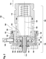
- the Figure 2 a sectional view of a partial area of a first exemplary braking device 100. For reasons of clarity, only the elements of the braking device 100 relevant to the design of the inventive approach are shown.
- the braking device 100 has a clamping device 106 which is designed to apply a force to the pressure piston 112 along a clamping direction 114.
- the clamping device 106 has a spindle drive which has a threaded spindle 116 and a spindle nut 166 arranged on the threaded spindle 116.
- the threaded spindle 116 is, as previously explained, connected via a gear 104 (not shown) to the electric motor 102 (also not shown) in such a way that the threaded spindle 116 is driven by a corresponding Control of the electric motor 102 can be set in rotation about its longitudinal axis 120.
- the spindle nut 166 is arranged partially within the pressure piston 112 and is supported on the pressure piston 112 in the application direction. Furthermore, the spindle nut 166 is secured against rotation about the longitudinal axis of the threaded spindle 116, so that a rotation of the threaded spindle 116 leads to a displacement of the spindle nut 166 and thus of the pressure piston 112 along the application direction 114.
- the spindle drive is preferably designed as a low-friction ball screw drive.
- the clamping device 106 is supported against the application direction on a fluid-filled cavity 122.
- the fluid-filled cavity 122 is formed between two pot-shaped pressure sleeves 124 and 126.
- a first of the pressure sleeves 124 is supported on the brake caliper 108 against the application direction 114.
- the second pressure sleeve 126 is mounted in the first pressure sleeve 124 so that it can move along the application direction 114.
- the first and second pressure sleeves 124 and 126 have bearing surfaces 128 and 130 on which the pressure sleeves 124 and 126 are slide-mounted so that they can move along the application direction 114.
- the cavity 122 formed between the pressure sleeves 124 and 126 is sealed in a fluid-tight manner by sealing elements 132 and 134 designed as sealing rings, wherein the sealing elements 132 and 134 are each arranged in corresponding grooves formed in the pressure sleeves 124 and 126.
- the sealing elements 132 and 134 are arranged in the area of the bearing surfaces 128 and 130 of the pressure sleeves 124 and 126 and together with the bearing surfaces 128 and 130 form plain bearings.
- the cup-shaped pressure sleeves 124 and 126 each have a base surface 136 and 138, as well as a circumferential side wall 140 and 142.
- a centered opening 144 is formed in the base surfaces 136 and 138 of the pressure sleeves 124 and 126, through which the threaded spindle 116 extends.
- the second pressure sleeve 126 has a extending counter to the clamping direction 114, which projects into the opening 144 of the first pressure sleeve 124 and on whose radial outer side the bearing surface 130 is formed.
- One of the plain bearings is thus formed with a sealing element 134 arranged in a groove of the first pressure sleeve 124.
- the second plain bearing is formed in the side walls 140 and 142 at their axial end regions in the clamping direction 114.
- a bearing surface is formed on the inner surface of the side wall 140 of the first pressure sleeve 124, on which a sealing element 132 can slide, which is arranged in a groove formed in the side wall 142 of the second pressure sleeve 126.
- a pressure sensor 148 is arranged in the side wall 140 of the first pressure sleeve 124, which is designed to measure the fluid pressure prevailing in the cavity 122.
- the cavity 122 is preferably filled with a hydraulic fluid.
- the representation of a single element as a pressure sensor 148 is not to be understood as limiting. Rather, in the arrangement shown, several pressure sensors 148 can also be hydraulically connected to the cavity 122, so that redundancy is created in determining the pressure prevailing in the cavity 122.
- the spindle nut 166 is arranged on the threaded spindle 116 in a rotationally fixed manner relative to the brake caliper 108 and axially displaceable along the threaded spindle 116, so that when the threaded spindle 116 rotates, the spindle nut 166 and thus the pressure piston 112 are displaced.
- a reaction force is generated that runs counter to the application direction 114 and acts on the threaded spindle 116.
- a support ring 150 is arranged on the threaded spindle 116, which is designed to absorb a force acting counter to the application direction 114 and is supported on the second pressure sleeve 126.
- An axial bearing 152 is formed between the support ring 150 and the second pressure sleeve 126 to absorb the resulting forces.
- the threaded spindle 116 has two longitudinal sections with different diameters.
- the diameter of the threaded spindle 116 is smaller in a first longitudinal section 154 than in a second longitudinal section 156, with the first longitudinal section 154 extending from the rear end of the threaded spindle 116, i.e. the end facing the gear.
- the external thread of the threaded spindle 116 is formed in the second longitudinal section 156, with the core diameter of the thread being larger than the diameter of the threaded spindle 116 in the first longitudinal section 154.
- the inner diameter of the support ring 150 is smaller than the core diameter of the second longitudinal section 156, but larger than the diameter of the first longitudinal section 154, so that the support ring 150 is supported in the clamping direction 114 at the transition between the longitudinal sections 154 and 156.
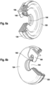
- the Figure 3 shows again the arrangement of the two pressure sleeves 124 and 126 without the clamping device arranged therein.
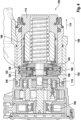
- the Figure 4 shows a sectional view of a second embodiment of a braking device 100 in accordance with the present invention.
- the braking device 100 shown here differs from the one previously described with reference to the Figures 2 and 3
- the brake device 100 described above differs essentially from the previously described brake device 100 by a different design of the pressure sleeves 124 and 126.
- the pressure sleeves 124 and 126 are plate-shaped, with the first pressure sleeve 124 in turn being supported on the brake caliper.
- the second pressure sleeve 126 is mounted on the first longitudinal section 154 of the threaded spindle 116 along the Actuation direction 114 is slidably mounted.
- the threaded spindle 116 is supported on the second pressure sleeve 126 via a support ring 150 against the clamping direction 114, so that a force acting on the pressure piston 112 is transmitted to the second pressure sleeve 126.
- a fluid-tight cavity 122 formed between the pressure sleeves 124 and 126 is subjected to a force such that the force is reflected in a corresponding change in the pressure prevailing in the cavity 122.
- the cavity 122 is, unlike in the previously described embodiment, limited by the pressure sleeves 124 and 126 on the one hand and by membranes 158 and 160 arranged on the edges of the pressure sleeves. This is shown in the Figure 5 presented again in detail.
- the pressure sleeves 124 and 126 each have centered openings 144 through which the threaded spindle 116 extends.
- the membranes 158 and 160 designed as bellows are arranged on the radial outer edges of the plate shape of the pressure sleeves, as well as on the edges of the centered opening 144.
- the membranes 158 and 160 are also preferably designed such that they allow a movement of the second pressure sleeve 126 in the direction of the first pressure sleeve 124 within narrow limits, but do not bulge radially outwards or inwards in the event of strong pressure changes within the cavity 122, so that a force acting on the cavity 122 is completely represented as a pressure change in the cavity 122.
- the pressure sensor 148 for detecting the pressure prevailing in the cavity 122 is arranged within the plate surface of the first pressure sleeve 124 between the membranes 158 and 160.
- the pressure sensor 148 can in particular be screwed into a corresponding recess 162 so that it can be easily replaced in the event of a defect, for example.
- FIG. 6 two further perspective views of the arrangement of the first and second pressure sleeves 124 and 126 with the Pressure sensor 148.
- the interface 164 of the pressure sensor 148 is shown, via which a determined pressure information can be transmitted to a controller of the braking device 100.
Landscapes
- Engineering & Computer Science (AREA)
- Mechanical Engineering (AREA)
- Transportation (AREA)
- General Engineering & Computer Science (AREA)
- Braking Arrangements (AREA)
Claims (15)
- Dispositif de freinage électromécanique (100) avec un étrier de frein (108) et un piston de pression (112) monté dans l'étrier de frein (108) de manière mobile le long d'une direction de serrage (114), le dispositif de freinage (100) présentant un dispositif de serrage électromécanique (106), le dispositif de serrage (106) s'appuyant d'une part sur le piston de pression (112) et étant réalisé pour solliciter le piston de pression (112) avec une force agissant le long de la direction de serrage (114),
caractérisé en ce que
le dispositif de freinage (100) présente au moins une cavité (122) fermée hydrauliquement, remplie de fluide, le dispositif de serrage (106) s'appuyant d'autre part indirectement sur l'étrier de frein (108) par l'intermédiaire de la cavité (122) remplie de fluide, et un capteur de pression (148) étant relié hydrauliquement à la cavité (122) remplie de fluide et étant réalisé pour déterminer la pression du fluide à l'intérieur de la cavité (122) remplie de fluide. - Dispositif de freinage électromécanique (100) selon la revendication 1, caractérisé en ce que le dispositif de serrage (106) présente une broche filetée (116) entraînée par un moteur électrique et un écrou de broche (166), l'écrou de broche (166) s'appuyant sur le piston de pression (112) dans la direction de serrage (114) et la broche filetée (116) s'appuyant sur l'étrier de frein (108) par l'intermédiaire de la cavité (122) remplie de fluide à l'encontre de la direction de serrage (114).
- Dispositif de freinage électromécanique (100) selon la revendication 2, caractérisé en ce que l'écrou de broche (166) est au moins partiellement agencé dans un évidement à l'intérieur du piston de pression (112).
- Dispositif de freinage électromécanique (100) selon la revendication 2 ou 3, caractérisé en ce que la broche filetée (116) présente une première section longitudinale (154) ayant un premier diamètre et une deuxième section longitudinale (156) adjacente à la première section longitudinale (154), un filetage extérieur étant réalisé dans la deuxième section longitudinale (156), le diamètre de ce filetage étant supérieur au premier diamètre.
- Dispositif de freinage électromécanique (100) selon la revendication 4, caractérisé en ce qu'une bague d'appui (150) est agencée sur la première section longitudinale (154) de la broche filetée (116), le diamètre intérieur de la bague d'appui (150) étant inférieur au diamètre extérieur de la deuxième section longitudinale (156) de la broche filetée (116), de telle sorte que la broche filetée (116) s'appuie indirectement sur l'étrier de frein (108) par l'intermédiaire de la bague d'appui (150), à l'encontre de la direction de serrage (114), par l'intermédiaire de la cavité (122) remplie de fluide.
- Dispositif de freinage électromécanique (100) selon l'une quelconque des revendications précédentes, caractérisé en ce que la cavité (122) remplie de fluide est réalisée entre un premier (124) et un deuxième manchon de pression (126), le premier manchon de pression (124) s'appuyant sur l'étrier de frein (108) à l'encontre de la direction de serrage (114), tandis que le deuxième manchon de pression (126) s'appuie sur le dispositif de serrage (106) dans la direction de serrage (114).
- Dispositif de freinage électromécanique (100) selon la revendication 6, caractérisé en ce que le premier manchon de pression (124) est fixé à l'étrier de frein (108).
- Dispositif de freinage électromécanique (100) selon l'une quelconque des revendications 6 ou 7, caractérisé en ce que le premier manchon de pression (124) et le deuxième manchon de pression (126) présentent chacun une ouverture (144), le dispositif de serrage (106) s'étendant à travers l'ouverture (144).
- Dispositif de freinage électromécanique (100) selon l'une quelconque des revendications 6 à 8, caractérisé en ce que le deuxième manchon de pression (126) est monté coulissant dans le premier manchon de pression (124) le long de la direction de serrage (114).
- Dispositif de freinage électromécanique (100) selon la revendication 9, caractérisé en ce que le deuxième manchon de pression (126) est monté à coulissement sur au moins deux surfaces de montage (128, 130) sur le premier manchon de pression (124), des éléments d'étanchéité (132, 134) étant agencés dans la zone des surfaces de montage (128, 130) sur le premier manchon de pression (124) et/ou le deuxième manchon de pression (126), lesquels assurent l'étanchéité aux fluides de la cavité (122) réalisée entre les manchons de pression (124, 126).
- Dispositif de freinage électromécanique (100) selon l'une quelconque des revendications 6 à 10, caractérisé en ce que le premier (124) et le deuxième (126) manchons de pression sont chacun réalisés sous forme de pot, le dispositif de serrage (106) étant agencé au moins par sections à l'intérieur de la forme de pot.
- Dispositif de freinage électromécanique (100) selon la revendication 11, caractérisé en ce que le capteur de pression (148) est agencé dans une paroi latérale (140) de la forme de pot du premier manchon de pression (124).
- Dispositif de freinage électromécanique (100) selon l'une quelconque des revendications 6 à 8, caractérisé en ce que le premier manchon de pression (124) et le deuxième manchon de pression (126) sont chacun en forme d'assiette, les manchons de pression (124, 126) étant reliés entre eux par l'intermédiaire de membranes (158, 160) sur leurs bords extérieurs radiaux et sur les bords de leurs ouvertures respectives (144), de telle sorte que la cavité (122) réalisée entre les manchons de pression (124, 126) est fermée de manière étanche aux fluides par les membranes (158, 160).
- Dispositif de freinage électromécanique (100) selon la revendication 13, caractérisé en ce que le capteur de pression (148) est agencé dans la forme d'assiette du premier manchon de pression (124) entre les membranes (158, 160).
- Dispositif de freinage électromécanique (100) selon l'une quelconque des revendications 6 à 14, caractérisé en ce que le capteur de pression (148) est vissé dans le premier manchon de pression (124).
Applications Claiming Priority (2)
| Application Number | Priority Date | Filing Date | Title |
|---|---|---|---|
| DE102020208769.5A DE102020208769A1 (de) | 2020-07-14 | 2020-07-14 | Elektromechanische Bremsvorrichtung |
| PCT/DE2021/200091 WO2022012722A1 (fr) | 2020-07-14 | 2021-07-08 | Dispositif de frein électromécanique |
Publications (2)
| Publication Number | Publication Date |
|---|---|
| EP4182192A1 EP4182192A1 (fr) | 2023-05-24 |
| EP4182192B1 true EP4182192B1 (fr) | 2025-01-29 |
Family
ID=76971590
Family Applications (1)
| Application Number | Title | Priority Date | Filing Date |
|---|---|---|---|
| EP21743044.6A Active EP4182192B1 (fr) | 2020-07-14 | 2021-07-08 | Dispositif de freinage électromécanique |
Country Status (4)
| Country | Link |
|---|---|
| US (1) | US12454253B2 (fr) |
| EP (1) | EP4182192B1 (fr) |
| DE (1) | DE102020208769A1 (fr) |
| WO (1) | WO2022012722A1 (fr) |
Families Citing this family (1)
| Publication number | Priority date | Publication date | Assignee | Title |
|---|---|---|---|---|
| DE102022207908A1 (de) | 2022-08-01 | 2024-02-01 | Continental Automotive Technologies GmbH | Elektromechanische Radbremse und Verfahren zur Montage einer elektromechanischen Radbremse |
Family Cites Families (17)
| Publication number | Priority date | Publication date | Assignee | Title |
|---|---|---|---|---|
| DE3545800A1 (de) | 1984-12-25 | 1986-07-10 | Nippon Soken, Inc., Nishio, Aichi | Steuervorrichtung fuer fahrzeugbremsen |
| US4793447A (en) * | 1986-12-23 | 1988-12-27 | Allied-Signal Inc. | Electrically operated disc brake |
| FR2613009B1 (fr) | 1987-03-26 | 1991-05-31 | Bendix France | Actionneur de frein hydraulique a commande electrique |
| DE19511811B4 (de) | 1995-03-30 | 2005-10-06 | Lucas Industries P.L.C., Solihull | Elektronisch steuerbare Bremsanlage für Landfahrzeuge und Verfahren zu deren Betrieb |
| DE19640995C2 (de) | 1996-10-04 | 1999-07-22 | Continental Ag | Bremsaktuator für eine elektrische Bremsanlage eines Kraftfahrzeuges |
| ES2172203T3 (es) * | 1998-01-27 | 2002-09-16 | Skf Eng & Res Centre Bv | Accionador con un elemento flexible, y estribo de freno que comprende dicho accionador. |
| IT1303814B1 (it) | 1998-12-02 | 2001-02-23 | Henkel Kgaa | Apparecchiatura e metodo per controllare processi di decapaggio peracciaio. |
| SE524118C2 (sv) | 2001-05-30 | 2004-06-29 | Haldex Brake Prod Ab | Anordning i ett fordonsbromsarrangemang |
| JP2004535990A (ja) | 2001-07-31 | 2004-12-02 | コンティネンタル・テーベス・アクチエンゲゼルシヤフト・ウント・コンパニー・オッフェネ・ハンデルスゲゼルシヤフト | アクチュエータ位置とアクチュエータ作用力の関係を決定する方法 |
| DE10152422C2 (de) * | 2001-10-24 | 2003-08-21 | Lucas Automotive Gmbh | Scheibenbremse |
| DE102004004992B4 (de) | 2004-01-30 | 2008-03-13 | Lucas Automotive Gmbh | Verfahren zum Betreiben der Bremsausrüstung eines Fahrzeugs |
| DE102015208165A1 (de) * | 2014-10-06 | 2016-04-07 | Robert Bosch Gmbh | Bremsvorrichtung für ein Kraftfahrzeug und Verfahren zur Ansteuerung der Bremsvorrichtung bei einer Überlagerung verschiedener Kraftkomponenten |
| DE102014220252A1 (de) * | 2014-10-07 | 2016-04-07 | Robert Bosch Gmbh | Bremsvorrichtung für ein Kraftfahrzeug und Verfahren zur Ansteuerung der Bremsvorrichtung |
| DE102015217118B3 (de) * | 2015-09-08 | 2016-08-18 | Robert Bosch Gmbh | Fahrerassistenzsystem mit reduzierter Aktivierungszeit |
| DE102016218898A1 (de) * | 2016-09-29 | 2018-03-29 | Robert Bosch Gmbh | Verfahren und Vorrichtung zum Feststellen der Funktionsfähigkeit eines Bremssystems, Bremssystem für ein Fahrzeug |
| DE102018210021A1 (de) * | 2018-06-20 | 2019-12-24 | Robert Bosch Gmbh | Verfahren zum Betreiben eines Bremssystems eines Kraftfahrzeugs, sowie Steuergerät und Bremssystem |
| JP7310304B2 (ja) * | 2019-05-24 | 2023-07-19 | 株式会社アドヴィックス | ブレーキ制御装置 |
-
2020
- 2020-07-14 DE DE102020208769.5A patent/DE102020208769A1/de active Pending
-
2021
- 2021-07-08 US US18/005,498 patent/US12454253B2/en active Active
- 2021-07-08 WO PCT/DE2021/200091 patent/WO2022012722A1/fr not_active Ceased
- 2021-07-08 EP EP21743044.6A patent/EP4182192B1/fr active Active
Also Published As
| Publication number | Publication date |
|---|---|
| US12454253B2 (en) | 2025-10-28 |
| EP4182192A1 (fr) | 2023-05-24 |
| DE102020208769A1 (de) | 2022-01-20 |
| WO2022012722A1 (fr) | 2022-01-20 |
| US20230271593A1 (en) | 2023-08-31 |
Similar Documents
| Publication | Publication Date | Title |
|---|---|---|
| EP0943061B1 (fr) | Frein a disque a commande electromecanique | |
| DE69922421T2 (de) | Betätigungsvorrichtung mit zentraler abstützung sowie bremssattel mit einer solchen betätigungsvorrichtung | |
| EP3359840B1 (fr) | Dispositif électrique de rattrapage d'usure d'un frein à disque, frein à disque associé et procédé de mesure et de réglage du jeu et de mesure de l'usure | |
| EP3362699B1 (fr) | Dispositif de surveillance pour frein à disque d'un véhicule automobile | |
| EP1941174B1 (fr) | Frein hydraulique de vehicule | |
| DE10140021B4 (de) | Scheibenbremse | |
| EP1438519B8 (fr) | Actionneur avec un transducteur de force pour un frein a disque | |
| WO2007036357A1 (fr) | Frein de vehicule, en particulier frein a etrier | |
| DE19644441B4 (de) | Elektrisch betätigte Scheibenbremsanordnung für Fahrzeuge | |
| WO2011104015A1 (fr) | Frein de véhicule à système d'écrou/broche | |
| WO2010009864A1 (fr) | Frein à disque de véhicule | |
| EP2582995B1 (fr) | Frein à disque du type à auto-renforcement hydraulique présentant un système de frein de stationnement | |
| WO2019158553A1 (fr) | Module de broche filetée auto-redresseur pour un frein de véhicule à moteur | |
| EP4182192B1 (fr) | Dispositif de freinage électromécanique | |
| WO2020216492A1 (fr) | Générateur de pression de freinage à commande électromécanique pour un système de freinage hydraulique d'un véhicule ainsi que véhicule comprenant un générateur de pression de freinage électromécanique | |
| WO2007125086A1 (fr) | Étrier de frein | |
| WO2014056815A1 (fr) | Adaptateur d'équilibrage ou de mesure | |
| DE10106378A1 (de) | Elektromechanische Bremzuspanneinrichtung | |
| EP2582997A1 (fr) | Frein à disque du type à auto-renforcement hydraulique présentant un dispositif de rattrapage | |
| DE102022202364A1 (de) | Elektromechanisch betätigte Radbremse für ein Kraftfahrzeug und Rotations-Translations-Getriebeanordnung | |
| DE10218112A1 (de) | Fahrzeugbremse | |
| DE102021212879A1 (de) | Elektromechanische Bremsvorrichtung | |
| WO2023232200A1 (fr) | Dispositif de frein électromécanique | |
| WO2020200919A1 (fr) | Dispositif d'actionnement pour un système de freinage | |
| EP4411162B1 (fr) | Frein avec un dispositif pour déterminer une limite d'usure |
Legal Events
| Date | Code | Title | Description |
|---|---|---|---|
| STAA | Information on the status of an ep patent application or granted ep patent |
Free format text: STATUS: UNKNOWN |
|
| STAA | Information on the status of an ep patent application or granted ep patent |
Free format text: STATUS: THE INTERNATIONAL PUBLICATION HAS BEEN MADE |
|
| PUAI | Public reference made under article 153(3) epc to a published international application that has entered the european phase |
Free format text: ORIGINAL CODE: 0009012 |
|
| STAA | Information on the status of an ep patent application or granted ep patent |
Free format text: STATUS: REQUEST FOR EXAMINATION WAS MADE |
|
| 17P | Request for examination filed |
Effective date: 20230214 |
|
| AK | Designated contracting states |
Kind code of ref document: A1 Designated state(s): AL AT BE BG CH CY CZ DE DK EE ES FI FR GB GR HR HU IE IS IT LI LT LU LV MC MK MT NL NO PL PT RO RS SE SI SK SM TR |
|
| DAV | Request for validation of the european patent (deleted) | ||
| DAX | Request for extension of the european patent (deleted) | ||
| RAP3 | Party data changed (applicant data changed or rights of an application transferred) |
Owner name: CONTINENTAL AUTOMOTIVE TECHNOLOGIES GMBH |
|
| GRAP | Despatch of communication of intention to grant a patent |
Free format text: ORIGINAL CODE: EPIDOSNIGR1 |
|
| STAA | Information on the status of an ep patent application or granted ep patent |
Free format text: STATUS: GRANT OF PATENT IS INTENDED |
|
| INTG | Intention to grant announced |
Effective date: 20241022 |
|
| GRAS | Grant fee paid |
Free format text: ORIGINAL CODE: EPIDOSNIGR3 |
|
| GRAA | (expected) grant |
Free format text: ORIGINAL CODE: 0009210 |
|
| STAA | Information on the status of an ep patent application or granted ep patent |
Free format text: STATUS: THE PATENT HAS BEEN GRANTED |
|
| AK | Designated contracting states |
Kind code of ref document: B1 Designated state(s): AL AT BE BG CH CY CZ DE DK EE ES FI FR GB GR HR HU IE IS IT LI LT LU LV MC MK MT NL NO PL PT RO RS SE SI SK SM TR |
|
| REG | Reference to a national code |
Ref country code: GB Ref legal event code: FG4D Free format text: NOT ENGLISH |
|
| REG | Reference to a national code |
Ref country code: CH Ref legal event code: EP |
|
| REG | Reference to a national code |
Ref country code: DE Ref legal event code: R096 Ref document number: 502021006530 Country of ref document: DE |
|
| REG | Reference to a national code |
Ref country code: IE Ref legal event code: FG4D Free format text: LANGUAGE OF EP DOCUMENT: GERMAN |
|
| REG | Reference to a national code |
Ref country code: NL Ref legal event code: MP Effective date: 20250129 |
|
| PG25 | Lapsed in a contracting state [announced via postgrant information from national office to epo] |
Ref country code: NL Free format text: LAPSE BECAUSE OF FAILURE TO SUBMIT A TRANSLATION OF THE DESCRIPTION OR TO PAY THE FEE WITHIN THE PRESCRIBED TIME-LIMIT Effective date: 20250129 |
|
| PG25 | Lapsed in a contracting state [announced via postgrant information from national office to epo] |
Ref country code: RS Free format text: LAPSE BECAUSE OF FAILURE TO SUBMIT A TRANSLATION OF THE DESCRIPTION OR TO PAY THE FEE WITHIN THE PRESCRIBED TIME-LIMIT Effective date: 20250429 |
|
| PG25 | Lapsed in a contracting state [announced via postgrant information from national office to epo] |
Ref country code: FI Free format text: LAPSE BECAUSE OF FAILURE TO SUBMIT A TRANSLATION OF THE DESCRIPTION OR TO PAY THE FEE WITHIN THE PRESCRIBED TIME-LIMIT Effective date: 20250129 |
|
| PG25 | Lapsed in a contracting state [announced via postgrant information from national office to epo] |
Ref country code: PL Free format text: LAPSE BECAUSE OF FAILURE TO SUBMIT A TRANSLATION OF THE DESCRIPTION OR TO PAY THE FEE WITHIN THE PRESCRIBED TIME-LIMIT Effective date: 20250129 |
|
| PG25 | Lapsed in a contracting state [announced via postgrant information from national office to epo] |
Ref country code: ES Free format text: LAPSE BECAUSE OF FAILURE TO SUBMIT A TRANSLATION OF THE DESCRIPTION OR TO PAY THE FEE WITHIN THE PRESCRIBED TIME-LIMIT Effective date: 20250129 |
|
| REG | Reference to a national code |
Ref country code: LT Ref legal event code: MG9D |
|
| PG25 | Lapsed in a contracting state [announced via postgrant information from national office to epo] |
Ref country code: NO Free format text: LAPSE BECAUSE OF FAILURE TO SUBMIT A TRANSLATION OF THE DESCRIPTION OR TO PAY THE FEE WITHIN THE PRESCRIBED TIME-LIMIT Effective date: 20250429 Ref country code: IS Free format text: LAPSE BECAUSE OF FAILURE TO SUBMIT A TRANSLATION OF THE DESCRIPTION OR TO PAY THE FEE WITHIN THE PRESCRIBED TIME-LIMIT Effective date: 20250529 |
|
| PG25 | Lapsed in a contracting state [announced via postgrant information from national office to epo] |
Ref country code: HR Free format text: LAPSE BECAUSE OF FAILURE TO SUBMIT A TRANSLATION OF THE DESCRIPTION OR TO PAY THE FEE WITHIN THE PRESCRIBED TIME-LIMIT Effective date: 20250129 |
|
| PG25 | Lapsed in a contracting state [announced via postgrant information from national office to epo] |
Ref country code: PT Free format text: LAPSE BECAUSE OF FAILURE TO SUBMIT A TRANSLATION OF THE DESCRIPTION OR TO PAY THE FEE WITHIN THE PRESCRIBED TIME-LIMIT Effective date: 20250529 Ref country code: LV Free format text: LAPSE BECAUSE OF FAILURE TO SUBMIT A TRANSLATION OF THE DESCRIPTION OR TO PAY THE FEE WITHIN THE PRESCRIBED TIME-LIMIT Effective date: 20250129 |
|
| PG25 | Lapsed in a contracting state [announced via postgrant information from national office to epo] |
Ref country code: BG Free format text: LAPSE BECAUSE OF FAILURE TO SUBMIT A TRANSLATION OF THE DESCRIPTION OR TO PAY THE FEE WITHIN THE PRESCRIBED TIME-LIMIT Effective date: 20250129 Ref country code: GR Free format text: LAPSE BECAUSE OF FAILURE TO SUBMIT A TRANSLATION OF THE DESCRIPTION OR TO PAY THE FEE WITHIN THE PRESCRIBED TIME-LIMIT Effective date: 20250430 |
|
| PG25 | Lapsed in a contracting state [announced via postgrant information from national office to epo] |
Ref country code: SE Free format text: LAPSE BECAUSE OF FAILURE TO SUBMIT A TRANSLATION OF THE DESCRIPTION OR TO PAY THE FEE WITHIN THE PRESCRIBED TIME-LIMIT Effective date: 20250129 |
|
| PG25 | Lapsed in a contracting state [announced via postgrant information from national office to epo] |
Ref country code: SM Free format text: LAPSE BECAUSE OF FAILURE TO SUBMIT A TRANSLATION OF THE DESCRIPTION OR TO PAY THE FEE WITHIN THE PRESCRIBED TIME-LIMIT Effective date: 20250129 |
|
| PG25 | Lapsed in a contracting state [announced via postgrant information from national office to epo] |
Ref country code: DK Free format text: LAPSE BECAUSE OF FAILURE TO SUBMIT A TRANSLATION OF THE DESCRIPTION OR TO PAY THE FEE WITHIN THE PRESCRIBED TIME-LIMIT Effective date: 20250129 |
|
| PGFP | Annual fee paid to national office [announced via postgrant information from national office to epo] |
Ref country code: DE Payment date: 20250731 Year of fee payment: 5 |
|
| PG25 | Lapsed in a contracting state [announced via postgrant information from national office to epo] |
Ref country code: IT Free format text: LAPSE BECAUSE OF FAILURE TO SUBMIT A TRANSLATION OF THE DESCRIPTION OR TO PAY THE FEE WITHIN THE PRESCRIBED TIME-LIMIT Effective date: 20250129 |
|
| PGFP | Annual fee paid to national office [announced via postgrant information from national office to epo] |
Ref country code: AT Payment date: 20251020 Year of fee payment: 5 |
|
| PG25 | Lapsed in a contracting state [announced via postgrant information from national office to epo] |
Ref country code: EE Free format text: LAPSE BECAUSE OF FAILURE TO SUBMIT A TRANSLATION OF THE DESCRIPTION OR TO PAY THE FEE WITHIN THE PRESCRIBED TIME-LIMIT Effective date: 20250129 Ref country code: CZ Free format text: LAPSE BECAUSE OF FAILURE TO SUBMIT A TRANSLATION OF THE DESCRIPTION OR TO PAY THE FEE WITHIN THE PRESCRIBED TIME-LIMIT Effective date: 20250129 |
|
| REG | Reference to a national code |
Ref country code: CH Ref legal event code: W10 Free format text: ST27 STATUS EVENT CODE: U-0-0-W10-W00 (AS PROVIDED BY THE NATIONAL OFFICE) Effective date: 20251022 |
|
| PG25 | Lapsed in a contracting state [announced via postgrant information from national office to epo] |
Ref country code: RO Free format text: LAPSE BECAUSE OF FAILURE TO SUBMIT A TRANSLATION OF THE DESCRIPTION OR TO PAY THE FEE WITHIN THE PRESCRIBED TIME-LIMIT Effective date: 20250129 |
|
| PG25 | Lapsed in a contracting state [announced via postgrant information from national office to epo] |
Ref country code: SK Free format text: LAPSE BECAUSE OF FAILURE TO SUBMIT A TRANSLATION OF THE DESCRIPTION OR TO PAY THE FEE WITHIN THE PRESCRIBED TIME-LIMIT Effective date: 20250129 |
|
| REG | Reference to a national code |
Ref country code: DE Ref legal event code: R097 Ref document number: 502021006530 Country of ref document: DE |
|
| RAP4 | Party data changed (patent owner data changed or rights of a patent transferred) |
Owner name: AUMOVIO GERMANY GMBH |
|
| PLBE | No opposition filed within time limit |
Free format text: ORIGINAL CODE: 0009261 |
|
| STAA | Information on the status of an ep patent application or granted ep patent |
Free format text: STATUS: NO OPPOSITION FILED WITHIN TIME LIMIT |
|
| REG | Reference to a national code |
Ref country code: CH Ref legal event code: L10 Free format text: ST27 STATUS EVENT CODE: U-0-0-L10-L00 (AS PROVIDED BY THE NATIONAL OFFICE) Effective date: 20251210 |
|
| 26N | No opposition filed |
Effective date: 20251030 |
|
| REG | Reference to a national code |
Ref country code: DE Ref legal event code: R081 Ref document number: 502021006530 Country of ref document: DE Owner name: AUMOVIO GERMANY GMBH, DE Free format text: FORMER OWNER: CONTINENTAL AUTOMOTIVE TECHNOLOGIES GMBH, 30175 HANNOVER, DE |
|
| REG | Reference to a national code |
Ref country code: CH Ref legal event code: H13 Free format text: ST27 STATUS EVENT CODE: U-0-0-H10-H13 (AS PROVIDED BY THE NATIONAL OFFICE) Effective date: 20260224 |
|
| PG25 | Lapsed in a contracting state [announced via postgrant information from national office to epo] |
Ref country code: LU Free format text: LAPSE BECAUSE OF NON-PAYMENT OF DUE FEES Effective date: 20250708 |
|
| GBPC | Gb: european patent ceased through non-payment of renewal fee |
Effective date: 20250708 |
|
| REG | Reference to a national code |
Ref country code: BE Ref legal event code: MM Effective date: 20250731 |
|
| PG25 | Lapsed in a contracting state [announced via postgrant information from national office to epo] |
Ref country code: GB Free format text: LAPSE BECAUSE OF NON-PAYMENT OF DUE FEES Effective date: 20250708 |
|
| PG25 | Lapsed in a contracting state [announced via postgrant information from national office to epo] |
Ref country code: BE Free format text: LAPSE BECAUSE OF NON-PAYMENT OF DUE FEES Effective date: 20250731 |
|
| PG25 | Lapsed in a contracting state [announced via postgrant information from national office to epo] |
Ref country code: FR Free format text: LAPSE BECAUSE OF NON-PAYMENT OF DUE FEES Effective date: 20250731 |
|
| PG25 | Lapsed in a contracting state [announced via postgrant information from national office to epo] |
Ref country code: CH Free format text: LAPSE BECAUSE OF NON-PAYMENT OF DUE FEES Effective date: 20250731 |