EP4183165B1 - Minimisation structurée de données de mesure de test d'entraînement d'un équipement utilisateur à un réseau - Google Patents
Minimisation structurée de données de mesure de test d'entraînement d'un équipement utilisateur à un réseau Download PDFInfo
- Publication number
- EP4183165B1 EP4183165B1 EP21745631.8A EP21745631A EP4183165B1 EP 4183165 B1 EP4183165 B1 EP 4183165B1 EP 21745631 A EP21745631 A EP 21745631A EP 4183165 B1 EP4183165 B1 EP 4183165B1
- Authority
- EP
- European Patent Office
- Prior art keywords
- base station
- mdt
- data
- measurement
- type
- Prior art date
- Legal status (The legal status is an assumption and is not a legal conclusion. Google has not performed a legal analysis and makes no representation as to the accuracy of the status listed.)
- Active
Links
Images





Classifications
-
- H—ELECTRICITY
- H04—ELECTRIC COMMUNICATION TECHNIQUE
- H04W—WIRELESS COMMUNICATION NETWORKS
- H04W24/00—Supervisory, monitoring or testing arrangements
- H04W24/10—Scheduling measurement reports ; Arrangements for measurement reports
-
- H—ELECTRICITY
- H04—ELECTRIC COMMUNICATION TECHNIQUE
- H04W—WIRELESS COMMUNICATION NETWORKS
- H04W24/00—Supervisory, monitoring or testing arrangements
- H04W24/08—Testing, supervising or monitoring using real traffic
-
- H—ELECTRICITY
- H04—ELECTRIC COMMUNICATION TECHNIQUE
- H04W—WIRELESS COMMUNICATION NETWORKS
- H04W8/00—Network data management
- H04W8/22—Processing or transfer of terminal data, e.g. status or physical capabilities
- H04W8/24—Transfer of terminal data
Definitions
- the present disclosure relates generally to communication systems, and more particularly, to sending measurement data over a network.
- Wireless communication systems are widely deployed to provide various telecommunication services such as telephony, video, data, messaging, and broadcasts.
- Typical wireless communication systems may employ multiple-access technologies capable of supporting communication with multiple users by sharing available system resources. Examples of such multiple-access technologies include code division multiple access (CDMA) systems, time division multiple access (TDMA) systems, frequency division multiple access (FDMA) systems, orthogonal frequency division multiple access (OFDMA) systems, single-carrier frequency division multiple access (SC-FDMA) systems, and time division synchronous code division multiple access (TD-SCDMA) systems.
- CDMA code division multiple access
- TDMA time division multiple access
- FDMA frequency division multiple access
- OFDMA orthogonal frequency division multiple access
- SC-FDMA single-carrier frequency division multiple access
- TD-SCDMA time division synchronous code division multiple access
- 5G New Radio is part of a continuous mobile broadband evolution promulgated by Third Generation Partnership Project (3GPP) to meet new requirements associated with latency, reliability, security, scalability (e.g., with Internet of Things (IoT)), and other requirements.
- 3GPP Third Generation Partnership Project
- 5G NR includes services associated with enhanced mobile broadband (eMBB), massive machine type communications (mMTC), and ultra-reliable low latency communications (URLLC).
- eMBB enhanced mobile broadband
- mMTC massive machine type communications
- URLLC ultra-reliable low latency communications
- Some aspects of 5G NR may be based on the 4G Long Term Evolution (LTE) standard.
- LTE Long Term Evolution
- 3GPP document TS 36.331 v16.1.0 describes aspects of EUTRA and RRC protocal specifications.
- the present invention provides a method of wireless communication executed by a user equipment according to independent claim 1, a user equipment according to independent claim 12, a method of wireless communication executed by a base station according to independent claim 13 and a base station according to independent claim 14.
- Embodiments of the invention are defined in the dependent claims.
- MDT Minimization of Drive Tests
- Applicants have observed that, responsive to a base station request, all configured test results have been conventionally sent to the network via an RRC connection as part of one measurement report file from the UE.
- Applicants have also observed that, as new measurement types have been continuously added over the years, the size of this data file has increased dramatically.
- Applicants have also observed that, due to the current eight kilobyte maximum RRC transfer capability, this file is segmented into multiple RRC messages.
- Applicants have further observed that, transferring such a large file from the UE to the network can quickly drain the UE battery power.
- the RRC signaling overhead incurred by the segmenting also places an added strain on UE and network resources.
- the network core must filter the large data file to extract the different measurement results for forwarding to the different entities that need particular MDT measurement results.
- one technique may include logging MDT measurement reports at the UE as a plurality of single files, each file based on a corresponding MDT measurement type.
- the UE may receive a network request for structured MDT data, including, for example, a measurement report that is circumscribed to the specific types MDT measurement type(s) needed by the network at the time of request, rather than requesting a single data file that includes all measurements as is conventionally performed. Responsive to the network's request, the data corresponding to only to the requested measurement type(s) may be sent to the network.
- the structured nature of the data is broadly intended to take any of several forms.
- the structured MDT data may simply be organized in an easily-recognizable or network friendly manner.
- the data can be structured such that the base station (or other network entity) can readily identify the MDT measurement type(s), e.g., without having to segment a large amount of data corresponding to all the different MDT measurements into their constituent types, for example.
- the structured data may optionally represent a protocol or format by the receiving network for enabling fast and easy retrieval and analyses of one or more individual MDT measurement types from a larger group of such types. However, this need not be the case, and the structured MDT data need not correspond to a defined format or protocol.
- the structured MDT data may simply refer to data representing the MDT measurement(s) requested by the network.
- the MDT measurement data may optionally include a structured report with results corresponding to at least one measurement type specified by the base station from a larger plurality of available measurements that can be performed by the UE.
- the data specific to the requested measurement type may be sent to the base station.
- the UE may send the data as a single file in a structured report or as part of a single, non-real time data stream to the base station. UE battery power and network bandwidth consumption can be reduced as a result.
- the tailored nature of the data sent to the base station responsive to the base station's request may reduce, if not altogether eliminate, the need for RRC segmentation. That is to say, since only the specific, structured MDT measurement data identified in the network request is sent at a time, the requirement for filtering the received data by the network can be reduced or eliminated altogether, depending on the circumstances.
- processors include one or more processors.
- processors include microprocessors, microcontrollers, graphics processing units (GPUs), central processing units (CPUs), application processors, digital signal processors (DSPs), reduced instruction set computing (RISC) processors, systems on a chip (SoC), baseband processors, field programmable gate arrays (FPGAs), programmable logic devices (PLDs), state machines, gated logic, discrete hardware circuits, and other suitable hardware configured to perform the various functionality described throughout this disclosure.
- processors in the processing system may execute software.
- Software shall be construed broadly to mean instructions, instruction sets, code, code segments, program code, programs, subprograms, software components, applications, software applications, software packages, routines, subroutines, objects, executables, threads of execution, procedures, functions, etc., whether referred to as software, firmware, middleware, microcode, hardware description language, or otherwise.
- the functions described may be implemented in hardware, software, or any combination thereof. If implemented in software, the functions may be stored on or encoded as one or more instructions or code on a computer-readable medium.
- Computer-readable media includes computer storage media. Storage media may be any available media that can be accessed by a computer.
- such computer-readable media can comprise a random-access memory (RAM), a read-only memory (ROM), an electrically erasable programmable ROM (EEPROM), optical disk storage, magnetic disk storage, other magnetic storage devices, combinations of the aforementioned types of computer-readable media, or any other medium that can be used to store computer executable code in the form of instructions or data structures that can be accessed by a computer.
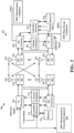
- FIG. 1 is a diagram illustrating an example of a wireless communications system and an access network 100.
- the wireless communications system (also referred to as a wireless wide area network (WWAN)) includes base stations 102, UEs 104, an Evolved Packet Core (EPC) 160, and another core network 190 (e.g., a 5G Core (5GC)).
- the base stations 102 may include macrocells (high power cellular base station) and/or small cells (low power cellular base station).
- the macrocells include base stations.
- the small cells include femtocells, picocells, and microcells.
- the base stations 102 configured for 4G LTE may interface with the EPC 160 through first backhaul links 132 (e.g., S1 interface).
- the base stations 102 configured for 5G NR may interface with core network 190 through second backhaul links 184.
- UMTS Universal Mobile Telecommunications System
- 5G NR Next Generation RAN
- the base stations 102 may perform one or more of the following functions: transfer of user data, radio channel ciphering and deciphering, integrity protection, header compression, mobility control functions (e.g., handover, dual connectivity), inter-cell interference coordination, connection setup and release, load balancing, distribution for non-access stratum (NAS) messages, NAS node selection, synchronization, radio access network (RAN) sharing, multimedia broadcast multicast service (MBMS), subscriber and equipment trace, RAN information management (RIM), paging, positioning, and delivery of warning messages.
- the base stations 102 may communicate directly or indirectly (e.g., through the EPC 160 or core network 190) with each other over third backhaul links 134 (e.g., X2 interface).
- the first backhaul links 132, the second backhaul links 184, and the third backhaul links 134 may be wired or wireless.
- the base stations 102 may wirelessly communicate with the UEs 104. Each of the base stations 102 may provide communication coverage for a respective geographic coverage area 110. There may be overlapping geographic coverage areas 110. For example, the small cell 102' may have a coverage area 110' that overlaps the coverage area 110 of one or more macro base stations 102.
- a network that includes both small cell and macrocells may be known as a heterogeneous network.
- a heterogeneous network may also include Home Evolved Node Bs (eNBs) (HeNBs), which may provide service to a restricted group known as a closed subscriber group (CSG).
- eNBs Home Evolved Node Bs
- CSG closed subscriber group
- the communication links 120 between the base stations 102 and the UEs 104 may include uplink (UL) (also referred to as reverse link) transmissions from a UE 104 to a base station 102 and/or downlink (DL) (also referred to as forward link) transmissions from a base station 102 to a UE 104.
- the communication links 120 may use multiple-input and multiple-output (MIMO) antenna technology, including spatial multiplexing, beamforming, and/or transmit diversity.
- the communication links may be through one or more carriers.
- the base stations 102 / UEs 104 may use spectrum up to YMHz (e.g., 5, 10, 15, 20, 100, 400, etc.
- the component carriers may include a primary component carrier and one or more secondary component carriers.
- a primary component carrier may be referred to as a primary cell (PCell) and a secondary component carrier may be referred to as a secondary cell (SCell).
- D2D communication link 158 may use the DL/UL WWAN spectrum.
- the D2D communication link 158 may use one or more sidelink channels, such as a physical sidelink broadcast channel (PSBCH), a physical sidelink discovery channel (PSDCH), a physical sidelink shared channel (PSSCH), and a physical sidelink control channel (PSCCH).
- sidelink channels such as a physical sidelink broadcast channel (PSBCH), a physical sidelink discovery channel (PSDCH), a physical sidelink shared channel (PSSCH), and a physical sidelink control channel (PSCCH).
- sidelink channels such as a physical sidelink broadcast channel (PSBCH), a physical sidelink discovery channel (PSDCH), a physical sidelink shared channel (PSSCH), and a physical sidelink control channel (PSCCH).
- sidelink channels such as a physical sidelink broadcast channel (PSBCH), a physical sidelink discovery channel (PSDCH), a physical sidelink shared channel (PSSCH), and a physical sidelink control channel (PSCCH).
- the wireless communications system may further include a Wi-Fi access point (AP) 150 in communication with Wi-Fi stations (STAs) 152 via communication links 154, e.g., in a 5 GHz unlicensed frequency spectrum or the like.
- AP Wi-Fi access point
- STAs Wi-Fi stations
- communication links 154 e.g., in a 5 GHz unlicensed frequency spectrum or the like.
- the STAs 152 / AP 150 may perform a clear channel assessment (CCA) prior to communicating in order to determine whether the channel is available.
- CCA clear channel assessment
- the small cell 102' may operate in a licensed and/or an unlicensed frequency spectrum. When operating in an unlicensed frequency spectrum, the small cell 102' may employ NR and use the same unlicensed frequency spectrum (e.g., 5 GHz, or the like) as used by the Wi-Fi AP 150. The small cell 102', employing NR in an unlicensed frequency spectrum, may boost coverage to and/or increase capacity of the access network.
- the small cell 102' employing NR in an unlicensed frequency spectrum, may boost coverage to and/or increase capacity of the access network.
- the electromagnetic spectrum is often subdivided, based on frequency/wavelength, into various classes, bands, channels, etc.
- frequency range designations FR1 410 MHz - 7.125 GHz
- FR2 24.25 GHz - 52.6 GHz
- the frequencies between FR1 and FR2 are often referred to as mid-band frequencies.
- FR1 is often referred to (interchangeably) as a "sub-6 GHz" band in various documents and articles.
- FR2 which is often referred to (interchangeably) as a "millimeter wave” band in documents and articles, despite being different from the extremely high frequency (EHF) band (30 GHz - 300 GHz) which is identified by the International Telecommunications Union (ITU) as a "millimeter wave” band.
- EHF extremely high frequency
- ITU International Telecommunications Union
- sub-6 GHz or the like if used herein may broadly represent frequencies that may be less than 6 GHz, may be within FR1, or may include mid-band frequencies.
- millimeter wave or the like if used herein may broadly represent frequencies that may include mid-band frequencies, may be within FR2, or may be within the EHF band.
- a base station 102 may include and/or be referred to as an eNB, gNodeB (gNB), or another type of base station.
- Some base stations, such as gNB 180 may operate in a traditional sub 6 GHz spectrum, in millimeter wave frequencies, and/or near millimeter wave frequencies in communication with the UE 104.
- the gNB 180 may be referred to as a millimeter wave base station.
- the millimeter wave base station 180 may utilize beamforming 182 with the UE 104 to compensate for the path loss and short range.
- the base station 180 and the UE 104 may each include a plurality of antennas, such as antenna elements, antenna panels, and/or antenna arrays to facilitate the beamforming.
- the base station 180 may transmit a beamformed signal to the UE 104 in one or more transmit directions 182'.
- the UE 104 may receive the beamformed signal from the base station 180 in one or more receive directions 182".
- the UE 104 may also transmit a beamformed signal to the base station 180 in one or more transmit directions.
- the base station 180 may receive the beamformed signal from the UE 104 in one or more receive directions.
- the base station 180 / UE 104 may perform beam training to determine the best receive and transmit directions for each of the base station 180 / UE 104.
- the transmit and receive directions for the base station 180 may or may not be the same.
- the transmit and receive directions for the UE 104 may or may not be the same.
- the EPC 160 may include a Mobility Management Entity (MME) 162, other MMEs 164, a Serving Gateway 166, a Multimedia Broadcast Multicast Service (MBMS) Gateway 168, a Broadcast Multicast Service Center (BM-SC) 170, and a Packet Data Network (PDN) Gateway 172.
- MME Mobility Management Entity
- MBMS Multimedia Broadcast Multicast Service
- BM-SC Broadcast Multicast Service Center
- PDN Packet Data Network
- the MME 162 may be in communication with a Home Subscriber Server (HSS) 174.
- HSS Home Subscriber Server
- the MME 162 is the control node that processes the signaling between the UEs 104 and the EPC 160.
- the MME 162 provides bearer and connection management. All user Internet protocol (IP) packets are transferred through the Serving Gateway 166, which itself is connected to the PDN Gateway 172.
- IP Internet protocol
- the PDN Gateway 172 provides UE IP address allocation as well as other functions.
- the PDN Gateway 172 and the BM-SC 170 are connected to the IP Services 176.
- the IP Services 176 may include the Internet, an intranet, an IP Multimedia Subsystem (IMS), a PS Streaming Service, and/or other IP services.
- the BM-SC 170 may provide functions for MBMS user service provisioning and delivery.
- the BM-SC 170 may serve as an entry point for content provider MBMS transmission, may be used to authorize and initiate MBMS Bearer Services within a public land mobile network (PLMN), and may be used to schedule MBMS transmissions.
- PLMN public land mobile network
- the MBMS Gateway 168 may be used to distribute MBMS traffic to the base stations 102 belonging to a Multicast Broadcast Single Frequency Network (MBSFN) area broadcasting a particular service, and may be responsible for session management (start/stop) and for collecting eMBMS related charging information.
- MMSFN Multicast Broadcast Single Frequency Network
- the core network 190 may include an Access and Mobility Management Function (AMF) 192, other AMFs 193, a Session Management Function (SMF) 194, and a User Plane Function (UPF) 195.
- the AMF 192 may be in communication with a Unified Data Management (UDM) 196.
- the AMF 192 is the control node that processes the signaling between the UEs 104 and the core network 190.
- the AMF 192 provides QoS flow and session management. All user Internet protocol (IP) packets are transferred through the UPF 195.
- the UPF 195 provides UE IP address allocation as well as other functions.
- the UPF 195 is connected to the IP Services 197.
- the IP Services 197 may include the Internet, an intranet, an IP Multimedia Subsystem (IMS), a Packet Switch (PS) Streaming (PSS) Service, and/or other IP services.
- IMS IP Multimedia Subsystem
- PS Packet Switch
- PSS Packet Switch
- the base station may include and/or be referred to as a gNB, Node B, eNB, an access point, a base transceiver station, a radio base station, a radio transceiver, a transceiver function, a basic service set (BSS), an extended service set (ESS), a transmit reception point (TRP), or some other suitable terminology.
- the base station 102 provides an access point to the EPC 160 or core network 190 for a UE 104.
- Examples of UEs 104 include a cellular phone, a smart phone, a session initiation protocol (SIP) phone, a laptop, a personal digital assistant (PDA), a satellite radio, a global positioning system, a multimedia device, a video device, a digital audio player (e.g., MP3 player), a camera, a game console, a tablet, a smart device, a wearable device, a vehicle, an electric meter, a gas pump, a large or small kitchen appliance, a healthcare device, an implant, a sensor/actuator, a display, or any other similar functioning device.
- SIP session initiation protocol
- PDA personal digital assistant
- Some of the UEs 104 may be referred to as IoT devices (e.g., parking meter, gas pump, toaster, vehicles, heart monitor, etc.).
- the UE 104 may also be referred to as a station, a mobile station, a subscriber station, a mobile unit, a subscriber unit, a wireless unit, a remote unit, a mobile device, a wireless device, a wireless communications device, a remote device, a mobile subscriber station, an access terminal, a mobile terminal, a wireless terminal, a remote terminal, a handset, a user agent, a mobile client, a client, or some other suitable terminology.
- the base station 180 may include an MDT measurement & processing component 199.
- the base station 180 may use component 199 during an RRC connection to configure a UE 104 to perform various types of MDT measurements (including providing measurement intervals and a measurement duration), to log the data into measurement reports to be received from a UE 102 pertaining to various MDT measurement types, and to receive the measurement reports and forward them to the core network for distributing to the appropriate entity.
- MDT measurements including providing measurement intervals and a measurement duration
- MMSFN Multimedia Broadcast/Multicast service Single Frequency Network
- WLAN wireless LAN
- Bluetooth measurements location measurements, etc.
- Component 199 may also be configured to perform other actions involving the MDT measurement reports, including processing MDT information, making requests for different measurement reports such as MDT measurement type requests, and sending and receiving information concerning MDT activities and measurement reports to and from the UEs 104, other base stations 102/180, the core network 190, and other network entities/clients that may require the data relevant to specific UE measurement types.
- component 199 is configured to include, in a measurement type request, an indication that the base station supports receiving MDT measurement data in data streams.
- the UE 104 may include an MDT data transmission component 198(1) and an MDT measurement component 198(2).
- the MDT measurement component 198(2) of the UE 104 may be configured to receive configuration information, including measurement intervals and a measurement duration, from the base station 180 during an RRC connection for subsequently performing MDT measurements during a UE idle state.
- the MDT component 198(2) may further be configured to perform the different MDT measurements configured previously by the base station 180.
- the MDT component 198(2) may be configured to perform these measurements during the specified measurement intervals and over the length of the MDT measurement duration. After the measurements, when the RRC connection is released, the UE 104 enters the idle state.
- the MDT component 198(2) may further be configured to log the measurement data, including storing information corresponding to different types of measurements, into different respective data files, for example.
- the MDT data transmission component 198(1) may be configured to receive MDT measurement type requests from the base station 180 during an RRC connection that occurs subsequent to performing the measurements.
- the MDT data transmission component 198(1) may be configured to receive an indication in the measurement type request that the base station supports, or is capable of, receiving MDT data in the requested. Responsive to this type of request, component 198(1) may be configured to send a structured measurement report as one or more files or as a non-real time data stream to the base station 180 which includes measurement data corresponding to the specific type of measurement identified in the MDT measurement type request from the larger group of available MDT measurements.
- Component 198(1) may also be configured, in the case where the base station identifies in the MDT measurement type request more than one type of MDT measurement, to send during successive time periods different time periods.
- MDT data transmission component 198(1) may also be configured for performing other MDT-related functions.
- the MDT measurement & processing component 199, MDT data transmission component 198(1) and MDT measurement component 198(2) may be implemented, in part or in whole, as software stored in memory and executed on one or more general purpose or specialized processors.
- these components 198(1), 198(2) and 199 may be implemented, in part or in whole, in firmware, or as hardware including one or more digital signal processors (DSPs), gate arrays, SoCs, digital logic circuits, application specific integrated circuits (ASICs), and the like.
- DSPs digital signal processors
- SoCs gate arrays
- ASICs application specific integrated circuits
- the concepts described herein may be applicable to other similar areas, such as other types of network measurements, including signal-strength and round-trip time (RTT) measurements, for example.
- RTT round-trip time
- 5G NR the concepts described herein may be applicable to other similar areas, such as LTE, LTE-A, CDMA, GSM, and other wireless technologies.
- FIG. 2A is a diagram 200 illustrating an example of a first subframe within a 5G NR frame structure.
- FIG. 2B is a diagram 230 illustrating an example of DL channels within a 5G NR subframe.
- FIG. 2C is a diagram 250 illustrating an example of a second subframe within a 5G NR frame structure.
- FIG. 2D is a diagram 280 illustrating an example of UL channels within a 5G NR subframe.
- the 5G NR frame structure may be frequency division duplexed (FDD) in which for a particular set of subcarriers (carrier system bandwidth), subframes within the set of subcarriers are dedicated for either DL or UL, or may be time division duplexed (TDD) in which for a particular set of subcarriers (carrier system bandwidth), subframes within the set of subcarriers are dedicated for both DL and UL.
- FDD frequency division duplexed
- TDD time division duplexed
- the 5G NR frame structure is assumed to be TDD, with subframe 4 being configured with slot format 28 (with mostly DL), where D is DL, U is UL, and F is flexible for use between DL/UL, and subframe 3 being configured with slot format 34 (with mostly UL). While subframes 3, 4 are shown with slot formats 34, 28, respectively, any particular subframe may be configured with any of the various available slot formats 0-61. Slot formats 0, 1 are all DL, UL, respectively. Other slot formats 2-61 include a mix of DL, UL, and flexible symbols.
- UEs are configured with the slot format (dynamically through DL control information (DCI), or semi-statically/statically through radio resource control (RRC) signaling) through a received slot format indicator (SFI).
- DCI DL control information
- RRC radio resource control
- SFI received slot format indicator
- a frame (10 ms) may be divided into 10 equally sized subframes (1 ms). Each subframe may include one or more time slots. Subframes may also include mini-slots, which may include 7, 4, or 2 symbols. Each slot may include 7 or 14 symbols, depending on the slot configuration. For slot configuration 0, each slot may include 14 symbols, and for slot configuration 1, each slot may include 7 symbols.
- the symbols on DL may be cyclic prefix (CP) OFDM (CP-OFDM) symbols.
- the symbols on UL may be CP-OFDM symbols (for high throughput scenarios) or discrete Fourier transform (DFT) spread OFDM (DFT-s-OFDM) symbols (also referred to as single carrier frequency-division multiple access (SC-FDMA) symbols) (for power limited scenarios; limited to a single stream transmission).
- the number of slots within a subframe is based on the slot configuration and the numerology. For slot configuration 0, different numerologies ⁇ 0 to 4 allow for 1, 2, 4, 8, and 16 slots, respectively, per subframe. For slot configuration 1, different numerologies 0 to 2 allow for 2, 4, and 8 slots, respectively, per subframe. Accordingly, for slot configuration 0 and numerology ⁇ , there are 14 symbols/slot and 2 ⁇ slots/subframe.
- the subcarrier spacing and symbol length/duration are a function of the numerology.
- the subcarrier spacing may be equal to 2 ⁇ * 15 kHz, where ⁇ is the numerology 0 to 4.
- the symbol length/duration is inversely related to the subcarrier spacing.
- the slot duration is 0.25 ms
- the subcarrier spacing is 60 kHz
- the symbol duration is approximately 16.67 ⁇ s.
- Each BWP may have a particular numerology.
- a resource grid may be used to represent the frame structure.
- Each time slot includes a resource block (RB) (also referred to as physical RBs (PRBs)) that extends 12 consecutive subcarriers.
- RB resource block
- PRBs physical RBs
- the resource grid is divided into multiple resource elements (REs). The number of bits carried by each RE depends on the modulation scheme.
- the RS may include demodulation RS (DM-RS) (indicated as R x for one particular configuration, where 100x is the port number, but other DM-RS configurations are possible) and channel state information reference signals (CSI-RS) for channel estimation at the UE.
- DM-RS demodulation RS
- CSI-RS channel state information reference signals
- the RS may also include beam measurement RS (BRS), beam refinement RS (BRRS), and phase tracking RS (PT-RS).
- BRS beam measurement RS
- BRRS beam refinement RS
- PT-RS phase tracking RS
- FIG. 2B illustrates an example of various DL channels within a subframe of a frame.
- the physical downlink control channel (PDCCH) carries DCI within one or more control channel elements (CCEs), each CCE including nine RE groups (REGs), each REG including four consecutive REs in an OFDM symbol.
- a PDCCH within one BWP may be referred to as a control resource set (CORESET). Additional BWPs may be located at greater and/or lower frequencies across the channel bandwidth.
- a primary synchronization signal (PSS) may be within symbol 2 of particular subframes of a frame. The PSS is used by a UE 104 to determine subframe/symbol timing and a physical layer identity.
- a secondary synchronization signal may be within symbol 4 of particular subframes of a frame.
- the SSS is used by a UE to determine a physical layer cell identity group number and radio frame timing. Based on the physical layer identity and the physical layer cell identity group number, the UE can determine a physical cell identifier (PCI). Based on the PCI, the UE can determine the locations of the aforementioned DM-RS.
- the physical broadcast channel (PBCH) which carries a master information block (MIB), may be logically grouped with the PSS and SSS to form a synchronization signal (SS)/PBCH block (also referred to as SS block (SSB)).
- the MIB provides a number of RBs in the system bandwidth and a system frame number (SFN).
- the physical downlink shared channel (PDSCH) carries user data, broadcast system information not transmitted through the PBCH such as system information blocks (SIBs), and paging messages.
- SIBs system information blocks
- some of the REs carry DM-RS (indicated as R for one particular configuration, but other DM-RS configurations are possible) for channel estimation at the base station.
- the UE may transmit DM-RS for the physical uplink control channel (PUCCH) and DM-RS for the physical uplink shared channel (PUSCH).
- the PUSCH DM-RS may be transmitted in the first one or two symbols of the PUSCH.
- the PUCCH DM-RS may be transmitted in different configurations depending on whether short or long PUCCHs are transmitted and depending on the particular PUCCH format used.
- the UE may transmit sounding reference signals (SRS).
- the SRS may be transmitted in the last symbol of a subframe.
- the SRS may have a comb structure, and a UE may transmit SRS on one of the combs.
- the SRS may be used by a base station for channel quality estimation to enable frequency-dependent scheduling on the UL.
- FIG. 2D illustrates an example of various UL channels within a subframe of a frame.
- the PUCCH may be located as indicated in one configuration.
- the PUCCH carries uplink control information (UCI), such as scheduling requests, a channel quality indicator (CQI), a precoding matrix indicator (PMI), a rank indicator (RI), and hybrid automatic repeat request (HARQ) ACK/NACK feedback.
- UCI uplink control information
- the PUSCH carries data, and may additionally be used to carry a buffer status report (BSR), a power headroom report (PHR), and/or UCI.
- BSR buffer status report
- PHR power headroom report
- FIG. 3 is a block diagram of a base station 310 in communication with a UE 350 in an access network.
- IP packets from the EPC 160 may be provided to a controller/processor 375.
- the controller/processor 375 implements layer 3 and layer 2 functionality.
- Layer 3 includes a radio resource control (RRC) layer
- layer 2 includes a service data adaptation protocol (SDAP) layer, a packet data convergence protocol (PDCP) layer, a radio link control (RLC) layer, and a medium access control (MAC) layer.
- RRC radio resource control
- SDAP service data adaptation protocol
- PDCP packet data convergence protocol
- RLC radio link control
- MAC medium access control
- the controller/processor 375 provides RRC layer functionality associated with broadcasting of system information (e.g., MIB, SIBs), RRC connection control (e.g., RRC connection paging, RRC connection establishment, RRC connection modification, and RRC connection release), inter radio access technology (RAT) mobility, and measurement configuration for UE measurement reporting; PDCP layer functionality associated with header compression / decompression, security (ciphering, deciphering, integrity protection, integrity verification), and handover support functions; RLC layer functionality associated with the transfer of upper layer packet data units (PDUs), error correction through ARQ, concatenation, segmentation, and reassembly of RLC service data units (SDUs), re-segmentation of RLC data PDUs, and reordering of RLC data PDUs; and MAC layer functionality associated with mapping between logical channels and transport channels, multiplexing of MAC SDUs onto transport blocks (TBs), demultiplexing of MAC SDUs from TBs, scheduling information reporting, error
- the transmit (TX) processor 316 and the receive (RX) processor 370 implement layer 1 functionality associated with various signal processing functions.
- Layer 1 which includes a physical (PHY) layer, may include error detection on the transport channels, forward error correction (FEC) coding/decoding of the transport channels, interleaving, rate matching, mapping onto physical channels, modulation/demodulation of physical channels, and MIMO antenna processing.
- the TX processor 316 handles mapping to signal constellations based on various modulation schemes (e.g., binary phase-shift keying (BPSK), quadrature phase-shift keying (QPSK), M-phase-shift keying (M-PSK), M-quadrature amplitude modulation (M-QAM)).
- BPSK binary phase-shift keying
- QPSK quadrature phase-shift keying
- M-PSK M-phase-shift keying
- M-QAM M-quadrature amplitude modulation
- Each stream may then be mapped to an OFDM subcarrier, multiplexed with a reference signal (e.g., pilot) in the time and/or frequency domain, and then combined together using an Inverse Fast Fourier Transform (IFFT) to produce a physical channel carrying a time domain OFDM symbol stream.
- the OFDM stream is spatially precoded to produce multiple spatial streams.
- Channel estimates from a channel estimator 374 may be used to determine the coding and modulation scheme, as well as for spatial processing.
- the channel estimate may be derived from a reference signal and/or channel condition feedback transmitted by the UE 350.
- Each spatial stream may then be provided to a different antenna 320 via a separate transmitter 318TX.
- Each transmitter 318TX may modulate an RF carrier with a respective spatial stream for transmission.
- each receiver 354RX receives a signal through its respective antenna 352.
- Each receiver 354RX recovers information modulated onto an RF carrier and provides the information to the receive (RX) processor 356.
- the TX processor 368 and the RX processor 356 implement layer 1 functionality associated with various signal processing functions.
- the RX processor 356 may perform spatial processing on the information to recover any spatial streams destined for the UE 350. If multiple spatial streams are destined for the UE 350, they may be combined by the RX processor 356 into a single OFDM symbol stream.
- the RX processor 356 then converts the OFDM symbol stream from the time-domain to the frequency domain using a Fast Fourier Transform (FFT).
- FFT Fast Fourier Transform
- the frequency domain signal comprises a separate OFDM symbol stream for each subcarrier of the OFDM signal.
- the symbols on each subcarrier, and the reference signal are recovered and demodulated by determining the most likely signal constellation points transmitted by the base station 310. These soft decisions may be based on channel estimates computed by the channel estimator 358.
- the soft decisions are then decoded and deinterleaved to recover the data and control signals that were originally transmitted by the base station 310 on the physical channel.
- the data and control signals are then provided to the controller/processor 359, which implements layer 3 and layer 2 functionality.
- the controller/processor 359 can be associated with a memory 360 that stores program codes and data.
- the memory 360 may be referred to as a computer-readable medium.
- the controller/processor 359 provides demultiplexing between transport and logical channels, packet reassembly, deciphering, header decompression, and control signal processing to recover IP packets from the EPC 160.
- the controller/processor 359 is also responsible for error detection using an ACK and/or NACK protocol to support HARQ operations.
- the controller/processor 359 provides RRC layer functionality associated with system information (e.g., MIB, SIBs) acquisition, RRC connections, and measurement reporting; PDCP layer functionality associated with header compression / decompression, and security (ciphering, deciphering, integrity protection, integrity verification); RLC layer functionality associated with the transfer of upper layer PDUs, error correction through ARQ, concatenation, segmentation, and reassembly of RLC SDUs, re-segmentation of RLC data PDUs, and reordering of RLC data PDUs; and MAC layer functionality associated with mapping between logical channels and transport channels, multiplexing of MAC SDUs onto TBs, demultiplexing of MAC SDUs from TBs, scheduling information reporting, error correction through HARQ, priority handling, and logical channel prioritization.
- RRC layer functionality associated with system information (e.g., MIB, SIBs) acquisition, RRC connections, and measurement reporting
- PDCP layer functionality associated with header compression
- Channel estimates derived by a channel estimator 358 from a reference signal or feedback transmitted by the base station 310 may be used by the TX processor 368 to select the appropriate coding and modulation schemes, and to facilitate spatial processing.
- the spatial streams generated by the TX processor 368 may be provided to different antenna 352 via separate transmitters 354TX. Each transmitter 354TX may modulate an RF carrier with a respective spatial stream for transmission.
- the UL transmission is processed at the base station 310 in a manner similar to that described in connection with the receiver function at the UE 350.
- Each receiver 318RX receives a signal through its respective antenna 320.
- Each receiver 318RX recovers information modulated onto an RF carrier and provides the information to a RX processor 370.
- the controller/processor 375 can be associated with a memory 376 that stores program codes and data.
- the memory 376 may be referred to as a computer-readable medium.
- the controller/processor 375 provides demultiplexing between transport and logical channels, packet reassembly, deciphering, header decompression, control signal processing to recover IP packets from the UE 350. IP packets from the controller/processor 375 may be provided to the EPC 160.
- the controller/processor 375 is also responsible for error detection using an ACK and/or NACK protocol to support HARQ operations.
- At least one of the TX processor 368, the RX processor 356, and the controller/processor 359 may be configured to perform aspects in connection with 198(1) and 198(2) of FIG. 1 .
- at least one of the TX processor 316, the RX processor 370, and the controller/processor 375 may be configured to perform aspects in connection with MDT measurement & processing component 199 of FIG. 1 .
- any portion or each of MDT measurement & processing component 199, MDT data transmission component 198(1) and MDT measurement component 198(2) may be configured, in part or in whole, as one or more special-purpose processors, or in other hardware implementations, e.g., those described with reference to FIG. 1 .
- RRC radio resource control
- the single file must be filtered by the core network to partition the file into a plurality of files such that each partitioned file includes only the data pertaining to one measurement type.
- This filtering is necessary because different types of measurement information may be needed by different clients or other network entities. Only after the filtering process can the data can be forwarded to the necessary client.
- FIG. 4 is a conceptual diagram 400 illustrating an example of a UE 402 establishing an RRC connection with a base station (eNB 406) and the base station forwarding measurement data to an Operations & Management (operations, administration and management/maintenance) facility 410.
- UE 402 transfers the MDT measurement report as a large file over the established RRC connection 404.
- the UE 402 may include with the reported MDT data one or more parameters from the UE's memory (such as a trace reference, trace recording session, or trace collection entity (TCE) identifier, for example).
- TCE trace collection entity
- the base station 406 which may be an eNB, gNB, or other type of base station enumerated above, may receive and reconstruct the file. The base station 406 may then extract the one or more parameters to correlate the data at the TCE that belongs to the same trace (MDT session). The base station 406 may use the TCE ID to obtain the IP address of the TCE, which in turn identifies where the MDT data should be forwarded.
- the base station 406 may establish an O&M connection 408 to O&M entity 410, which can be an entity of the core network that performs the filtering of the measurement data by type. That data can finally be passed to the correct network entities as described above.
- O&M entity 410 can be an entity of the core network that performs the filtering of the measurement data by type. That data can finally be passed to the correct network entities as described above.
- FIG. 5 is a timing diagram 500 illustrating an example of logged MDT reporting procedure between a UE 504 and a network including a base station 502 and a TCE 506.
- An RRC connection may be established at 508.
- a logged measurement configuration may be performed in which the base station 502 sends one or more messages to the UE 504 specifying all of the types of MDT measurement that the UE 504 should perform, the measurement intervals for each of the measurements, and the overall MDT measurement duration ( see, e.g., block 530).
- the base station 502 may configure the UE 504 to perform each MDT measurement required by the network.
- the UE 504 may enter the idle state. During the idle state, the UE 504 may perform the measurements and log the results as configured by the base station 502. For example, the UE 504 may perform an MDT measurement at each logging interval until a logging duration timer is expired, after which the UE 504 may perform an MDT measurement for another interval. For example, if the logging duration is ten minutes and the logging interval is 320 milliseconds (ms), then during each 320 ms interval one MDT measurement may be performed and the interval may be repeated for ten minutes. After all the measurements are performed, a large amount of data corresponding to all of the measurement reports is ready to be sent.
- ms milliseconds
- the UE 504 may optionally provide an indication to the base station 502 that the measurement logging is complete.
- the base station 502 sends a UE information request to the UE 504 asking the UE 504 to send the MDT measurement report.
- the base station may request the report without specifying measurement types, as is conventional.
- the UE 504 may send a UE information response 522 in which the single MDT measurement report is transferred as a single large file and segmented as necessary for each of the (currently 8 KB max) RRC blocks.
- the multiple RRC segmented messages may be sent as discussed above, including all the signaling overhead and the attendant UE battery drain, consuming network time until the file transfer is finally complete - only to await the next transfer by the base station 502 and further filtering step by the network.
- the base station 502 may obtain the TCE's address from the TCE ID, as described above. After sending to the TCE 506 an MDT file ready notification 526, the base station 502 may proceed to transfer the MDT file to the TCE 506 at 528, where the file may be further forwarded to the network core or portions thereof as necessary to filter the file and provide the individual measurement results to the correct entities.
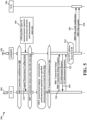
- FIG. 6 is a timing diagram 600 illustrating an example of logged MDT reporting including sending or non-real time streaming a requested type of measurement report from the UE 602 to the network including base station 604 and TCE 606 according to the main embodiment of the invention.
- an RRC connection establishment process may be initiated (608).
- the network may issue a UE capability inquiry 639.
- the UE may respond with a UE capability information message 641, inside of which a new bit may be included to indicate UE capability for streaming Logged MDT for MDT measurement type requests. While the non-real time streaming may be used, this feature is optional and the data may be transmitted as a structured file or otherwise in any manner over the network.
- the UE capable signal 641 can alternatively be included elsewhere, for example in with the subsequent RRC connection establishment and setup signal exchanges 616 and 618, and it need not be included in the current RRC connection.
- the base station 502 is already aware of the capability and it need not be explicitly conveyed by the UE 604. Thereupon, at 643 the RRC connection can be validated and completed.
- the base station signals the UE 602 and issues an indication of the measurement types the network requires, and the measurement duration and intervals, as in FIG. 5 .
- the RRC connection can be released, and the UE 604 may enter into an idle state.
- the UE 604 commences logging, and the UE 604 stores and accumulates MDT measurement results within its memory pertaining to the measurements configured in 610 by the base station 602.
- the UE 604 may store data corresponding to a single type of measurement result in one corresponding file, and the UE 604 may store data corresponding to another type of measurement result in another file, and so on for the remaining measurement intervals in the specified duration.
- the UE 604 may indicate that the connection setup is complete, and in so doing, the UE 604 may indicate to the base station 602 that the MDT measurement results are ready.
- the base station 602 performs an MDT measurement type request at 620.
- the base station 602 in FIG. 6 requests data corresponding to the type of measurement required by the network at the time of the request.
- the MDT measurement type request of the claimed embodiment includes an indication that the base station is "data stream capable", that is to say, the base station supports the capability of receiving non-real time measurement-type specific data streams in lieu of the conventional all-enveloping data file transfer.
- the non-real time streaming need not be used and the data may be sent, e.g., over a control plane using conventional transmission techniques.
- the UE 604 may optionally send a not ready / not capable indication 621 to the base station 602, in which case the devices may fall back to the legacy technique or in some configurations, the devices may omit the MDT exchange altogether. Otherwise, in one implementation, the UE 604 responds by sending a non-real time data stream or by sending directly data 622 corresponding only to the measurement report data for the type of measurement requested by the base station 602.
- the base station 602 may in the MDT measurement type request 620 send a request for two or more MDT measurements required by the network at the time of the request.
- the UE 604 sends the relevant measurement reports sequentially, with data corresponding to one type of measurement at a time.
- the UE 604 may respond by sending first data that includes data corresponding to a first type of requested measurement, and thereafter second data that includes data corresponding to a second type of requested measurement, and so on until data is sent for all the types of measurements that were requested by the base station 602 in request 620.
- the base station 602 may in step 620 make a request for a structured measurement report specific to one MDT measurement type (as above), in response to which the UE 604 may send the data including a report with results for that measurement report.
- the base station 602 may make another MDT measurement type request for data corresponding to another type of MDT measurement, in response to which the UE 604 may respond by sending the data corresponding to that MDT measurement type at 622.
- the base station 602 may issue yet additional MDT measurement type requests 620 in which data corresponding to other measurement types is requested.
- the requests in these implementations can be made in a sequential manner for one or more data types, and that data is requested and sent only when the data is needed by the network in a structured manner, rather than being arbitrarily sent as one big measurement report.
- the base station 602 may obtain a TCE address from the TCE ID sent with the data (624). The base station 602 may notify the TCE entity 606 of the anticipated transfer at 626 and thereafter the base station 602 may transfer the MDT data to the TCE 606 at 628, and the data may be forwarded to the entity that requires the information.
- the technique of FIG. 6 has several benefits to both the UE 604 and the network. Because each measurement report can be transmitted to the base station as a single type of measurement data or corresponding result, the requirement of filtering the data by the network may be obviated or reduced, and instead the data can be directly sent to the network entity that needs it. Further, because the data can optionally be sent in non-real time streams by the UE 604 depending on the type of MDT measurement, the streams are typically much smaller, and may not exceed the RRC maximum data size, meaning that the requirement to segment the data into 8 KB chunks is reduced or eliminated. This in turn can minimize the amount of RRC signaling overhead required by the network, since different data segments do not have to be managed with corresponding RRC control information.
- each measurement report for a single type of MDT measurement may correspond to a single non-real time data stream (or the data is simply transmitted using conventional techniques), bandwidth and network resources are conserved.
- This technique also eliminates the conventional problems associated with UE battery drain, since the files streamed are substantially smaller and the UE battery power status can be revisited, if necessary, following the successful transmission of a single data stream.
- the UE While only the data logged for a requested type of measurement is sent, the UE performs and logs all measurements configured by the base station as before. Therefore, the UE keeps this information at its disposal, and it can be made incumbent on the network to determine what types of MDT data are needed and when, rather than the UE (which has far more limited processing resources compared with the network), to have to track this information.
- the network can issue MDT measurement type requests corresponding to the information it needs, and the UE can send that information as a data report formatted to be responsive to the base station's specific MDT requests, for example. The remaining measurement reports can be preserved in UE unless and until that information is needed.
- FIG 7 is a flowchart 700 of a method of wireless communication according to the main embodiment of the invention.
- a UE such as the UE 104, 350 or 604 of FIGs. 1 , 3 or 6 , respectively
- a base station such as the base station 102/180, 310, or 602 of FIGs. 1 , 3 or 6 , respectively
- These measurement types may typically represent all of the different measurement types for which the network anticipates needing data over a subsequent period of time.
- the UE may optionally send a message to the base station that the UE supports the capability of sending one non-real time stream of measured MDT data for one measurement type.
- the data may be transmitted directly, without using MDT streaming. As noted above, this information may be included elsewhere in the process flow, and in some configurations it may already be understood.
- the UE can make or perform, during an ensuing idle period of the UE, the corresponding plurality of MDT measurements specified by the base station in step 702.
- the UE may log these measurements during respective intervals by saving data obtained from each of the measurements in a separate file.
- the UE may perform measurements for all configured measurement types up to the total specified measurement duration.
- the UE receives, from the base station, a request for structured minimization of driving test (MDT) data, the requested data corresponding to at least one type of MDT measurement specified by the base station from a larger plurality of available MDT measurement types that can be performed by the UE.
- MDT driving test
- the UE may receive, from a base station during a period such as during a subsequent RRC connection, a request for MDT data specifying a report for at least one type of MDT measurement from a larger number of MDT measurement types.
- the UE sends the data including results corresponding to the specified at least one type of MDT measurement to the base station at step 712.
- the UE sends at step 712 a report with the requested measurement type to the base station. If data corresponding to more than one type of measurement was requested by the base station, the UE may successively send one or more non-real time data streams or other transmissions corresponding to those one or more additional requested measurement types, one data stream at a time until all streams are transmitted and the base station successfully receives them.
- the base station includes in the message of step 710 an indication that it supports receiving MDT streams. In other configurations, the base station may provide this information at an earlier time.
- the process can end 719 at least until another such request is made or the UE receives another configuration. If, however, at step 714 the UE receives another request for data corresponding to another type (or other types) of MDT measurements required by the network, the UE again may send one non-real time data stream corresponding to one measurement type, then another data stream corresponding to another measurement type if applicable, and so on until the data is provided to the base station.
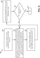
- FIG. 8 is a flowchart of a method of wireless communication according to the main embodiment of the invention from the perspective of the base station (such as the base station identified in FIGs. 7 , 6 , 3 or 1 , described above, for example).
- the base station may transmit to a UE (such as the UE identified in FIGs. 7 , 6 , 3 or 1 , described above) during an RRC connection MDT measurement configurations for a plurality of MDT measurements to be performed and logged by the UE.
- a UE such as the UE identified in FIGs. 7 , 6 , 3 or 1 , described above
- the base station at step 804 sends a request to a UE for structured minimization of driving test (MDT) data, the requested MDT data corresponding to at least one type of MDT measurement specified by the base station from a larger plurality of available MDT measurement types that can be performed by the UE.
- MDT driving test
- the base station may send a structured MDT measurement type request to the UE for a type of MDT measurement data during another RRC connection.
- the MDT measurement type request includes a data bit or other indication that the base station supports receiving the MDT information in a measurement-type specific data stream.
- the base station at step 806 receives the data including results corresponding to the specified at least one type of MDT measurement from the UE. For instance, in some embodiments, the base station may receive from the UE a non-real time data stream or other type of transmission corresponding to the requested type of measurement. If the base station identified multiple measurement types at request 804, the base station may receive a plurality of sequential data streams, each data stream corresponding to a measurement report for a single measurement type identified by the base station. Further at step 806, the base station may receive the data including results corresponding to the specified at least one type of MDT measurement from the UE. For example, the base station may receive the one or more data streams or other transmissions and save data from each of them to a separate file.
- the base station may also identify, along with the requested MDT data, TCE addresses from the data streams or other transmissions. Accordingly, at step 808, the base station may forward the requested MDT data via a trace collection entity (TCE) to a core network for distributing to clients. For example, the base station may extract information from each of the one or more data streams or other data transmissions to identify the intended TCE recipient as described above. Using this information, the base station may send the received data in a data stream or other transmission type to the TCE for forwarding to the appropriate client or entity that may require the information. In some implementations, the base station may be configured to transmit the received data directly to the entity that requested data for that measurement type. If the base station receives multiple data streams in sequence corresponding to a request for multiple measurement types, the base station, in an exemplary implementation, may send each received data stream, such as in the form of a file, for example, to the TCE for routing to the intended entity.
- TCE trace collection entity
- the base station may subsequently determine, or the base station may be subsequently informed by the network, that another one or more measurement reports corresponding to additional data types configured by the base station may be needed (810). If so, the base station may return to step 804 to issue a new MDT measurement type request identifying the new data types, and the process resumes from step 804 as described above. If no other MDT data is requested, the process ends (819) until such time that another request is made, or the UE is reconfigured, etc.
- a new information element may be added as an information element (IE) that can represent a basis for writing code to identify the type(s) of measurement for which a measurement report is required.
- an octet bit string (XXXXXXXX) may be used to enable the base station to identify the type of measurement.
- a Bluetooth measurement may be represented by the fourth bit position in the octet (i.e., XXXXXXXX)
- a WLAN measurement may be represented by the seventh bit position (XXXXXXXX).
- the measurement types may be enabled by setting the relevant bits to "1" or "true”.
- the base station may provide the bit string 01001000, for example, which identifies those to tests.
- An MDT information type request may optionally include the following IE for a 5G NR network, for example.
- the octet in the example above can be predefined to have any value from 0 to 7. Specifying a 1 enables a stream ID corresponding to the MDT measurement type. In configurations where additional measurement types are required, a larger bit string, or multiple bit strings, can be used. Code or hardware that may implement this IE or a similar IE can be used to define the MDT measurement type to be selected in an actual device.
- the MDT Stream from the UE can be tagged with a stream ID, (e.g., cell measurements, MDT Stream (serving and neighbors), IRAT measurement stream, MBSFN MDT measurement stream, WLAN MDT measurement stream, BT MDT measurement stream, and the like) to distinguish between different types of MDT information.
- a stream ID e.g., cell measurements, MDT Stream (serving and neighbors), IRAT measurement stream, MBSFN MDT measurement stream, WLAN MDT measurement stream, BT MDT measurement stream, and the like
- the base station may inform the UE that the base station supports the selective MDT report capability.
- a data bit or other indicator may be added to the base station's MDT measurement type report.
- an IE indicating non-real time MDT streaming support can be optionally added as follows:
- the Boolean value can be optionally set to "true” to indicate non real-time MDT streaming capability. Once this bit is set to true, then the base station can issue the MDT measurement type request.
- IEs above are exemplary only, and other IEs or hardware and software implementations are possible for use in various configurations described in this disclosure. Thus the IEs are not intended to be limiting, but rather purely illustrative in nature.
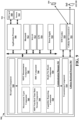
- FIG. 9 is a diagram illustrating an example of a hardware implementation 900 for an example UE 902.
- the UE 902 may include a cellular baseband processor 904 (also referred to as a modem) coupled to a cellular RF transceiver 922 and one or more subscriber identity modules (SIM) cards 920, an application processor 906 coupled to a secure digital (SD) card 908 and a screen 910, a Bluetooth module 912, a wireless local area network (WLAN) module 914, a Global Positioning System (GPS) module 916, and a power supply 918.
- the cellular baseband processor 904 may communicate through the cellular RF transceiver 922 with the UE 104 and/or base station 102/180.
- the cellular baseband processor 904 may include a computer-readable medium / memory.
- the computer-readable medium / memory may be non-transitory.
- the cellular baseband processor 904 may be responsible for general processing, including the execution of software stored on the computer-readable medium / memory.
- the software when executed by the cellular baseband processor 904, may cause the cellular baseband processor 904 to perform the various functions described throughout this disclosure.
- the computer-readable medium / memory may also be used for storing data that is manipulated by the cellular baseband processor 904 when executing software.
- the cellular baseband processor 904 may further include a reception component 930, a communication manager 932, and a transmission component 934.
- the communication manager 932 may include the one or more illustrated components.
- the components within the communication manager 932 may be stored in the computer-readable medium / memory and/or configured as hardware within the cellular baseband processor 904.
- the cellular baseband processor 904 may be a component of the UE 350 and may include the memory 360 and/or at least one of the TX processor 368, the RX processor 356, and the controller/processor 359.
- the UE 902 may include a modem chip and the baseband processor 904, and may include the aforediscussed additional modules of the UE 902.
- the communication manager 932 can include a measurement types component 940 that may be internal to the UE and that may be used as needed to store data and code used to assist in performing MDT measurements.
- the communication manager 932 can further include an MDT measurement component 942 that optionally receives input in the form of information and code from component 940 for performing different measurements and that also optionally receives information from the reception component 930 such as MDT configurations from the base station.
- the MDT measurement component 940 may be configured to receive MDT configuration information, including measurement intervals and a measurement duration as described in step 702 from FIG 7 and signal(s) 610 from FIG. 6 .
- the MDT measurement component 942 may be configured to perform the different types of MDT measurements over the measurement intervals and the MDT duration provided by the base station 180, as shown in step 706 of FIG. 7 and block 614 of FIG. 6 .
- the MDT measurement component 942 may also use input in the form of UE-specific measurement information from the measurement types component 940.
- the MDT measurement component 942 is also configured to perform these measurements when the UE 104 is in an idle state.
- the MDT measurement component 942 may be configured to log the measurement data, including storing information corresponding to different types of measurements into different respective data files, e.g., as described in connection with step 706 and 708 of FIG. 7 and blocks 612 and 614 of FIG. 6 .
- the communication manager 932 may further include a non-real time MDT data stream component 944 that can receive input in the form of measurement data from the component 942 and that may be configured to receive MDT measurement type requests from the base station during an RRC connection, e.g., as described in connection with step 710 of FIG. 7 and signal(s) 620 of FIG. 6 .
- the MDT data stream component 944 may be configured to receive an indication in the measurement type request that the base station supports receiving MDT type-specific data streams, e.g., as is also shown in step 7 of FIG. 7 .
- MDT data stream component 944 may be configured to send a non-real time data stream to the base station 180 which includes measurement data corresponding to the information requested in the MDT measurement type request, e.g., as shown in step 712 of FIG. 7 and signal 622 of FIG. 6 .
- Component 944 may also be configured, in the case where the base station identifies in the MDT measurement type request more than one type of MDT measurement, to send different non-real time data streams during successive time periods, with each data stream corresponding to one data type, e.g., as shown in steps 710, 712 and 714 of FIG. 7 and signal 622 and block 647 of FIG. 6 .
- the communication manager 932 may further include an RRC component 946 that can receive input in the form of RRC connection/release requests from the reception component 930 and is configured to establish or release an RRC connection.
- the communication manager 932 may further include a capability reporting component 948 that receives input in the form of a configuration message or an MDT measurement type request from the components 942 and 944 and is configured to optionally send an indication to the base station that the UE is capable of MDT measurement-type specific data streaming, e.g., as described in connection with step 704 of FIG. 7 and signal 641 and block 645 of FIG. 6 .
- the communication manager 932 further may include a ready/not ready component 950 that receives input from the MDT data stream component 944 in the form of an MDT measurement type request and that is configured to indicate to the base station that it is ready or not ready, or not capable, of sending the requested data stream, e.g., as show in signal 621 of FIG. 6 .
- a ready/not ready component 950 that receives input from the MDT data stream component 944 in the form of an MDT measurement type request and that is configured to indicate to the base station that it is ready or not ready, or not capable, of sending the requested data stream, e.g., as show in signal 621 of FIG. 6 .
- the UE may include additional components that perform each of the blocks of the algorithm in the aforementioned timing diagram and flowchart of FIGs. 6 and 7 , respectively. As such, each block in the aforementioned timing diagrams and flowcharts of FIGs. 6 and 7 , respectively, may be performed by a component and the UE may include one or more of those components.
- the components may be one or more hardware components specifically configured to carry out the stated processes/algorithm, implemented by a processor configured to perform the stated processes/algorithm, stored within a computer-readable medium for implementation by a processor, or some combination thereof.
- the UE 902 includes means for receiving, from a base station, a request for minimization of driving test (MDT) data corresponding to a type of measurement by the UE, means for sending a data stream comprising the requested data to the base station, means for making a plurality of MDT measurements specified by the base station, and means for saving each of the plurality of measurements in a separate file.
- the aforementioned means may be one or more of the aforementioned components of the UE 902 configured to perform the functions recited by the aforementioned means.
- the UE 902 may include the TX Processor 368, the RX Processor 356, and the controller/processor 359.
- the aforementioned means may be the TX Processor 368, the RX Processor 356, and the controller/processor 359 configured to perform the functions recited by the aforementioned means.
- FIG. 10 is a diagram 1000 illustrating an example of a hardware implementation for a base station 1002.
- the base station 1002 includes a baseband unit 1004.
- the baseband unit 1004 may communicate through a cellular RF transceiver with the UE 104.
- the baseband unit 1004 may include a computer-readable medium / memory.
- the baseband unit 1004 is responsible for general processing, including the execution of software stored on the computer-readable medium / memory.
- the software when executed by the baseband unit 1004, causes the baseband unit 1004 to perform the various functions described above.
- the computer-readable medium / memory may also be used for storing data that is manipulated by the baseband unit 1004 when executing software.
- the baseband unit 1004 further includes a reception component 1030, a communication manager 1032, and a transmission component 1034.
- the communication manager 1032 includes the one or more illustrated components.
- the components within the communication manager 1032 may be stored in the computer-readable medium / memory and/or configured as hardware within the baseband unit 1004.
- the baseband unit 1004 may be a component of the base station 310 and may include the memory 376 and/or at least one of the TX processor 316, the RX processor 370, and the controller/processor 375.
- the communication manager 1032 may include an MDT configuration component 1040 that is configured to send an MDT configuration message to a UE for configuring a plurality of different MDT measurement types for the UE to perform, as well as to provide the UE with specified measurement intervals and an MDT measurement duration, e.g., as described in connection with step 802 of FIG. 8 and step 610 and block 630 of FIG. 6 .
- the communication manager 1032 further includes an MDT data stream component 1042 that receives input in the form of MDT measurement configuration type, measurement parameters, and measurement intervals and duration from the MDT configuration component 1040, and that is configured to send an MDT measurement type message to the UE e.g., as described in connection with steps 804 and 810 of FIG. 8 and signal 620 of FIG.
- the communication manager 1032 further includes an MDT processing component 1044 that is configured to receive input in the form of data streams from component 1042 and is configured to receive the data streams and optionally save them into individual files, e.g., as described in connection with step 806 of FIG. 8 .
- the communication manager 932 may further include an RRC component 1046 that receives input in the form of RRC connection/release requests from the reception component 1030 and is configured to establish or release an RRC connection.
- the communication manager 932 further receives a network component 1048 that is configured to receive input in the form of data streams from component 1042 and/or data files from component 1044 and to extract TCE information from the data to identify a TCE address for sending the data file to the correct TCE entity, e.g., as described in connection with step 808 of FIG. 8 and signals 622, 626 and 628 and block 624 of FIG. 6 .
- the communication manager 932 further receives a legacy enabling component 1050 that receives input from the reception component 1030 in the form of information as to the measurement-type data streaming capabilities, or lack thereof, sent from the UE.
- the base station may include additional components that perform each of the blocks of the algorithm in the aforementioned timing diagram and flowchart of FIGs. 6 and 8 , respectively. As such, each block in the aforementioned flowcharts of FIGs. 6 and 8 , respectively, may be performed by a component and the base station may include one or more of those components.
- the components may be one or more hardware components specifically configured to carry out the stated processes/algorithm, implemented by a processor configured to perform the stated processes/algorithm, stored within a computer-readable medium for implementation by a processor, or some combination thereof.
- the base station 1002 includes means for sending a request to a UE for minimization of driving test (MDT) data corresponding to a type of measurement by the UE, and means for receiving a stream comprising the requested data corresponding to the type of measurement.
- the aforementioned means may be one or more of the aforementioned components of the base station 1002 configured to perform the functions recited by the aforementioned means.
- the base station 1002 may include the TX Processor 316, the RX Processor 370, and the controller/processor 375.
- the aforementioned means may be the TX Processor 316, the RX Processor 370, and the controller/processor 375 configured to perform the functions recited by the aforementioned means.
- one or more aspects of the present disclosure may enable the network to selectively identify requested data for MDT measurements that are pertinent at the time of request, thereby reducing or eliminating the network resources expended on filtering the data.
- the data can also be streamed from the UE on a type-specific basis.
- the data streams can be far smaller than the conventional data file inclusive of all measurements and the possibility of requiring that the streamed data be segmented is reduced or eliminated. This in turn can reduce or eliminate the resource bottlenecks associated with excessive RRC signaling. Additionally, the problem regarding the power drain on the battery may be mitigated or solved.
- Combinations such as "at least one of A, B, or C,” “one or more of A, B, or C,” “at least one of A, B, and C,” “one or more of A, B, and C,” and "A, B, C, or any combination thereof' include any combination of A, B, and/or C, and may include multiples of A, multiples of B, or multiples of C.
- combinations such as “at least one of A, B, or C,” “one or more of A, B, or C,” “at least one of A, B, and C,” “one or more of A, B, and C,” and “A, B, C, or any combination thereof' may be A only, B only, C only, A and B, A and C, B and C, or A and B and C, where any such combinations may contain one or more member or members of A, B, or C.
Landscapes
- Engineering & Computer Science (AREA)
- Computer Networks & Wireless Communication (AREA)
- Signal Processing (AREA)
- Mobile Radio Communication Systems (AREA)
Claims (14)
- Procédé de communication sans fil exécuté par un équipement utilisateur, UE, comprenant les étapes consistant à :recevoir (710), d'une station de base, une demande de minimisation structurée de données récupérées sur l'état de réseau, MDT, les données demandées correspondant à au moins un type de mesure MDT spécifié par la station de base parmi une plus grande pluralité de types de mesure MDT disponibles qui peut être effectué par l'UE, la demande de données MDT structurées comprenant une indication selon laquelle la station de base prend en charge des données MDT transmises en flux continu en différé ; etenvoyer (712) les données comprenant les résultats correspondant au(x) type(s) spécifié(s) de mesure MDT à la station de base.
- Procédé selon la revendication 1, dans lequel l'envoi des données à la station de base comprend en outre l'envoi d'un rapport structuré identifiant l'au moins un type spécifié de mesure MDT.
- Procédé selon la revendication 1, comprenant en outre l'exécution d'une mesure correspondant à l'au moins un type spécifié de mesure MDT.
- Procédé selon la revendication 1, comprenant en outre l'envoi des données à la station de base sur un plan de contrôle.
- Procédé selon la revendication 1, dans lequel les données MDT demandées comprennent des résultats spécifiques à au moins un type de mesure MDT spécifié par la station de base.
- Procédé selon la revendication 1, comprenant en outre l'envoi, à la station de base, d'informations comprenant un bit de capacité pour indiquer une prise en charge sélective du rapport MDT.
- Procédé selon la revendication 1, comprenant en outre les étapes consistant à :recevoir, après l'envoi des données, une autre demande de la station de base concernant des données MDT structurées comprenant des résultats correspondant à un autre type de mesure MDT spécifié par la station de base ; etenvoyer les données demandées à la station de base correspondant à l'autre type de mesure MDT.
- Procédé selon la revendication 1, comprenant en outre les étapes consistant à :effectuer une mesure correspondant audit type de mesure MDT spécifié par la station de base ;enregistrer les résultats de la mesure dans un fichier séparé ; etenvoyer le fichier séparé comprenant les résultats à la station de base.
- Procédé selon la revendication 1, comprenant en outre l'étape consistant à:envoyer un message à la station de base indiquant que l'UE n'est pas prêt à transmettre les données MDT demandées,les résultats étant ensuite envoyés à la station de base lorsque l'UE est prêt.
- Procédé selon la revendication 9, dans lequel le message comprend un message d'informations d'assistance à l'UE envoyé en réponse à la demande de données MDT structurées pour notifier à la station de base que l'UE n'est pas actuellement prêt ou capable de transmettre les données MDT demandées.
- Procédé selon la revendication 1, dans lequel les résultats sont envoyés en utilisant la diffusion des données en flux continu en différé.
- Un équipement utilisateur, UE, comprenant :une mémoire; etau moins un processeur couplé à la mémoire et configuré pour :recevoir (710), d'une station de base, une demande de minimisation structurée de données récupérées sur l'état de réseau, MDT, les données demandées correspondant à au moins un type de mesure MDT spécifié par la station de base parmi une plus grande pluralité de types de mesure MDT disponibles qui peut être effectué par l'UE, la demande de données MDT structurées comprenant une indication selon laquelle la station de base prend en charge des données MDT transmises en flux continu en différé ; etenvoyer (712) les données comprenant les résultats correspondant au(x) type(s) spécifié(s) de mesure MDT à la station de base.
- Procédé de communication sans fil exécuté par une station de base, comprenant les étapes consistant à :envoyer (804) une demande à un UE pour une minimisation structurée de données récupérées sur l'état de réseau, MDT, les données MDT demandées correspondant à au moins un type de mesure MDT spécifié par la station de base parmi une plus grande pluralité de types de mesure MDT disponibles qui peuvent être effectuée par l'UE, la demande de données MDT structurées comprenant une indication selon laquelle la station de base prend en charge des données MDT transmises en flux continu en différé ; etrecevoir (806) les données comprenant des résultats correspondant audit au moins un type spécifié de mesure MDT en provenance de l'UE.
- Une station de base, comprenant :une mémoire; etau moins un processeur couplé à la mémoire et configuré pour :envoyer (804) une demande à un UE pour une minimisation structurée de données récupérées sur l'état de réseau, MDT, les données MDT demandées correspondant à au moins un type de mesure MDT spécifié par la station de base parmi une plus grande pluralité de types de mesure MDT disponibles qui peuvent être effectuée par l'UE, la demande de données MDT structurées comprenant une indication selon laquelle la station de base prend en charge des données MDT transmises en flux continu en différé ; etrecevoir (806) les données comprenant les résultats correspondant au(x) type(s) spécifié(s) de mesure MDT en provenance de l'UE.
Applications Claiming Priority (2)
| Application Number | Priority Date | Filing Date | Title |
|---|---|---|---|
| IN202041030556 | 2020-07-17 | ||
| PCT/US2021/039556 WO2022015499A1 (fr) | 2020-07-17 | 2021-06-29 | Minimisation structurée de données de mesure de test d'entraînement d'un équipement utilisateur à un réseau |
Publications (2)
| Publication Number | Publication Date |
|---|---|
| EP4183165A1 EP4183165A1 (fr) | 2023-05-24 |
| EP4183165B1 true EP4183165B1 (fr) | 2024-10-30 |
Family
ID=76845315
Family Applications (1)
| Application Number | Title | Priority Date | Filing Date |
|---|---|---|---|
| EP21745631.8A Active EP4183165B1 (fr) | 2020-07-17 | 2021-06-29 | Minimisation structurée de données de mesure de test d'entraînement d'un équipement utilisateur à un réseau |
Country Status (4)
| Country | Link |
|---|---|
| US (1) | US12549986B2 (fr) |
| EP (1) | EP4183165B1 (fr) |
| CN (1) | CN115777209B (fr) |
| WO (1) | WO2022015499A1 (fr) |
Families Citing this family (2)
| Publication number | Priority date | Publication date | Assignee | Title |
|---|---|---|---|---|
| EP4245059A1 (fr) * | 2020-11-11 | 2023-09-20 | Telefonaktiebolaget LM Ericsson (publ) | Validation de rapport de minimisation des tests de conduite |
| US20250240658A1 (en) * | 2021-10-20 | 2025-07-24 | Nokia Technologies Oy | Criteria-based measurement reporting |
Family Cites Families (11)
| Publication number | Priority date | Publication date | Assignee | Title |
|---|---|---|---|---|
| CN102907132B (zh) * | 2010-02-16 | 2016-04-13 | 瑞典爱立信有限公司 | 报告非实时mdt测量 |
| KR102247818B1 (ko) * | 2011-08-10 | 2021-05-04 | 삼성전자 주식회사 | 이동통신 시스템에서 복수의 캐리어를 이용해서 데이터를 전송하는 방법 및 장치 |
| US20150044973A1 (en) * | 2012-03-07 | 2015-02-12 | Telefonaktiebolaget L M Ericsson (Publ) | Node and method for handling non-real time data in a wireless communications network |
| KR102064377B1 (ko) | 2012-05-09 | 2020-02-12 | 삼성전자 주식회사 | 이동 통신 시스템에서 측정 정보 송수신 방법 및 장치 |
| US11069441B2 (en) * | 2015-10-28 | 2021-07-20 | Phc Holdings Corporation | Biological information measurement device and biological information measurement method |
| US20180324869A1 (en) * | 2017-05-04 | 2018-11-08 | Qualcomm Incorporated | Uplink early data transmission |
| ES2971053T3 (es) | 2018-03-27 | 2024-06-03 | Beijing Xiaomi Mobile Software Co Ltd | Método y aparato para medir dispositivo Bluetooth |
| CN110958633B (zh) * | 2018-09-27 | 2022-08-12 | 北京三星通信技术研究有限公司 | 最小化路测测量的配置方法、上报方法以及接入网设备 |
| CN115150873B (zh) | 2018-09-27 | 2025-12-19 | 北京三星通信技术研究有限公司 | 最小化路测测量的配置方法、上报方法以及接入网设备 |
| WO2020221455A1 (fr) * | 2019-05-02 | 2020-11-05 | Nokia Technologies Oy | Gestion de contextes de minimisation d'essais de conduite multiples dans des états de contrôleur de ressources radio multiples |
| US20230297882A1 (en) * | 2020-07-07 | 2023-09-21 | Nokia Technologies Oy | Ml ue capability and inability |
-
2021
- 2021-06-29 EP EP21745631.8A patent/EP4183165B1/fr active Active
- 2021-06-29 WO PCT/US2021/039556 patent/WO2022015499A1/fr not_active Ceased
- 2021-06-29 CN CN202180048568.9A patent/CN115777209B/zh active Active
- 2021-06-29 US US17/999,818 patent/US12549986B2/en active Active
Also Published As
| Publication number | Publication date |
|---|---|
| EP4183165A1 (fr) | 2023-05-24 |
| US20230180042A1 (en) | 2023-06-08 |
| US12549986B2 (en) | 2026-02-10 |
| CN115777209A (zh) | 2023-03-10 |
| CN115777209B (zh) | 2026-04-14 |
| WO2022015499A1 (fr) | 2022-01-20 |
Similar Documents
| Publication | Publication Date | Title |
|---|---|---|
| JP7574233B2 (ja) | Rrc状態の間でのue支援型高速遷移 | |
| US12213121B2 (en) | Signaling-overhead reduction with resource grouping | |
| EP4223043B1 (fr) | Capacité dynamique pour de multiples modules d'identité d'abonné universels | |
| AU2020292176B2 (en) | Methods and apparatus to facilitate spatial relation indication for uplink control channel and sounding reference signals | |
| KR20230113297A (ko) | 셀룰러 네트워크들에서 협력 머신 러닝을 위한 모델 발견 및 선택 | |
| US11963214B2 (en) | Measurement gap and scheduling | |
| US12082015B2 (en) | Data collection for non-public networks | |
| US12193036B2 (en) | Time domain resource allocation-based HARQ-ACK feedback generation | |
| EP4062682B1 (fr) | Rapport de capacité d'appareil utilisateur pour signaux de référence d'affaiblissement le long du trajet configurés et activés | |
| US11601930B2 (en) | Early termination of PUSCH transmission | |
| US12452780B2 (en) | Fast slicing switching via SCG suspension or activation | |
| US12604282B2 (en) | Uplink spatial filter and power control for channel estimation across physical uplink control channels | |
| US20240023090A1 (en) | Configuring uplink transmission configuration indicator list | |
| EP4183165B1 (fr) | Minimisation structurée de données de mesure de test d'entraînement d'un équipement utilisateur à un réseau | |
| US20200196336A1 (en) | Gap transmission in channel occupancy time | |
| US12349052B2 (en) | UE assistance information for slices | |
| WO2022236775A1 (fr) | Reprise après défaillance de faisceau dans des systèmes de communication sans fil utilisant de multiples points d'émission/réception | |
| WO2022052028A1 (fr) | Procédés et appareils d'améliorations de fiabilité de réseaux de communication machine massive (mmtc) | |
| WO2021253267A1 (fr) | Procédé de traitement en dehors d'une zone de service de réseau de données local (ladn) | |
| WO2022000470A1 (fr) | Procédé et appareil pour gérer un transfert intercellulaire entre technologies d'accès radio |
Legal Events
| Date | Code | Title | Description |
|---|---|---|---|
| STAA | Information on the status of an ep patent application or granted ep patent |
Free format text: STATUS: UNKNOWN |
|
| STAA | Information on the status of an ep patent application or granted ep patent |
Free format text: STATUS: THE INTERNATIONAL PUBLICATION HAS BEEN MADE |
|
| PUAI | Public reference made under article 153(3) epc to a published international application that has entered the european phase |
Free format text: ORIGINAL CODE: 0009012 |
|
| STAA | Information on the status of an ep patent application or granted ep patent |
Free format text: STATUS: REQUEST FOR EXAMINATION WAS MADE |
|
| 17P | Request for examination filed |
Effective date: 20221122 |
|
| AK | Designated contracting states |
Kind code of ref document: A1 Designated state(s): AL AT BE BG CH CY CZ DE DK EE ES FI FR GB GR HR HU IE IS IT LI LT LU LV MC MK MT NL NO PL PT RO RS SE SI SK SM TR |
|
| DAV | Request for validation of the european patent (deleted) | ||
| DAX | Request for extension of the european patent (deleted) | ||
| RIC1 | Information provided on ipc code assigned before grant |
Ipc: H04W 8/24 20090101ALN20240325BHEP Ipc: H04W 24/08 20090101ALN20240325BHEP Ipc: H04W 24/10 20090101AFI20240325BHEP |
|
| GRAP | Despatch of communication of intention to grant a patent |
Free format text: ORIGINAL CODE: EPIDOSNIGR1 |
|
| STAA | Information on the status of an ep patent application or granted ep patent |
Free format text: STATUS: GRANT OF PATENT IS INTENDED |
|
| RIC1 | Information provided on ipc code assigned before grant |
Ipc: H04W 8/24 20090101ALN20240426BHEP Ipc: H04W 24/08 20090101ALN20240426BHEP Ipc: H04W 24/10 20090101AFI20240426BHEP |
|
| INTG | Intention to grant announced |
Effective date: 20240528 |
|
| GRAS | Grant fee paid |
Free format text: ORIGINAL CODE: EPIDOSNIGR3 |
|
| GRAA | (expected) grant |
Free format text: ORIGINAL CODE: 0009210 |
|
| STAA | Information on the status of an ep patent application or granted ep patent |
Free format text: STATUS: THE PATENT HAS BEEN GRANTED |
|
| AK | Designated contracting states |
Kind code of ref document: B1 Designated state(s): AL AT BE BG CH CY CZ DE DK EE ES FI FR GB GR HR HU IE IS IT LI LT LU LV MC MK MT NL NO PL PT RO RS SE SI SK SM TR |
|
| REG | Reference to a national code |
Ref country code: GB Ref legal event code: FG4D |
|
| REG | Reference to a national code |
Ref country code: CH Ref legal event code: EP |
|
| REG | Reference to a national code |
Ref country code: IE Ref legal event code: FG4D |
|
| REG | Reference to a national code |
Ref country code: DE Ref legal event code: R096 Ref document number: 602021021047 Country of ref document: DE |
|
| REG | Reference to a national code |
Ref country code: LT Ref legal event code: MG9D |
|
| REG | Reference to a national code |
Ref country code: NL Ref legal event code: MP Effective date: 20241030 |
|
| PG25 | Lapsed in a contracting state [announced via postgrant information from national office to epo] |
Ref country code: IS Free format text: LAPSE BECAUSE OF FAILURE TO SUBMIT A TRANSLATION OF THE DESCRIPTION OR TO PAY THE FEE WITHIN THE PRESCRIBED TIME-LIMIT Effective date: 20250228 Ref country code: HR Free format text: LAPSE BECAUSE OF FAILURE TO SUBMIT A TRANSLATION OF THE DESCRIPTION OR TO PAY THE FEE WITHIN THE PRESCRIBED TIME-LIMIT Effective date: 20241030 Ref country code: PT Free format text: LAPSE BECAUSE OF FAILURE TO SUBMIT A TRANSLATION OF THE DESCRIPTION OR TO PAY THE FEE WITHIN THE PRESCRIBED TIME-LIMIT Effective date: 20250228 |
|
| PG25 | Lapsed in a contracting state [announced via postgrant information from national office to epo] |
Ref country code: NL Free format text: LAPSE BECAUSE OF FAILURE TO SUBMIT A TRANSLATION OF THE DESCRIPTION OR TO PAY THE FEE WITHIN THE PRESCRIBED TIME-LIMIT Effective date: 20241030 Ref country code: FI Free format text: LAPSE BECAUSE OF FAILURE TO SUBMIT A TRANSLATION OF THE DESCRIPTION OR TO PAY THE FEE WITHIN THE PRESCRIBED TIME-LIMIT Effective date: 20241030 |
|
| REG | Reference to a national code |
Ref country code: AT Ref legal event code: MK05 Ref document number: 1738145 Country of ref document: AT Kind code of ref document: T Effective date: 20241030 |
|
| PG25 | Lapsed in a contracting state [announced via postgrant information from national office to epo] |
Ref country code: BG Free format text: LAPSE BECAUSE OF FAILURE TO SUBMIT A TRANSLATION OF THE DESCRIPTION OR TO PAY THE FEE WITHIN THE PRESCRIBED TIME-LIMIT Effective date: 20241030 |
|
| PG25 | Lapsed in a contracting state [announced via postgrant information from national office to epo] |
Ref country code: ES Free format text: LAPSE BECAUSE OF FAILURE TO SUBMIT A TRANSLATION OF THE DESCRIPTION OR TO PAY THE FEE WITHIN THE PRESCRIBED TIME-LIMIT Effective date: 20241030 |
|
| PG25 | Lapsed in a contracting state [announced via postgrant information from national office to epo] |
Ref country code: NO Free format text: LAPSE BECAUSE OF FAILURE TO SUBMIT A TRANSLATION OF THE DESCRIPTION OR TO PAY THE FEE WITHIN THE PRESCRIBED TIME-LIMIT Effective date: 20250130 |
|
| PG25 | Lapsed in a contracting state [announced via postgrant information from national office to epo] |
Ref country code: LV Free format text: LAPSE BECAUSE OF FAILURE TO SUBMIT A TRANSLATION OF THE DESCRIPTION OR TO PAY THE FEE WITHIN THE PRESCRIBED TIME-LIMIT Effective date: 20241030 Ref country code: GR Free format text: LAPSE BECAUSE OF FAILURE TO SUBMIT A TRANSLATION OF THE DESCRIPTION OR TO PAY THE FEE WITHIN THE PRESCRIBED TIME-LIMIT Effective date: 20250131 Ref country code: AT Free format text: LAPSE BECAUSE OF FAILURE TO SUBMIT A TRANSLATION OF THE DESCRIPTION OR TO PAY THE FEE WITHIN THE PRESCRIBED TIME-LIMIT Effective date: 20241030 |
|
| PG25 | Lapsed in a contracting state [announced via postgrant information from national office to epo] |
Ref country code: PL Free format text: LAPSE BECAUSE OF FAILURE TO SUBMIT A TRANSLATION OF THE DESCRIPTION OR TO PAY THE FEE WITHIN THE PRESCRIBED TIME-LIMIT Effective date: 20241030 |
|
| PG25 | Lapsed in a contracting state [announced via postgrant information from national office to epo] |
Ref country code: RS Free format text: LAPSE BECAUSE OF FAILURE TO SUBMIT A TRANSLATION OF THE DESCRIPTION OR TO PAY THE FEE WITHIN THE PRESCRIBED TIME-LIMIT Effective date: 20250130 |
|
| PG25 | Lapsed in a contracting state [announced via postgrant information from national office to epo] |
Ref country code: SM Free format text: LAPSE BECAUSE OF FAILURE TO SUBMIT A TRANSLATION OF THE DESCRIPTION OR TO PAY THE FEE WITHIN THE PRESCRIBED TIME-LIMIT Effective date: 20241030 |
|
| PGFP | Annual fee paid to national office [announced via postgrant information from national office to epo] |
Ref country code: DE Payment date: 20250509 Year of fee payment: 5 |
|
| PG25 | Lapsed in a contracting state [announced via postgrant information from national office to epo] |
Ref country code: DK Free format text: LAPSE BECAUSE OF FAILURE TO SUBMIT A TRANSLATION OF THE DESCRIPTION OR TO PAY THE FEE WITHIN THE PRESCRIBED TIME-LIMIT Effective date: 20241030 |
|
| PGFP | Annual fee paid to national office [announced via postgrant information from national office to epo] |
Ref country code: GB Payment date: 20250508 Year of fee payment: 5 |
|
| PG25 | Lapsed in a contracting state [announced via postgrant information from national office to epo] |
Ref country code: EE Free format text: LAPSE BECAUSE OF FAILURE TO SUBMIT A TRANSLATION OF THE DESCRIPTION OR TO PAY THE FEE WITHIN THE PRESCRIBED TIME-LIMIT Effective date: 20241030 |
|
| PGFP | Annual fee paid to national office [announced via postgrant information from national office to epo] |
Ref country code: FR Payment date: 20250512 Year of fee payment: 5 |
|
| PG25 | Lapsed in a contracting state [announced via postgrant information from national office to epo] |
Ref country code: RO Free format text: LAPSE BECAUSE OF FAILURE TO SUBMIT A TRANSLATION OF THE DESCRIPTION OR TO PAY THE FEE WITHIN THE PRESCRIBED TIME-LIMIT Effective date: 20241030 |
|
| PG25 | Lapsed in a contracting state [announced via postgrant information from national office to epo] |
Ref country code: SK Free format text: LAPSE BECAUSE OF FAILURE TO SUBMIT A TRANSLATION OF THE DESCRIPTION OR TO PAY THE FEE WITHIN THE PRESCRIBED TIME-LIMIT Effective date: 20241030 |
|
| PG25 | Lapsed in a contracting state [announced via postgrant information from national office to epo] |
Ref country code: CZ Free format text: LAPSE BECAUSE OF FAILURE TO SUBMIT A TRANSLATION OF THE DESCRIPTION OR TO PAY THE FEE WITHIN THE PRESCRIBED TIME-LIMIT Effective date: 20241030 |
|
| PG25 | Lapsed in a contracting state [announced via postgrant information from national office to epo] |
Ref country code: IT Free format text: LAPSE BECAUSE OF FAILURE TO SUBMIT A TRANSLATION OF THE DESCRIPTION OR TO PAY THE FEE WITHIN THE PRESCRIBED TIME-LIMIT Effective date: 20241030 |
|
| REG | Reference to a national code |
Ref country code: DE Ref legal event code: R097 Ref document number: 602021021047 Country of ref document: DE |
|
| PLBE | No opposition filed within time limit |
Free format text: ORIGINAL CODE: 0009261 |
|
| STAA | Information on the status of an ep patent application or granted ep patent |
Free format text: STATUS: NO OPPOSITION FILED WITHIN TIME LIMIT |
|
| PG25 | Lapsed in a contracting state [announced via postgrant information from national office to epo] |
Ref country code: SE Free format text: LAPSE BECAUSE OF FAILURE TO SUBMIT A TRANSLATION OF THE DESCRIPTION OR TO PAY THE FEE WITHIN THE PRESCRIBED TIME-LIMIT Effective date: 20241030 |
|
| 26N | No opposition filed |
Effective date: 20250731 |
|
| REG | Reference to a national code |
Ref country code: CH Ref legal event code: H13 Free format text: ST27 STATUS EVENT CODE: U-0-0-H10-H13 (AS PROVIDED BY THE NATIONAL OFFICE) Effective date: 20260127 |
|
| PG25 | Lapsed in a contracting state [announced via postgrant information from national office to epo] |
Ref country code: MC Free format text: LAPSE BECAUSE OF FAILURE TO SUBMIT A TRANSLATION OF THE DESCRIPTION OR TO PAY THE FEE WITHIN THE PRESCRIBED TIME-LIMIT Effective date: 20241030 |
|
| PG25 | Lapsed in a contracting state [announced via postgrant information from national office to epo] |
Ref country code: LU Free format text: LAPSE BECAUSE OF NON-PAYMENT OF DUE FEES Effective date: 20250629 |
|
| REG | Reference to a national code |
Ref country code: BE Ref legal event code: MM Effective date: 20250630 |
|
| PG25 | Lapsed in a contracting state [announced via postgrant information from national office to epo] |
Ref country code: IE Free format text: LAPSE BECAUSE OF NON-PAYMENT OF DUE FEES Effective date: 20250629 |
|
| PG25 | Lapsed in a contracting state [announced via postgrant information from national office to epo] |
Ref country code: BE Free format text: LAPSE BECAUSE OF NON-PAYMENT OF DUE FEES Effective date: 20250630 |
|
| PG25 | Lapsed in a contracting state [announced via postgrant information from national office to epo] |
Ref country code: CH Free format text: LAPSE BECAUSE OF NON-PAYMENT OF DUE FEES Effective date: 20250630 |