EP4183276A1 - Aerosolerzeugungsvorrichtung mit vibrationseinheit und steuerungsverfahren dafür - Google Patents
Aerosolerzeugungsvorrichtung mit vibrationseinheit und steuerungsverfahren dafür Download PDFInfo
- Publication number
- EP4183276A1 EP4183276A1 EP22820399.8A EP22820399A EP4183276A1 EP 4183276 A1 EP4183276 A1 EP 4183276A1 EP 22820399 A EP22820399 A EP 22820399A EP 4183276 A1 EP4183276 A1 EP 4183276A1
- Authority
- EP
- European Patent Office
- Prior art keywords
- aerosol
- heating element
- vibration part
- vibration
- generation device
- Prior art date
- Legal status (The legal status is an assumption and is not a legal conclusion. Google has not performed a legal analysis and makes no representation as to the accuracy of the status listed.)
- Granted
Links
Images


Classifications
-
- A—HUMAN NECESSITIES
- A24—TOBACCO; CIGARS; CIGARETTES; SIMULATED SMOKING DEVICES; SMOKERS' REQUISITES
- A24F—SMOKERS' REQUISITES; MATCH BOXES; SIMULATED SMOKING DEVICES
- A24F40/00—Electrically operated smoking devices; Component parts thereof; Manufacture thereof; Maintenance or testing thereof; Charging means specially adapted therefor
- A24F40/85—Maintenance, e.g. cleaning
-
- A—HUMAN NECESSITIES
- A24—TOBACCO; CIGARS; CIGARETTES; SIMULATED SMOKING DEVICES; SMOKERS' REQUISITES
- A24F—SMOKERS' REQUISITES; MATCH BOXES; SIMULATED SMOKING DEVICES
- A24F40/00—Electrically operated smoking devices; Component parts thereof; Manufacture thereof; Maintenance or testing thereof; Charging means specially adapted therefor
- A24F40/40—Constructional details, e.g. connection of cartridges and battery parts
-
- A—HUMAN NECESSITIES
- A24—TOBACCO; CIGARS; CIGARETTES; SIMULATED SMOKING DEVICES; SMOKERS' REQUISITES
- A24F—SMOKERS' REQUISITES; MATCH BOXES; SIMULATED SMOKING DEVICES
- A24F40/00—Electrically operated smoking devices; Component parts thereof; Manufacture thereof; Maintenance or testing thereof; Charging means specially adapted therefor
- A24F40/40—Constructional details, e.g. connection of cartridges and battery parts
- A24F40/46—Shape or structure of electric heating means
-
- A—HUMAN NECESSITIES
- A24—TOBACCO; CIGARS; CIGARETTES; SIMULATED SMOKING DEVICES; SMOKERS' REQUISITES
- A24F—SMOKERS' REQUISITES; MATCH BOXES; SIMULATED SMOKING DEVICES
- A24F40/00—Electrically operated smoking devices; Component parts thereof; Manufacture thereof; Maintenance or testing thereof; Charging means specially adapted therefor
- A24F40/40—Constructional details, e.g. connection of cartridges and battery parts
- A24F40/46—Shape or structure of electric heating means
- A24F40/465—Shape or structure of electric heating means specially adapted for induction heating
-
- A—HUMAN NECESSITIES
- A24—TOBACCO; CIGARS; CIGARETTES; SIMULATED SMOKING DEVICES; SMOKERS' REQUISITES
- A24F—SMOKERS' REQUISITES; MATCH BOXES; SIMULATED SMOKING DEVICES
- A24F40/00—Electrically operated smoking devices; Component parts thereof; Manufacture thereof; Maintenance or testing thereof; Charging means specially adapted therefor
- A24F40/50—Control or monitoring
-
- A—HUMAN NECESSITIES
- A24—TOBACCO; CIGARS; CIGARETTES; SIMULATED SMOKING DEVICES; SMOKERS' REQUISITES
- A24F—SMOKERS' REQUISITES; MATCH BOXES; SIMULATED SMOKING DEVICES
- A24F40/00—Electrically operated smoking devices; Component parts thereof; Manufacture thereof; Maintenance or testing thereof; Charging means specially adapted therefor
- A24F40/20—Devices using solid inhalable precursors
-
- A—HUMAN NECESSITIES
- A24—TOBACCO; CIGARS; CIGARETTES; SIMULATED SMOKING DEVICES; SMOKERS' REQUISITES
- A24F—SMOKERS' REQUISITES; MATCH BOXES; SIMULATED SMOKING DEVICES
- A24F40/00—Electrically operated smoking devices; Component parts thereof; Manufacture thereof; Maintenance or testing thereof; Charging means specially adapted therefor
- A24F40/50—Control or monitoring
- A24F40/51—Arrangement of sensors
-
- A—HUMAN NECESSITIES
- A24—TOBACCO; CIGARS; CIGARETTES; SIMULATED SMOKING DEVICES; SMOKERS' REQUISITES
- A24F—SMOKERS' REQUISITES; MATCH BOXES; SIMULATED SMOKING DEVICES
- A24F40/00—Electrically operated smoking devices; Component parts thereof; Manufacture thereof; Maintenance or testing thereof; Charging means specially adapted therefor
- A24F40/50—Control or monitoring
- A24F40/53—Monitoring, e.g. fault detection
Definitions
- the present disclosure relates to an aerosol generation device having a vibration part and a control method thereof, and more particularly, to an aerosol generation device having a vibration part configured to vibrate a heating element, thus being capable of preventing a formation of fixed matter on the heating element and removing formed fixed matter, and a control method of the device.
- Korean Patent Registration No. 10-1667124 relates to a device heating a cigarette to generate an aerosol and deals with a structure of a holder that assists in an operation of inserting or separating a cigarette into or from the aerosol generation device.
- the user When using the aerosol generation device having such a structure, the user performs an operation of inserting a cigarette into the holder extracted to the outside of the aerosol generation device and pushing the holder and the cigarette into the aerosol generation device before smoking, and performs a task of causing the holder to protrude out of the aerosol generation device and removing the cigarette from the holder after smoking.
- the holder simply serves to guide the insertion and removal of the cigarette and thus cannot prevent residues generated from the cigarette during smoking from remaining in an inner space of the aerosol generation device or on components thereof such as a heating element.
- the user removes the cigarette inserted into the holder by holding the cigarette in his or her hand and pulling the cigarette out of the holder, and due to a high fixing strength, fixed matter (e.g., a tobacco component) formed on a contact surface between the cigarette and the heating element mostly remains on the heating element without being detached even after the cigarette is removed. Therefore, the cleanliness of the aerosol generation device is gradually lowered with the use of the device. Further, the fixed matter formed on the heating element is condensed by heat and more firmly fixed with the use of the device and thus may cause a burnt taste during smoking.
- fixed matter e.g., a tobacco component
- Some embodiments of the present disclosure are directed to providing an aerosol generation device capable of preventing a formation of fixed matter on a heating element, thus improving the cleanliness of the device.
- Some embodiments of the present disclosure are also directed to providing an aerosol generation device having a function of removing fixed matter formed on a heating element, thus improving the cleanliness of the device.
- Some embodiments of the present disclosure are also directed to providing an aerosol generation device capable of improving an ease of insertion/removal of a heating element into/from an aerosol-generating article.
- Some embodiments of the present disclosure are also directed to providing an aerosol generation device capable of improving a smoking quality of an aerosol-generating article.
- Some embodiments of the present disclosure provide an aerosol generation device including a housing configured to form an accommodation space in which an aerosol-generating article is accommodated, a heating element inserted into the aerosol-generating article accommodated in the accommodation space and configured to heat the accommodated aerosol-generating article to generate an aerosol, a vibration part configured to vibrate the heating element, and a controller configured to control the vibration part.
- the vibration part may vibrate the heating element in a vertical direction of the accommodated aerosol-generating article.
- the controller may operate the vibration part while the heating element is being inserted into the aerosol-generating article.
- the controller may operate the vibration part at a time point at which smoking ends or while the accommodated aerosol-generating article is being removed.
- the controller may control an operation of the vibration part on the basis of a predetermined time condition.
- the controller may operate the vibration part in response to determination that a temperature of the heating element is a reference value or higher.
- the controller may operate the vibration part in response to a detection of a user's puff.
- Some embodiments of the present disclosure provide a control method of an aerosol generation device having a heating element inserted into an aerosol-generating article and a vibration part configured to vibrate the heating element, the control method including determining whether a predetermined condition is satisfied and operating the vibration part in response to determination that the predetermined condition is satisfied.
- Some embodiments of the present disclosure provide a computer program that is associated with hardware and stored in computer-readable recording media to execute determining whether a predetermined condition is satisfied and, in response to a determination that the predetermined condition is satisfied, using a vibration part to vibrate a heating element inserted into an aerosol-generating article.
- an aerosol generation device having a vibration part can be provided.
- the provided aerosol generation device can vibrate a heating element using the vibration part to prevent formation of fixed matter on the heating element or remove formed fixed matter.
- a fine gap is formed between the heating element and an aerosol-forming substrate, and thus the aerosol-forming substrate can be prevented from being fixed onto a surface of the heating element, and a local carbonization phenomenon of the aerosol-forming substrate can also be prevented. Accordingly, the cleanliness of the aerosol generation device can be improved, and since a problem that fixed matter causes a burnt taste is also significantly mitigated, the overall smoking quality can also be improved.
- the ease of insertion of the heating element can be improved (that is, the heating element can be easily inserted into the aerosol-generating article).
- the ease of removal of the heating element can also be improved.
- the vibration part can be operated on the basis of a time condition, a temperature condition, and/or a puff condition. Accordingly, operational efficiency of the vibration part can be improved. For example, by operating the vibration part at a time point at which the probability of formation of fixed matter is high on the basis of any of the above conditions, power consumption of the vibration part can be reduced, and simultaneously, formation of fixed matter can also be effectively prevented.
- first, second, A, B, (a), and (b) may be used. Such terms are only used for distinguishing one component from another component, and the essence, order, sequence, or the like of the corresponding component is not limited by the terms.
- a certain component is described as being “connected,” “coupled,” or “linked” to another component, it should be understood that, although the component may be directly connected or linked to the other component, still another component may also be “connected,” “coupled,” or “linked” between the two components.
- aerosol-forming substrate may refer to a material that is able to form an aerosol.
- the aerosol may include a volatile compound.
- the aerosol-forming substrate may be a solid or liquid.
- solid aerosol-forming substrates may include solid materials based on tobacco raw materials such as reconstituted tobacco leaves, shredded tobacco, and reconstituted tobacco
- liquid aerosol-forming substrates may include liquid compositions based on nicotine, tobacco extracts, moisturizers, and/or various flavoring agents.
- liquid may refer to a liquid aerosol-forming substrate.
- aerosol-generating article may refer to an article that is able to generate an aerosol.
- the aerosol-generating article may include an aerosol-forming substrate.
- a typical example of the aerosol-generating article may include a cigarette, but the scope of the present disclosure is not limited thereto.
- aerosol generation device may refer to a device that generates an aerosol using an aerosol-forming substrate in order to generate an aerosol that can be inhaled directly into a user's lungs through the user's mouth.
- puff' refers to inhalation by a user, and the inhalation may be a situation in which a user draws smoke into his or her oral cavity, nasal cavity, or lungs through the mouth or nose.
- upstream or upstream direction may refer to a direction moving away from an oral region of a user
- downstream or downstream direction may refer to a direction approaching the oral region of the user.
- upstream and downstream may be used to describe relative positions of components constituting an aerosol-generating article.
- a filter part 21 is disposed downstream from or in a downstream direction of an aerosol-forming substrate part 22, and the aerosol-forming substrate part 22 is disposed upstream from or in an upstream direction of the filter part 21.
- longitudinal direction may refer to a direction corresponding to a longitudinal axis of an aerosol-generating article.
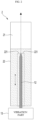
- FIG. 1 is an exemplary view schematically illustrating an aerosol generation device 1 according to some embodiments of the present disclosure.
- the aerosol generation device 1 may include a housing 11, a heater part, a vibration part 13, a controller 14, and a battery 15.
- the aerosol generation device 1 may further include general-purpose components other than the components illustrated in FIG. 1 .
- the aerosol generation device 1 may further include an output module (e.g., a motor, a display) configured to output a state of the device and/or an input module (e.g., a button) for receiving a user input (e.g., on/off of the device).
- an output module e.g., a motor, a display
- an input module e.g., a button
- the housing 11 may form an exterior of the aerosol generation device 1. Also, the housing 11 may form an accommodation space in which the aerosol-generating article 2 is accommodated. The aerosol-generating article 2 accommodated in the accommodation space may generate an aerosol when heated by a heating element 12 of the heater part, and the generated aerosol may be inhaled by a user through an oral region of the user.
- the housing 11 may be made of a suitable material that can protect components therein.
- the aerosol-generating article 2 may have a structure similar to a structure of a general combustion-type cigarette.
- the aerosol-generating article 2 may be divided into the aerosol-forming substrate part 22 which includes an aerosol-forming substrate and the filter part 21 which includes a filter material. At least a portion of the aerosol-forming substrate part 22 may be accommodated (inserted) in the aerosol generation device 1, and the filter part 21 may be exposed to the outside, but the present disclosure is not limited thereto. A user may smoke while holding the filter part 21 in his or her mouth.
- the heater part may heat the aerosol-generating article 2 accommodated in the accommodation space in order to generate an aerosol.
- the heater part may include the heating element 12 inserted into the aerosol-generating article 2, and the heating element 12 may heat the aerosol-forming substrate of the aerosol-generating article 2 from inside using power supplied from the battery 15 in order to generate an aerosol.
- the operation of the heater part may be controlled by the controller 14.
- the shape of the heating element 12 may vary.
- the heating element 12 may have a shape that can easily be inserted into the aerosol-generating article 2, such as a rod shape or a blade shape.
- the shape of the heating element 12 is not limited thereto, and the heating element 12 may also have a cylindrical or semi-cylindrical shape.
- the heating element 12 having a cylindrical shape may evenly heat the central portion and outer periphery portion of the aerosol-generating article 2 from inside the aerosol-generating article 2, thus further improving the smoking quality.
- the cylindrical shape has a problem that ease of insertion of the heating element 12 into the aerosol-generating article 2 is somewhat reduced, and such a problem can be addressed by vibrating (e.g., vertically vibrating) the heating element 12 while the heating element 12 is being inserted.
- an operation method and/or an implementation form of the heater part may also vary.
- the heater part may operate using a resistive heating method.
- the heater part may include an electrically insulating substrate (e.g., a substrate formed of polyimide) and an electrically conductive track, and an electrically resistive heating element 12 configured to generate heat as current flows may be included in the electrically conductive track.
- the heater part may operate using an induction heating method.
- the heater part may include an inductor and a heating element 12 (that is, a susceptor) inductively heated by the inductor.
- a heating element 12 that is, a susceptor
- An example of the inductor may include an induction coil, but the scope of the present disclosure is not limited thereto.
- the induction coil may be disposed in a form that surrounds at least a portion of the aerosol-generating article 2 accommodated in the accommodation space.
- the heater part may operate using any other method as long as the heater part can heat the aerosol-generating article 2 to a desired temperature.
- the desired temperature may be preset in the aerosol generation device 1 (e.g., a temperature profile may be pre-stored therein) or may be set by the user.
- the vibration part 13 may vibrate the heating element 12.
- the vibration part 13 may be configured to be mechanically (physically) interlocked with the heating element 12 (e.g., the vibration part 13 may be disposed to come in close contact with the heating element 12), and vibration generated in the vibration part 13 may be delivered to the heating element 12.
- the heating element 12 is vibrated due to the vibration part 13
- formation of fixed matter on the heating element 12 during smoking can be prevented, and the fixed matter formed on the heating element 12 can be removed.
- a local carbonization phenomenon of the aerosol-forming substrate can be mitigated, thus improving the smoking quality, and ease of insertion/removal of the heating element 12 into/from the aerosol-generating article 2 can also be improved.
- the operation of the vibration part 13 may be controlled by the controller 14. This will be described in detail below with reference to FIG. 4 and so on.
- a direction in which the vibration part 13 vibrates, a structure in which the vibration part 13 is interlocked with the heating element 12, an implementation method of the vibration part 13, a control method of the vibration part 13, or the like may be designed in various ways and may vary according to embodiments.
- the vibration part 13 may vibrate the heating element 12 in a vertical direction of the aerosol-generating article 2 (that is, a longitudinal direction thereof; refer to the dotted arrow). In that way, ease of insertion/removal of the heating element 12 into/from the aerosol-generating article 2 can be improved, and an aerosol-forming substrate of an area 221 adjacent to the heating element 12 can be effectively prevented from being fixed onto the heating element 12. Of course, fixed matter already formed on the heating element 12 can be easily removed from the heating element 12 by vibration.
- the vibration part 13 may vibrate the heating element 12 in a horizontal direction of the aerosol-generating article 2 or vibrate the heating element 12 in a twist form (e.g., a form in which twist vibration is applied to the heating element 12).
- a twist form e.g., a form in which twist vibration is applied to the heating element 12.
- a fine gap may be easily formed between the heating element 12 and the aerosol-forming substrate of the area 221 adjacent to the heating element 12, and thus the local carbonization phenomenon can be prevented more effectively.
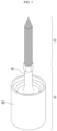
- the vibration part 13 may consist of a vibration main body 132 and a holder 131, and the heating element 12 may be mounted on (coupled to) the holder 131.
- the vibration main body 132 may serve to generate vibration
- the holder 131 may serve to fix (support) the heating element 12 while delivering the generated vibration to the heating element 12.
- the effects according to the vibration part 13 e.g., prevention of formation of fixed matter, removal of fixed matter, etc.
- the holder 131 may have an elongated shape (e.g., a horn shape) that protrudes from the vibration main body 132, but the shape of the holder 131 is not limited thereto.
- the vibration part 13 may be implemented on the basis of a piezoelectric element (e.g., an ultrasonic vibrator) that converts an electrical signal into physical vibration using a piezoelectric effect.
- a piezoelectric element e.g., an ultrasonic vibrator
- the vibration part 13 is not limited thereto and may be implemented in any other way.
- an electrical signal applied to the vibration part 13 may have a frequency in a range of about 20 KHz to 40 KHz, but the electrical signal is not limited thereto.
- the vibration part 13 may have a vibration direction changing function.
- the vibration part 13 may be configured to include a first sub-vibration part that generates vibration in a vertical direction and a second sub-vibration part that generates vibration in a horizontal direction, and may be configured to operate at least one sub-vibration part as necessary.
- the vibration part 13 may vibrate the heating element 12 in another vibration direction in some cases. For instance, while the heating element 12 is being inserted into the aerosol-generating article 2 or being removed therefrom, the vibration part 13 may vibrate the heating element 12 in the vertical direction to ensure the ease of insertion/removal of the heating element 12 and allow removal of fixed matter formed on the heating element 12.
- the vibration part 13 may intermittently vibrate the heating element 12 in the horizontal direction to allow a fine gap to be easily formed between the heating element 12 and the aerosol-forming substrate adjacent thereto. In that way, the local carbonization phenomenon and the formation of fixed matter can be effectively prevented.
- the controller 14 may control the overall operation of the aerosol generation device 1.
- the controller 14 may control the operation of the vibration part 13, the heater part, and the battery 15 and may also control the operation of other components included in the aerosol generation device 1.
- the controller 14 may control the operation of the vibration part 13 (e.g., the on/off of vibration, a vibration speed, a vibration intensity, a vibration direction, etc.), the power supplied by the battery 15, the heating operation of the heater part, and the like.
- the controller 14 may check a state of each of the components of the aerosol generation device 1 and determine whether the aerosol generation device 1 is in an operable state.
- controller 14 The operation of the controller 14 will be described in more detail below with reference to FIG. 4 .
- the controller 14 may be implemented with at least one processor.
- the processor may also be implemented with an array of a plurality of logic gates or implemented with a combination of a general-purpose microprocessor and a memory which stores a program that may be executed by the microprocessor.
- the controller 14 may also be implemented with other forms of hardware.
- the battery 15 may supply power used to operate the aerosol generation device 1.
- the battery 15 may supply power to the vibration part 13 and the heater part and may supply power required for the operation of the controller 14.
- the battery 15 may supply power necessary to operate electric components such as a display (not illustrated), a sensor (not illustrated), and a motor (not illustrated) that are installed in the aerosol generation device 1.
- the aerosol generation device 1 has been described above with reference to FIGS. 1 to 3 .
- the aerosol generation device 1 having the vibration part 13 may be provided.
- the aerosol generation device 1 may vibrate the heating element 12 using the vibration part 13 to prevent formation of fixed matter on the heating element 12 and allow removal of fixed matter formed on the heating element 12. Accordingly, the cleanliness of the aerosol generation device 1 can be improved, and a problem that fixed matter causes a burnt taste can also be significantly mitigated.
- each step of the control method which will be described below may be performed by a controller (e.g., 14; or a processor) of the aerosol generation device (e.g., 1). Also, each step of the control method may be implemented using one or more instructions executed by the controller (e.g., 14) of the aerosol generation device (e.g., 1).
- description will be continued assuming that each step of the control method is performed by the controller 14 of the aerosol generation device 1 illustrated in FIG. 1 . Therefore, in the following description, when the subject of a specific operation is omitted, the specific operation may be understood as being performed by the controller 14.
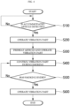
- FIG. 4 is an exemplary flowchart schematically illustrating a control method of an aerosol generation device according to some embodiments of the present disclosure. However, this is only an exemplary embodiment for achieving the objectives of the present disclosure, and of course, some steps may be added or omitted as necessary.
- control method may begin by step S100 in which the controller 14 determines whether the aerosol-generating article 2 is accommodated in the accommodation space. Whether the aerosol-generating article 2 is accommodated may be determined by the controller 14 using any method.
- the controller 14 may operate the vibration part 13 in response to determination that the aerosol-generating article 2 is accommodated. That is, the controller 14 may operate the vibration part 13 while the heating element 12 is being inserted into the aerosol-generating article 2.
- the heating element 12 since the heating element 12 is inserted into the aerosol-generating article 2 while being vibrated (e.g., vibrated in the vertical direction), the heating element 12 can be easily inserted into the aerosol-generating article 2.
- the heating element 12 has a cylindrical shape instead of a rod shape or a blade shape, by help of vibration, the heating element 12 can be easily inserted into the aerosol-generating article 2.
- step S300 the controller 14 may preheat the accommodated aerosol-generating article 2 using the heating element 12. Also, the controller 14 may operate the vibration part 13 while the aerosol-generating article 2 is being preheated. In this case, formation of fixed matter on the vibration part 13 or an occurrence of the local carbonization phenomenon due to a sharp temperature rise of the heating element 12 that occurs while the heating element 12 preheats the aerosol-generating article 2 can be prevented.
- step S400 the controller 14 may control the vibration part 13 during smoking. That is, after the preheating ends, the controller 14 may appropriately control the vibration part 13 from the start of smoking until the end of smoking.
- a specific control method may vary according to embodiments.
- the controller 14 may control the vibration part 13 according to a predetermined time condition. In other words, the controller 14 may operate the vibration part 13 during a designated amount of time at a designated time point. For example, the controller 14 may periodically operate the vibration part 13 during smoking. As another example, the controller 14 may operate the vibration part 13 at a designated smoking time point (e.g., 3 seconds after the start of smoking, 7 seconds after the start of smoking, 12 seconds after the start of smoking, 3 seconds before the end of smoking, upon the end of smoking, 1 second after the end of smoking, etc.) regardless of a period.
- a designated smoking time point e.g., 3 seconds after the start of smoking, 7 seconds after the start of smoking, 12 seconds after the start of smoking, 3 seconds before the end of smoking, upon the end of smoking, 1 second after the end of smoking, etc.
- the controller 14 may control the vibration part 13 according to a predetermined temperature condition. The present embodiment will be described in detail below with reference to FIG. 5 .
- the controller 14 may control the vibration part 13 according to a predetermined puff condition. The present embodiment will be described in detail below with reference to FIG. 6 .
- the controller 14 may determine whether smoking has ended. For example, the controller 14 may determine an end of smoking on the basis of a puff number (e.g., determine that smoking has ended when 8 puffs have been made), elapsed time after the start of smoking (e.g., determine that smoking has ended when 30 seconds have elapsed after the start of smoking), whether a puff has not been detected for a predetermined amount of time or more (e.g., determine that smoking has ended when a puff has not been detected for 2 seconds or more), a user input indicating an end of smoking, or a combination thereof.
- a puff number e.g., determine that smoking has ended when 8 puffs have been made
- elapsed time after the start of smoking e.g., determine that smoking has ended when 30 seconds have elapsed after the start of smoking
- a puff has not been detected for a predetermined amount of time or more e.g., determine that smoking has ended when a puff has not been detected for 2 seconds or more
- step S600 the controller 14 may operate the vibration part 13 in response to determination that smoking has ended.
- the controller 14 may operate the vibration part 13 at a time point at which smoking ends.
- the cleanliness of the aerosol generation device 1 can be improved. Further, a problem that fixed matter formed on the heating element 12 causes a burnt taste to be expressed during subsequent smoking can also be addressed.
- the controller 14 may operate the vibration part 13 while the aerosol-generating article 2 is being removed.
- the aerosol-generating article 2 can be easily removed from the aerosol generation device 1 (that is, the heating element 12 can be easily removed from the aerosol-generating article 2), and the fixed matter removal effect can be further enhanced.
- the controller 14 may control a vibration speed, a vibration duration, and/or a vibration intensity of the vibration part 13 on the basis of a predetermined condition.
- the controller 14 may vibrate the heating element 12 with a relatively high intensity during smoking and may vibrate the heating element 12 with a relatively low intensity at a time point at which the aerosol-generating article 2 is being accommodated/removed.
- a phenomenon in which the aerosol-generating article 2 shakes due to vibration when the aerosol-generating article 2 is being accommodated/removed can be effectively prevented, and formation of fixed matter on the aerosol-generating article 2 can also be effectively prevented.
- the controller 14 may vibrate the heating element 12 with a higher intensity after smoking ends as compared to during smoking. In this case, fixed matter formed on the heating element 12 during smoking can be effectively removed.
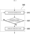
- FIG. 5 is an exemplary flowchart illustrating a method of controlling a vibration part according to some embodiments of the present disclosure.
- the present embodiment relates to a method of controlling the vibration part 13 on the basis of a temperature condition of the heating element 12.
- the method according to the present embodiment may begin by step S410 in which the controller 14 monitors a temperature of the heating element 12.
- the controller 14 may monitor the temperature of the heating element 12 using a temperature sensor.
- the scope of the present disclosure is not limited thereto, and the temperature of the heating element 12 may be monitored in any other way.
- the controller 14 may determine whether the monitored temperature is a reference value or higher.
- the reference value may be a preset fixed value or variable value that changes according to situations.
- the controller 14 may operate the vibration part 13 in response to determination that the monitored temperature is the reference value or higher.
- the controller 14 may operate the vibration part 13 in response to determination that a speed (slope) of an increase of the monitored temperature is the reference value or higher. This is because the higher the temperature of heat generated by the heating element 12, the higher the probability of formation of fixed matter due to the aerosol-forming substrate, which is adjacent to the heating element 12, being condensed by the heat.
- the controller 14 may control the vibration speed, vibration duration, and/or vibration intensity of the vibration part 13 on the basis of a temperature condition. For example, the controller 14 may increase the vibration speed, vibration duration, and/or vibration intensity of the vibration part 13 as the monitored temperature increases (or the speed of an increase of the temperature increases). This is because the higher the temperature of the heating element 12, the higher the probability of formation of fixed matter and the higher the fixing strength of the formed fixed matter. Conversely, the controller 14 may decrease the vibration speed, vibration duration, and/or vibration intensity of the vibration part 13 as the monitored temperature decreases (or the speed of a decrease of the temperature increases).
- the vibration part 13 may be operated at an appropriate time point based on a temperature condition. Accordingly, operational efficiency of the vibration part 13 can be improved. For example, by operating the vibration part 13 at a time point at which the probability of formation of fixed matter is high on the basis of a temperature condition, power consumption of the vibration part 13 can be reduced, and formation of fixed matter can also be effectively prevented.
- FIG. 6 is an exemplary flowchart illustrating a method of controlling a vibration part according to some other embodiments of the present disclosure.
- the present embodiment relates to a method of controlling the vibration part 13 on the basis of a user's puff condition.
- the method according to the present embodiment may begin by step S440 in which the controller 14 monitors a user's puff (e.g., whether a puff is made, a puff intensity, etc.).
- a user's puff e.g., whether a puff is made, a puff intensity, etc.
- the controller 14 may monitor the user's puff using an airflow sensor.
- the scope of the present disclosure is not limited thereto, and a user's puff may be monitored in any other way.
- step S450 the controller 14 may determine whether a user's puff is detected during monitoring.
- the controller 14 may operate the vibration part 13 in response to determination that a puff is detected. For example, the controller 14 may operate the vibration part 13 from a time point at which a puff is detected until the puff ends (that is, by as much as a length of the puff). This is because, upon a puff, heating of the aerosol-generating article 2 is accelerated due to an airflow entering the aerosol-generating article 2, and thus the probability of formation of fixed matter on the heating element 12 increases.
- the controller 14 may also control the vibration speed, vibration duration, and/or vibration intensity of the vibration part 13 on the basis of a puff condition.
- the controller 14 may control the vibration speed, vibration duration, and/or vibration intensity of the vibration part 13 on the basis of a puff intensity (e.g., increase the vibration speed, vibration duration, and/or vibration intensity of the vibration part 13 with an increase in the puff intensity).
- the controller 14 may control the vibration speed, vibration duration, and/or vibration intensity on the basis of a puff length or a puff interval (e.g., increase the vibration speed, vibration duration, and/or vibration intensity with an increase in the puff length or a decrease in the puff interval).
- the vibration part 13 may be operated at an appropriate time point based on a puff condition. Accordingly, operational efficiency of the vibration part 13 can be improved. For example, by operating the vibration part 13 at a time point at which the probability of formation of fixed matter is high on the basis of a puff condition, power consumption of the vibration part 13 can be reduced, and formation of fixed matter can also be effectively prevented.
- the technical spirit of the present disclosure described above with reference to FIGS. 1 to 6 may be implemented with computer-readable code on computer-readable recording media.
- Examples of the computer-readable recording media may include removable recording media (a compact disc (CD), a digital versatile disc (DVD), a Blu-Ray disk, a Universal Serial Bus (USB) storage device, or a removable hard disk) or non-removable recording media (a read-only memory (ROM), a random access memory (RAM), or a built-in hard disk).
- Computer programs recorded in the computer-readable recording media may be sent to other computing devices through a network, such as the Internet, and installed on the other computing devices to be used in the other computing devices.
Landscapes
- Catching Or Destruction (AREA)
- Resistance Heating (AREA)
Applications Claiming Priority (2)
| Application Number | Priority Date | Filing Date | Title |
|---|---|---|---|
| KR1020210075806A KR102630398B1 (ko) | 2021-06-11 | 2021-06-11 | 진동부를 구비한 에어로졸 발생 장치 및 그의 제어 방법 |
| PCT/KR2022/005750 WO2022260270A1 (ko) | 2021-06-11 | 2022-04-21 | 진동부를 구비한 에어로졸 발생 장치 및 그의 제어 방법 |
Publications (3)
| Publication Number | Publication Date |
|---|---|
| EP4183276A1 true EP4183276A1 (de) | 2023-05-24 |
| EP4183276A4 EP4183276A4 (de) | 2024-03-20 |
| EP4183276B1 EP4183276B1 (de) | 2025-12-10 |
Family
ID=84426101
Family Applications (1)
| Application Number | Title | Priority Date | Filing Date |
|---|---|---|---|
| EP22820399.8A Active EP4183276B1 (de) | 2021-06-11 | 2022-04-21 | Aerosolerzeugungsvorrichtung mit vibrationseinheit |
Country Status (6)
| Country | Link |
|---|---|
| US (1) | US12527360B2 (de) |
| EP (1) | EP4183276B1 (de) |
| JP (1) | JP7537676B2 (de) |
| KR (1) | KR102630398B1 (de) |
| CN (1) | CN116322396A (de) |
| WO (1) | WO2022260270A1 (de) |
Families Citing this family (2)
| Publication number | Priority date | Publication date | Assignee | Title |
|---|---|---|---|---|
| CN118680347A (zh) * | 2023-03-24 | 2024-09-24 | 深圳麦时科技有限公司 | 清洁方法、清洁装置、气溶胶产生装置及存储介质 |
| TW202439992A (zh) * | 2023-04-06 | 2024-10-16 | 瑞士商傑太日煙國際股份有限公司 | 氣溶膠產生裝置 |
Family Cites Families (20)
| Publication number | Priority date | Publication date | Assignee | Title |
|---|---|---|---|---|
| US6803550B2 (en) | 2003-01-30 | 2004-10-12 | Philip Morris Usa Inc. | Inductive cleaning system for removing condensates from electronic smoking systems |
| ES2589260T5 (es) | 2011-11-21 | 2022-07-15 | Philip Morris Products Sa | Extractor para un dispositivo generador de aerosol |
| EP2609821A1 (de) | 2011-12-30 | 2013-07-03 | Philip Morris Products S.A. | Verfahren und Vorrichtung zum Reinigen des Heizelements einer aerosolerzeugenden Vorrichtung |
| US20170055580A1 (en) * | 2015-08-31 | 2017-03-02 | British American Tobacco (Investments) Limited | Apparatus for heating smokable material |
| US20170055583A1 (en) | 2015-08-31 | 2017-03-02 | British American Tobacco (Investments) Limited | Apparatus for heating smokable material |
| KR102661607B1 (ko) * | 2015-11-02 | 2024-04-30 | 필립모리스 프로덕츠 에스.에이. | 진동 부재를 포함하는 에어로졸 발생 시스템 |
| DE102016002665A1 (de) * | 2016-03-08 | 2017-09-14 | Hauni Maschinenbau Gmbh | Elektronisches Zigarettenprodukt und Kartusche für ein elektronisches Zigarettenprodukt |
| KR102138873B1 (ko) * | 2016-12-16 | 2020-07-29 | 주식회사 케이티앤지 | 히터를 사전예열하는 에어로졸 생성 시스템 |
| CN110494051B (zh) * | 2017-04-11 | 2022-09-23 | 韩国烟草人参公社 | 气溶胶生成装置 |
| JP6930802B2 (ja) | 2017-04-11 | 2021-09-01 | ケーティー・アンド・ジー・コーポレーション | エアロゾル生成装置 |
| EP3664632B1 (de) | 2017-08-09 | 2024-09-04 | Philip Morris Products S.A. | Aerosolerzeugungsvorrichtung mit einer suzeptorschicht |
| KR102447360B1 (ko) * | 2018-04-25 | 2022-09-26 | 주식회사 케이티앤지 | 에어로졸 생성 장치 |
| CN112203536A (zh) * | 2018-06-14 | 2021-01-08 | 菲利普莫里斯生产公司 | 用于气溶胶生成装置的可缩回加热器 |
| US12507731B2 (en) * | 2018-06-14 | 2025-12-30 | Philip Morris Products S.A. | Aerosol-generating device with pyrocatalytic material |
| KR102142636B1 (ko) | 2018-08-07 | 2020-08-07 | 주식회사 케이티앤지 | 에어로졸 생성 장치 및 에어로졸 생성 장치를 청소하는 방법 |
| CN109222246A (zh) * | 2018-09-30 | 2019-01-18 | 湖北中烟工业有限责任公司 | 一种智能交互式电加热气雾生成系统及其操作方法 |
| KR102198491B1 (ko) * | 2019-05-23 | 2021-01-05 | 홍성혁 | 초음파 전달관을 구비한 궐련형 전자담배 가열기용 초음파 세척기 |
| CN213307430U (zh) * | 2020-05-27 | 2021-06-01 | 云南中烟工业有限责任公司 | 一种具有多功能加热针的密封加热烟具 |
| CN212590258U (zh) | 2020-05-28 | 2021-02-26 | 云南中烟工业有限责任公司 | 一种具有单侧振荡组件的密封加热烟具 |
| CN111728282B (zh) | 2020-05-29 | 2023-07-25 | 深圳葭南科技有限公司 | 一种蒸发器及其控制方法 |
-
2021
- 2021-06-11 KR KR1020210075806A patent/KR102630398B1/ko active Active
-
2022
- 2022-04-21 WO PCT/KR2022/005750 patent/WO2022260270A1/ko not_active Ceased
- 2022-04-21 CN CN202280005905.0A patent/CN116322396A/zh active Pending
- 2022-04-21 EP EP22820399.8A patent/EP4183276B1/de active Active
- 2022-04-21 US US18/027,198 patent/US12527360B2/en active Active
- 2022-04-21 JP JP2023507629A patent/JP7537676B2/ja active Active
Also Published As
| Publication number | Publication date |
|---|---|
| WO2022260270A1 (ko) | 2022-12-15 |
| US12527360B2 (en) | 2026-01-20 |
| US20230371614A1 (en) | 2023-11-23 |
| KR20220166927A (ko) | 2022-12-20 |
| EP4183276A4 (de) | 2024-03-20 |
| CN116322396A (zh) | 2023-06-23 |
| JP7537676B2 (ja) | 2024-08-21 |
| EP4183276B1 (de) | 2025-12-10 |
| KR102630398B1 (ko) | 2024-01-29 |
| JP2023537583A (ja) | 2023-09-04 |
Similar Documents
| Publication | Publication Date | Title |
|---|---|---|
| JP6878685B2 (ja) | 側面開口部を有する誘導ヒーターを有するエアロゾル発生装置 | |
| RU2768213C2 (ru) | Устройство, генерирующее аэрозоль, с индукционным нагревателем с конической индукционной катушкой | |
| JP6993325B2 (ja) | 電子蒸気吸入器の作動方法 | |
| JP6912066B2 (ja) | 微細粒子発生装置 | |
| EP4183276A1 (de) | Aerosolerzeugungsvorrichtung mit vibrationseinheit und steuerungsverfahren dafür | |
| KR102385979B1 (ko) | 탈착식으로 삽입 가능한 가열 구획부를 갖는 에어로졸 발생 장치 | |
| US7185659B2 (en) | Inductive heating magnetic structure for removing condensates from electrical smoking device | |
| CN107846987B (zh) | 吸烟物件以及制造吸烟物件的方法 | |
| WO2020084775A1 (ja) | 制御ユニット、エアロゾル生成装置、ヒータを制御する方法及びプログラム、並びに喫煙物品 | |
| UA115434C2 (uk) | Спосіб і пристрій для очищення нагрівального елемента пристрою для утворення аерозолю | |
| WO2020084776A1 (ja) | 制御ユニット、エアロゾル生成装置、ヒータを制御する方法及びプログラム、並びに喫煙物品 | |
| JP2025506862A (ja) | 動的加熱プロファイルを有する喫煙装置 | |
| CN113519909A (zh) | 气溶胶生成装置及其控制方法 | |
| TW202316987A (zh) | 吸嚐裝置、基材及吸嚐裝置的控制方法 | |
| JP7331268B2 (ja) | エアロゾル生成装置 | |
| KR20220012004A (ko) | 에어로졸 발생 장치 및 그의 히터 제어 방법 | |
| RU2809629C2 (ru) | Способ и устройство для чистки нагревательного элемента аэрозоль-генерирующего устройства | |
| WO2025032771A1 (ja) | エアロゾル生成装置 | |
| JP2022031844A (ja) | 制御ユニット、エアロゾル生成装置、ヒータを制御する方法及びプログラム、並びに喫煙物品 | |
| WO2025195031A1 (zh) | 加热不燃烧装置及其加热控制方法 | |
| KR20250145658A (ko) | 에어로졸 생성 시스템, 제어 방법, 및 컴퓨터 판독 가능한 매체에 저장된 프로그램 | |
| KR20260029499A (ko) | 에어로졸 생성 디바이스 | |
| CN114554888A (zh) | 气溶胶产生装置和系统 |
Legal Events
| Date | Code | Title | Description |
|---|---|---|---|
| STAA | Information on the status of an ep patent application or granted ep patent |
Free format text: STATUS: THE INTERNATIONAL PUBLICATION HAS BEEN MADE |
|
| PUAI | Public reference made under article 153(3) epc to a published international application that has entered the european phase |
Free format text: ORIGINAL CODE: 0009012 |
|
| STAA | Information on the status of an ep patent application or granted ep patent |
Free format text: STATUS: REQUEST FOR EXAMINATION WAS MADE |
|
| 17P | Request for examination filed |
Effective date: 20230216 |
|
| AK | Designated contracting states |
Kind code of ref document: A1 Designated state(s): AL AT BE BG CH CY CZ DE DK EE ES FI FR GB GR HR HU IE IS IT LI LT LU LV MC MK MT NL NO PL PT RO RS SE SI SK SM TR |
|
| A4 | Supplementary search report drawn up and despatched |
Effective date: 20240219 |
|
| RIC1 | Information provided on ipc code assigned before grant |
Ipc: A24F 40/20 20200101ALI20240213BHEP Ipc: A24F 40/53 20200101ALI20240213BHEP Ipc: A24F 40/51 20200101ALI20240213BHEP Ipc: A24F 40/50 20200101ALI20240213BHEP Ipc: A24F 40/46 20200101ALI20240213BHEP Ipc: A24F 40/40 20200101AFI20240213BHEP |
|
| DAV | Request for validation of the european patent (deleted) | ||
| DAX | Request for extension of the european patent (deleted) | ||
| REG | Reference to a national code |
Ref country code: DE Free format text: PREVIOUS MAIN CLASS: A24F0040400000 Ref country code: DE Ref legal event code: R079 Ref document number: 602022026729 Country of ref document: DE Free format text: PREVIOUS MAIN CLASS: A24F0040400000 Ipc: A24F0040200000 |
|
| RIC1 | Information provided on ipc code assigned before grant |
Ipc: A24F 40/85 20200101ALI20250603BHEP Ipc: A24F 40/50 20200101ALI20250603BHEP Ipc: A24F 40/46 20200101ALI20250603BHEP Ipc: A24F 40/20 20200101AFI20250603BHEP |
|
| GRAP | Despatch of communication of intention to grant a patent |
Free format text: ORIGINAL CODE: EPIDOSNIGR1 |
|
| STAA | Information on the status of an ep patent application or granted ep patent |
Free format text: STATUS: GRANT OF PATENT IS INTENDED |
|
| INTG | Intention to grant announced |
Effective date: 20250710 |
|
| GRAS | Grant fee paid |
Free format text: ORIGINAL CODE: EPIDOSNIGR3 |
|
| GRAA | (expected) grant |
Free format text: ORIGINAL CODE: 0009210 |
|
| STAA | Information on the status of an ep patent application or granted ep patent |
Free format text: STATUS: THE PATENT HAS BEEN GRANTED |
|
| AK | Designated contracting states |
Kind code of ref document: B1 Designated state(s): AL AT BE BG CH CY CZ DE DK EE ES FI FR GB GR HR HU IE IS IT LI LT LU LV MC MK MT NL NO PL PT RO RS SE SI SK SM TR |
|
| REG | Reference to a national code |
Ref country code: CH Ref legal event code: F10 Free format text: ST27 STATUS EVENT CODE: U-0-0-F10-F00 (AS PROVIDED BY THE NATIONAL OFFICE) Effective date: 20251210 Ref country code: GB Ref legal event code: FG4D |
|
| REG | Reference to a national code |
Ref country code: DE Ref legal event code: R096 Ref document number: 602022026729 Country of ref document: DE Ref country code: IE Ref legal event code: FG4D |
|
| PGFP | Annual fee paid to national office [announced via postgrant information from national office to epo] |
Ref country code: GB Payment date: 20260324 Year of fee payment: 5 |
|
| PG25 | Lapsed in a contracting state [announced via postgrant information from national office to epo] |
Ref country code: ES Free format text: LAPSE BECAUSE OF FAILURE TO SUBMIT A TRANSLATION OF THE DESCRIPTION OR TO PAY THE FEE WITHIN THE PRESCRIBED TIME-LIMIT Effective date: 20251210 |
|
| REG | Reference to a national code |
Ref country code: LT Ref legal event code: MG9D |
|
| PG25 | Lapsed in a contracting state [announced via postgrant information from national office to epo] |
Ref country code: NO Free format text: LAPSE BECAUSE OF FAILURE TO SUBMIT A TRANSLATION OF THE DESCRIPTION OR TO PAY THE FEE WITHIN THE PRESCRIBED TIME-LIMIT Effective date: 20260310 |
|
| PG25 | Lapsed in a contracting state [announced via postgrant information from national office to epo] |
Ref country code: FI Free format text: LAPSE BECAUSE OF FAILURE TO SUBMIT A TRANSLATION OF THE DESCRIPTION OR TO PAY THE FEE WITHIN THE PRESCRIBED TIME-LIMIT Effective date: 20251210 Ref country code: HR Free format text: LAPSE BECAUSE OF FAILURE TO SUBMIT A TRANSLATION OF THE DESCRIPTION OR TO PAY THE FEE WITHIN THE PRESCRIBED TIME-LIMIT Effective date: 20251210 |
|
| REG | Reference to a national code |
Ref country code: NL Ref legal event code: MP Effective date: 20251210 |
|
| PG25 | Lapsed in a contracting state [announced via postgrant information from national office to epo] |
Ref country code: RS Free format text: LAPSE BECAUSE OF FAILURE TO SUBMIT A TRANSLATION OF THE DESCRIPTION OR TO PAY THE FEE WITHIN THE PRESCRIBED TIME-LIMIT Effective date: 20260310 |
|
| PGFP | Annual fee paid to national office [announced via postgrant information from national office to epo] |
Ref country code: FR Payment date: 20260323 Year of fee payment: 5 |
|
| PG25 | Lapsed in a contracting state [announced via postgrant information from national office to epo] |
Ref country code: LV Free format text: LAPSE BECAUSE OF FAILURE TO SUBMIT A TRANSLATION OF THE DESCRIPTION OR TO PAY THE FEE WITHIN THE PRESCRIBED TIME-LIMIT Effective date: 20251210 |