EP4183295B1 - Streckvorrichtung für sofasitz - Google Patents
Streckvorrichtung für sofasitz Download PDFInfo
- Publication number
- EP4183295B1 EP4183295B1 EP21881351.7A EP21881351A EP4183295B1 EP 4183295 B1 EP4183295 B1 EP 4183295B1 EP 21881351 A EP21881351 A EP 21881351A EP 4183295 B1 EP4183295 B1 EP 4183295B1
- Authority
- EP
- European Patent Office
- Prior art keywords
- connector
- seat frame
- backrest
- stretching
- support
- Prior art date
- Legal status (The legal status is an assumption and is not a legal conclusion. Google has not performed a legal analysis and makes no representation as to the accuracy of the status listed.)
- Active
Links
Images



Classifications
-
- A—HUMAN NECESSITIES
- A47—FURNITURE; DOMESTIC ARTICLES OR APPLIANCES; COFFEE MILLS; SPICE MILLS; SUCTION CLEANERS IN GENERAL
- A47C—CHAIRS; SOFAS; BEDS
- A47C1/00—Chairs adapted for special purposes
- A47C1/02—Reclining or easy chairs
- A47C1/031—Reclining or easy chairs having coupled concurrently adjustable supporting parts
- A47C1/034—Reclining or easy chairs having coupled concurrently adjustable supporting parts the parts including a leg-rest or foot-rest
- A47C1/035—Reclining or easy chairs having coupled concurrently adjustable supporting parts the parts including a leg-rest or foot-rest in combination with movably-coupled seat and back-rest
- A47C1/0355—Reclining or easy chairs having coupled concurrently adjustable supporting parts the parts including a leg-rest or foot-rest in combination with movably-coupled seat and back-rest actuated by linkages, e.g. lazy-tongs mechanisms
-
- A—HUMAN NECESSITIES
- A47—FURNITURE; DOMESTIC ARTICLES OR APPLIANCES; COFFEE MILLS; SPICE MILLS; SUCTION CLEANERS IN GENERAL
- A47C—CHAIRS; SOFAS; BEDS
- A47C1/00—Chairs adapted for special purposes
- A47C1/02—Reclining or easy chairs
- A47C1/031—Reclining or easy chairs having coupled concurrently adjustable supporting parts
- A47C1/032—Reclining or easy chairs having coupled concurrently adjustable supporting parts the parts being movably-coupled seat and back-rest
- A47C1/03205—Reclining or easy chairs having coupled concurrently adjustable supporting parts the parts being movably-coupled seat and back-rest having adjustable and lockable inclination
- A47C1/03211—Reclining or easy chairs having coupled concurrently adjustable supporting parts the parts being movably-coupled seat and back-rest having adjustable and lockable inclination by electric motors
-
- A—HUMAN NECESSITIES
- A47—FURNITURE; DOMESTIC ARTICLES OR APPLIANCES; COFFEE MILLS; SPICE MILLS; SUCTION CLEANERS IN GENERAL
- A47C—CHAIRS; SOFAS; BEDS
- A47C1/00—Chairs adapted for special purposes
- A47C1/02—Reclining or easy chairs
- A47C1/031—Reclining or easy chairs having coupled concurrently adjustable supporting parts
- A47C1/034—Reclining or easy chairs having coupled concurrently adjustable supporting parts the parts including a leg-rest or foot-rest
- A47C1/0342—Reclining or easy chairs having coupled concurrently adjustable supporting parts the parts including a leg-rest or foot-rest in combination with movable backrest-seat unit or back-rest
- A47C1/0347—Reclining or easy chairs having coupled concurrently adjustable supporting parts the parts including a leg-rest or foot-rest in combination with movable backrest-seat unit or back-rest characterised by the backrest-seat unit or back-rest slidingly movable in the base frame, e.g. by rollers
-
- A—HUMAN NECESSITIES
- A47—FURNITURE; DOMESTIC ARTICLES OR APPLIANCES; COFFEE MILLS; SPICE MILLS; SUCTION CLEANERS IN GENERAL
- A47C—CHAIRS; SOFAS; BEDS
- A47C17/00—Sofas; Couches; Beds
- A47C17/04—Seating furniture, e.g. sofas, couches, settees, or the like, with movable parts changeable to beds; Chair beds
- A47C17/16—Seating furniture changeable to beds by tilting or pivoting the back-rest
- A47C17/163—Seating furniture changeable to beds by tilting or pivoting the back-rest and a foot-rest
Definitions
- the present application relates to the field of furniture, for example, to a sofa seat stretching device.
- the driving assembly is configured to drive the two stretching assemblies to stretch or retract synchronously in a length direction of the two stretching assemblies so that the two stretching assemblies switch between a sitting position state, a TV position state, and a lying position state.
- Each seat frame unit includes a seat frame support hinged to one end of the second leg rest plate connector at a first hinge point, a first support, a second support and a third support.
- the first support, the second support and the third support are each rotatable relative to the seat frame support.
- One end of the third support is hinged to the seat frame support at a fifth hinge point; the other end of the third support is hinged to the first leg rest plate connector, one end of the second support is hinged to one end of the first support, the other end of the second support is hinged to the second leg rest plate connector at a fourth hinge point, the fourth hinge point is located between the first hinge point and the third hinge point, and the first hinge point is located in front of the fifth hinge point.
- an embodiment of the present disclosure provides a sofa seat stretching device.
- the device includes a base 1, a driving assembly and a stretching assembly.
- the driving assembly and the stretching assembly are disposed on the base 1.
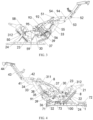
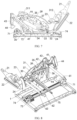
- the stretching assembly includes backrest units 2, seat frame units 3 and leg stretching units 4 which are disposed symmetrically disposed at two sides of the base 1 in a width direction (a W direction shown in FIG. 2 ) of the base 1, front and rear ends of the seat frame unit 3 are hinged to one end of the backrest unit 2 and one end of the leg stretching unit 4 respectively.
- the front and rear ends of the seat frame unit 3 refer to both ends of the seat frame unit 3 in an L direction (a length direction) shown in FIG. 2 .
- the front end of the seat frame unit 3 refers to an end at which the leg stretching unit 4 is located, and the rear end of the seat frame unit 3 refers to an end at which of the backrest unit 2 is located.
- An H direction shown in FIG. 2 is a height direction.
- the driving assembly connects two seat frame units 3 through a connection unit, enabling the two stretching assemblies to be stretched and retracted synchronously along the length direction such that the stretching assembly switches between a sitting position state, a television (TV) position state and a lying position state.
- a connection unit enabling the two stretching assemblies to be stretched and retracted synchronously along the length direction such that the stretching assembly switches between a sitting position state, a television (TV) position state and a lying position state.
- the structure of the base 1 is described below.
- the base 1 includes two front-rear connectors 11 and two left-right connectors 12, the two front-rear connectors 11 and the two left-right connectors 12 are connected by fasteners such as bolts to form one rectangular frame, and the base 1 serves as a support for supporting structural members connected to the base 1.
- one rectangular frame may also be formed by welding two front-rear connectors 11 and two left-right connectors 12.
- the second leg rest plate connector 42 is provided with a fourth stopper member 94 for stopping an upper end surface of the first leg rest plate connector 41.
- the first hinge point 51, the fourth stopper member 94, the third hinge point 53, and the second hinge point 52 are distributed sequentially in an extending direction of the second leg rest plate connector 42.
- the seat frame unit 3 includes a seat frame support 31, a first support 32, a second support 33, and a third support 34.
- the two seat frame units 3 are connected by a drive connecting rod 75.
- Two axial ends of the drive connecting rod 75 pass through the two seat frame units 3 and are fixedly connected to one end of the two first supports 32 so that the first support 32 is rotatable relative to the seat frame support 31.
- the other end of the first support 32 is hinged to one end of the second support 33, the other end of the second support 33 is hinged to the middle of the second leg rest plate connector 42 at a fourth hinge point 54, one end of the second leg rest plate connector 42 facing away from the third leg rest plate connector 43 is hinged to the seat frame support 31 at the first hinge point 51, and the fourth hinge point 54 is located between the first hinge point 51 and the fourth stopper member 94.
- One end of the third support 34 is hinged to one end of the first leg rest plate connector 41, and the other end of the third support 34 is hinged to the seat frame support 31 at the fifth hinge point 55.
- the seat frame unit 3 further includes a first connector 35, a second connector 36, a third connector 37, a fourth connector 38, a fifth connector 39 and a sixth connector 30.
- One end of the first connector 35 is hinged to the seat frame support 31 at a sixth hinge point 56, a middle of the first connector 35 is hinged to one end of the third connector 37, the other end of the first connector 35 is hinged to one end of the second connector 36, and the other end of the second connector 36 is hinged to a front end of the left-right connector 12; and the other end of the third connector 37 is hinged to the backrest unit 2.
- one end of the fourth connector 38 is hinged to a middle of the third support 34, the other end of the fourth connector 38 is hinged to one end of the sixth connector 30, a middle of the sixth connector 30 is hinged to the seat frame support 31 at a seventh hinge point 57, the other end of the sixth connector 30 is hinged to one end of the fifth connector 39, and the other end of the fifth connector 39 is hinged to the middle of the second connector 36.
- the backrest unit 2 includes a first backrest connector 21, a second backrest connector 22, a third backrest connector 23, and a fourth backrest connector 24.
- One end of a lower part of the first backrest connector 21 is hinged to one end of the second backrest connector 22, the other end of the lower part of the first backrest connector 21 is hinged to the seat frame support 31 at an eighth hinge point 58
- the third backrest connector 23 is in a substantially V-shaped structure
- one end portion of the third backrest connector 23 is hinged to the other end of the second backrest connector 22
- a middle of the third backrest connector 23 is hinged to one end of the third connector 37
- the other end portion of the third backrest connector 23 is hinged to one end of the fourth backrest connector 24 at a tenth hinge point 50
- the third backrest connector 23 is hinged to the seat frame support 31 at a ninth hinge point 59
- the ninth hinge point 59 is located between the other end of the third backrest connector 23 and the middle of the third backrest connector 23, the
- the seat frame support 31 includes a first seat frame member 311 and a second seat frame member 312, a lower end of the first seat frame member 311 and a lower end of the second seat frame member 312 are connected to form the seat frame support 31 which is in a shape of " ⁇ ".
- the first hinge point 51, the fifth hinge point 55, the sixth hinge point 56 are located on the first seat frame member 311, and are distributed in a direction from the first seat frame member 311 to the second seat frame member 312 sequentially, the eighth hinge point 58 is located at a free end of the second seat frame member 312, the ninth hinge point 59 is located at a connection position of the first seat frame member 311 and the second seat frame member 312, that is, at a turning position of the " ⁇ "-shaped structure.
- the other end of the backrest spring 100 is connected to a middle position of the second seat frame member 312.
- an included angle between a surface of the third support 34 facing a lateral surface of the base 1 when the two stretching assemblies are in the sitting position state, and a rear lateral surface of the third support 34 when the two stretching assemblies are in the lying position state is A; and the tenth hinge point 50 is always located below the middle position of the second seat frame member 312 during the stretching or retracting process of the two stretching assemblies such that 100° ⁇ A ⁇ 110°.
- A may be 100°, 101°, 102°, 103°, 104°, 105°, 106°, 107°, 108°, 109° and 110°.
- A 106°.
- a position of the tenth hinge point 50 is limited, a magnitude of A is adjusted so that the position of the tenth hinge point 50 is much lower, that is, a stretching distance of the third backrest connector 23 and the fourth backrest connector 24 is shorter, the smoothness of the stretching or retracting of the stretching assembly is improved so that when the stretching assembly is in the lying position, the zero-gravity feeling of the user lying on the sofa seat is obvious.
- the stretching assembly can remain in the TV position state.
- the linear drive unit 71 continues to drive the sliding block 73 toward the side of the leg stretching unit 4, the first connector 35 moves downward, disengages the stopping action of the second stopper member 92 and moves to a position where the first connector 35 comes into contact with the third stopper member 93, the third stopper member 93 is fully clamped to the lower lateral surface of the first connector 35, in this case, the stretching assembly reaches a stable lying position state.
- the stretching assembly is retracted, the stretching assembly can sequentially move in reverse.
- one end of the second support 33 facing away from the first support 32 is hinged to the middle of the third support
- one end of the second support 33 facing away from the first support 32 is hinged to the second leg rest connector 42 at the fourth hinge point 54, so that when the sliding block moves a same distance, the stretching assembly's stretching speed is reduced in a process of switching from a sitting position state to a lying position state. Reducing the switching speed of switching from the sitting position state to the lying position state can effectively avoid the weightlessness.
- the driving assembly drives the stretching assembly to act so that the process of switching the stretching assembly from the lying position state to the sitting position state is smoother.
- a backrest spring 100 has a telescopic length of a1 when the stretching assembly is in the sitting position state and the TV position state, and the backrest spring 100 has a telescopic length of a2 when the stretching assembly is in the lying position state, and a ratio of a1 to a2 ranges from 0.7 to 0.9.
- a length of the backrest spring 100 is 105.22 mm.
- the backrest spring 100 When the stretching assembly is stretched to the lying position state, the backrest spring 100 is stretched to a maximum length, in this case, the length is 125.02 mm.
- the stretching assembly is retracted, the backrest unit 2 is rotated back first, and then the leg stretching unit 4 is retracted.
- a contractile force of the backrest spring 100 makes the retracting process natural and smooth, and the retracting process is much easier.
- two seat frame mounting members 8 are arranged on an outer side of the seat frame support 31 for mounting a cushion.
- one seat frame mounting member 8 is disposed on each of an outer side of the first seat frame member 311 and an outer side of the second seat frame member 312; and angles between lower lateral surfaces of the two seat frame mounting members 8 on a same seat frame support 31 and the base 1 are B1 and B2 respectively, referring to FIG. 4 , when the two stretching assembly is in the lying position state, values of B1 and B2 range from 13° to 23°.
- the stretching assembly conforms to the ergonomic structure, so that the lying position is flatter and reaches a posture of zero gravity of the human body, that is, the stretching assembly is more comfortable.
- one end of the second support facing away from the first support is hinged to the middle of the third support
- one end of the second support facing away from the first support is hinged to the second leg rest plate connector at the fourth hinge point, so that the stretching assembly's stretching speed is reduced in the process of switching from the sitting position state to the lying position state when the driving assembly acts in the same way, and the weightlessness feeling can be effectively avoided.
- the driving assembly drives the stretching assembly to act so that the process of switching the stretching assembly from the lying position state to the sitting position state is smoother.
- the fourth stopper member 94 functions as a stopper for the first leg rest plate connector 41 to improve the stability of the stretching assembly in different states.
- the third stopper member 93 is clamped on the lower lateral surface of the first connector 35 to support and stop the first connector 35, so that the stretching assembly stably remains in the lying position state.
- a direction in which a leg (or the leg stretching unit 4) extends outward may be defined as a front (the front end), and a direction in which a backrest (or the backrest unit 2) extends may be defined as a rear (the rear end).
- a direction between the leg (or the leg stretching unit 4) and the backrest (or the backrest unit 2) may be defined as a length direction (the L direction, the front-back direction)
- a direction horizontally perpendicular to the front-back direction may be defined as a width direction (the W direction) of the base 1
- a direction perpendicular to the L direction and the W direction may be defined as a height direction (an H direction).
Landscapes
- Health & Medical Sciences (AREA)
- General Health & Medical Sciences (AREA)
- Dentistry (AREA)
- Nursing (AREA)
- Chairs For Special Purposes, Such As Reclining Chairs (AREA)
Claims (12)
- Sofasitz-Streckvorrichtung, umfassend eine Basis (1), zwei Streckanordnungen und eine Antriebsanordnung, wobei die zwei Streckanordnungen und die Antriebsanordnung auf der Basis (1) angeordnet sind,wobei die zwei Streckanordnungen zwei Rückenlehnen-Einheiten (2), zwei Sitzrahmen-Einheiten (3) und zwei Beinstreckeinheiten (4) umfassen, wobei die zwei Rückenlehnen-Einheiten (2), die zwei Sitzrahmen-Einheiten (3) und die zwei Beinstreckeinheiten (4) symmetrisch an beiden Enden der Basis (1) in einer Breitenrichtung der Basis (1) angeordnet sind, wobei zwei Enden jeder der zwei Sitzrahmen-Einheiten (3) an einem Ende einer Rückenlehnen-Einheit (2) der zwei Rückenlehnen-Einheiten (2) und an einem Ende einer Beinstreckeinheit (4) der zwei Beinstreckeinheiten (4) jeweils angelenkt sind;wobei die Antriebsanordnung konfiguriert ist, um die zwei Streckanordnungen zum synchronen Ein- oder Ausfahren in einer Längsrichtung der zwei Streckanordnungen anzutreiben, so dass die zwei Streckanordnungen zwischen einem Sitzpositionzustand, einem TV-Positionzustand und einem Liegepositionzustand wechseln, wobei jede der zwei Beinstreckeinheiten (4) einen ersten Beinauflagen-Verbinder (41) und einen zweiten Beinauflagen-Verbinder (42) umfasst, wobei eine Mitte des ersten Beinauflagen-Verbinders (41) und eine Mitte des zweiten Beinauflagen-Verbinders (42) an einem dritten Gelenkpunkt angelenkt sind;wobei die Sofasitz-Streckvorrichtung dadurch gekennzeichnet ist, dass jede der zwei Sitzrahmen-Einheiten (3) einen Sitzrahmen-Träger (31), einen ersten Träger (32), einen zweiten Träger (33) und einen dritten Träger (34) umfasst, wobei der Sitzrahmen-Träger (31) an einem ersten Gelenkpunkt (51) an einem Ende des zweiten Beinauflagen-Verbinders (42) angelenkt ist, wobei der erste Träger (32), der zweite Träger (33) und der dritte Träger (34) jeweils relativ zum Sitzrahmen-Träger (31) drehbar sind, wobei ein Ende des dritten Trägers (34) an einem fünften Gelenkpunkt (55) am Sitzrahmen-Träger (31) angelenkt ist, während das andere Ende des dritten Trägers (34) am ersten Beinauflagen-Verbinder (41) angelenkt ist, wobei ein Ende des zweiten Trägers (33) an einem Ende des ersten Trägers (32) angelenkt und das andere Ende des zweiten Trägers (33) am zweiten Beinauflagen-Verbinder (42) an einem vierten Gelenkpunkt (54) angelenkt ist, wobei der vierte Gelenkpunkt (54) zwischen dem ersten Gelenkpunkt (51) und dem dritten Gelenkpunkt (53) liegt und der erste Gelenkpunkt (51) vor dem fünften Gelenkpunkt (55) liegt;wobei jede der zwei Sitzrahmen-Einheiten (3) weiterhin einen ersten Verbinder (35), einen zweiten Verbinder (36), einen dritten Verbinder (37), einen vierten Verbinder (38), einen fünften Verbinder (39) und einen sechsten Verbinder (30) umfasst;wobei ein Ende des ersten Verbinders (35) am Sitzrahmen-Träger (31) angelenkt, eine Mitte des ersten Verbinders (35) an einem Ende des dritten Verbinders (37) angelenkt, das andere Ende des ersten Verbinders (35) an einem Ende des zweiten Verbinders (36) angelenkt, und das andere Ende des zweiten Verbinders (36) an einem vorderen Ende der Basis (1) angelenkt ist; wobei das andere Ende des dritten Verbinders (37) an einer der zwei Rückenlehnen-Einheiten (2) angelenkt ist;wobei ein Ende des vierten Verbinders (38) an einer Mitte des dritten Trägers (34) angelenkt ist, während das andere Ende des vierten Verbinders (38) an einem Ende des sechsten Verbinders (30) angelenkt ist; wobei eine Mitte des sechsten Verbinders (30) am Sitzrahmen-Träger (31) angelenkt, das andere Ende des sechsten Verbinders (30) an einem Ende des fünften Verbinders (39) angelenkt, und das andere Ende des fünften Verbinders (39) an der Mitte des zweiten Verbinders (36) angelenkt ist;wobei der erste Verbinder (35) mit einem ersten Anschlagelement (91) versehen ist, um eine Bewegung des dritten Trägers (34) zu stoppen, wobei der Sitzrahmen-Träger (31) mit einem zweiten Anschlagelement (92), um ein Zurückziehen jeder der zwei Streckanordnungen zu stoppen, und einem dritten Anschlagelement (93) versehen ist, um ein Ausfahren jeder der zwei Streckanordnungen zu stoppen, wobei das zweite Anschlagelement (92) und das dritte Anschlagelement (93) an zwei Seiten des ersten Verbinders (35) angeordnet sind;wobei, wenn die zwei Streckanordnungen in einem Liegepositionzustand sind, das dritte Anschlagelement (93) am ersten Verbinder (35) anliegt;wobei, wenn die zwei Streckanordnungen in einem Sitzpositionzustand sind, das zweite Anschlagelement (92) am ersten Verbinder (35) anliegt und das erste Anschlagelement (91) zwischen dem Sitzrahmen-Träger (31) und dem dritten Träger (34) eingeklemmt ist; undwobei der zweite Beinauflagen-Verbinder (42) mit einem vierten Anschlagelement (94) versehen ist, um eine obere Endfläche des ersten Beinauflagen-Verbinders (41) zu stoppen.
- Sofasitz-Streckvorrichtung nach Anspruch 1, wobei jede der zwei Rückenlehnen-Einheiten (2) einen ersten Rückenlehnenverbinder (21), einen zweiten Rückenlehnenverbinder (22), einen dritten Rückenlehnenverbinder (23) und einen vierten Rückenlehnenverbinder (24) umfasst; und
wobei ein Ende eines unteren Teils des ersten Rückenlehnenverbinders (21) an einem Ende des zweiten Rückenlehnenverbinders (22) gelenkig gelagert, und das andere Ende des unteren Teils des ersten Rückenlehnenverbinders (21) am Sitzrahmenträger (31) gelenkig gelagert ist; wobei ein Endabschnitt des dritten Rückenlehnenverbinders (23) am anderen Ende des zweiten Rückenlehnenverbinders (22) gelenkig gelagert, die Mitte des dritten Rückenlehnenverbinders (23) an einem Ende des dritten Verbinders (37) gelenkig gelagert, der andere Endabschnitt des dritten Rückenlehnenverbinders (23) an einem Ende des vierten Rückenlehnenverbinders (24) an einem zehnten Gelenkpunkt (50) gelenkig gelagert, der dritte Rückenlehnenverbinder (23) am Sitzrahmenträger (31) gelenkig gelagert, und das andere Ende des vierten Rückenlehnenverbinders (24) an einem hinteren Ende der Basis (1) gelenkig gelagert ist. - Sofasitz-Streckvorrichtung nach Anspruch 2, wobei der dritte Rückenlehnenverbinder (23) durch eine Rückenlehnenfeder (100) mit dem Sitzrahmenträger (31) verbunden ist, wobei die Rückenlehnenfeder (100) eine Auszugslänge von a1 aufweist, wenn sich die beiden Streckanordnungen in einem Sitzpositionzustand und einem TV-Positionzustand befinden, und die Rückenlehnenfeder (100) eine Auszugslänge von a2 aufweist, wenn sich die beiden Streckanordnungen in einem Liegepositionzustand befinden, und wobei ein Verhältnis von a1 zu a2 im Bereich von 0,7 bis 0,9 liegt.
- Sofasitz-Streckvorrichtung nach Anspruch 3, wobei der Sitzrahmenträger (31) ein erstes Sitzrahmenelement (311), dessen eines Ende mit jeder der beiden Beinstreckeinheiten (4) verbunden ist, und ein zweites Sitzrahmenelement (312), dessen eines Ende mit jeder der beiden Rückenlehnen-Einheiten (2) verbunden ist, umfasst, wobei das andere Ende des ersten Sitzrahmenelements (311) mit dem anderen Ende des zweiten Sitzrahmenelements (312) verbunden ist, um den Sitzrahmenträger (31) zu bilden, der eine L-Form aufweist; wobei ein Ende der Rückenlehnenfeder (100) mit dem dritten Rückenlehnenverbinder (23) verbunden ist, während das andere Ende der Rückenlehnenfeder (100) mit einer Mittelposition des zweiten Sitzrahmenelements (312) verbunden ist.
- Sofasitz-Streckvorrichtung nach Anspruch 4, wobei ein eingeschlossener Winkel zwischen einer Oberfläche des dritten Trägers (34), die einer Seitenfläche der Basis (1) zugewandt ist, wenn sich die beiden Streckanordnungen im Sitzpositionzustand befinden, und einer hinteren Seitenfläche des dritten Trägers (34), wenn sich die beiden Streckanordnungen im Liegepositionzustand befinden, A beträgt; und
wobei der zehnte Gelenkpunkt (50) während des Ausfahr- oder Einfahrvorgangs der beiden Streckanordnungen stets unterhalb der Mittelposition des zweiten Sitzrahmenelements (312) angeordnet ist, so dass 100° ≤ A ≤ 110° gilt. - Sofasitz-Streckvorrichtung nach Anspruch 4, wobei zwei Sitzrahmen-Befestigungselemente (8) jeweils an einer Außenseite des ersten Sitzrahmenelements (311) und einer Außenseite des zweiten Sitzrahmenelements (312) angeordnet sind; und
Winkel zwischen unteren Seitenflächen der beiden Sitzrahmen-Befestigungselemente (8) auf demselben Sitzrahmenträger (31) und der Basis (1) B1 und B2 betragen, wenn sich die beiden Streckanordnungen im Liegepositionzustand befinden, wobei die Werte von B1 und B2 im Bereich von 13° bis 23° liegen. - Sofasitz-Streckvorrichtung nach Anspruch 2, wobei ein sechster Verbinder (30) mit einem fünften Anschlagelement (95) versehen ist, das Bewegungen des dritten Verbinders (37) und des dritten Rückenlehnenverbinders (23) begrenzt; und
wobei, wenn sich die beiden Streckanordnungen im Sitzpositionzustand befinden, das fünfte Anschlagelement (95) an einer oberen Seitenfläche des dritten Verbinders (37) und einer oberen Seitenfläche des dritten Rückenlehnenverbinders (23) anliegt. - Sofasitz-Streckvorrichtung nach Anspruch 7, wobei jedes der zweiten Anschlagelemente (92) und dritten Anschlagelemente (93) als V-förmiger Anschlagvorsprung ausgebildet ist, und wobei der V-förmige Anschlagvorsprung einstückig mit dem Sitzrahmenträger (31) geformt ist; und
wobei das vierte Anschlagelement (94), das erste Anschlagelement (91) und das fünfte Anschlagelement (95) alle in einer säulenförmigen Struktur angeordnet sind. - Sofasitz-Streckvorrichtung nach einem der Ansprüche 1 bis 8, wobei die Antriebsanordnung eine Führungsschiene (72) und eine Linearantriebseinheit (71) umfasst, die auf der Basis (1) befestigt sind,wobei die Führungsschiene (72) mit einem Schlitten (73) versehen ist, der in einer Vorne-Hinten-Richtung gleitend mit der Führungsschiene (72) verbunden ist, und wobei der Schlitten (73) über eine Verbindungseinheit mit dem dritten Träger (34) der beiden Sitzrahmeneinheiten (3) verbunden ist; undwobei eine Linearantriebseinheit (71) vorgesehen ist, die auf der Basis (1) befestigt ist, wobei ein Ausgangselement der Linearantriebseinheit (71) fest mit dem Schlitten (73) verbunden ist.
- Sofasitz-Streckvorrichtung nach einem der Ansprüche 1 bis 8, wobei der erste Gelenkpunkt (51), der vierte Gelenkpunkt (54), das vierte Anschlagelement (94) und der dritte Gelenkpunkt (53) in dieser Reihenfolge in einer Erstreckungsrichtung des zweiten Beinauflagenverbinders (42) angeordnet sind.
- Sofasitz-Streckvorrichtung nach Anspruch 7, wobei das zweite Anschlagelement (92) und das dritte Anschlagelement (93) jeweils als V-förmige Anschlagvorsprünge ausgebildet sind, und wobei die V-förmigen Anschlagvorsprünge einstückig mit dem Sitzrahmenträger (31) geformt sind.
- Sofasitz-Streckvorrichtung nach Anspruch 7, wobei das vierte Anschlagelement (94), das erste Anschlagelement (91) und das fünfte Anschlagelement (95) alle in der säulenförmigen Struktur ausgebildet sind.
Applications Claiming Priority (3)
| Application Number | Priority Date | Filing Date | Title |
|---|---|---|---|
| CN202122414443.3U CN215738007U (zh) | 2021-10-08 | 2021-10-08 | 一种沙发座椅伸展装置 |
| CN202111170623.XA CN113749460B (zh) | 2021-10-08 | 2021-10-08 | 一种沙发座椅伸展装置 |
| PCT/CN2021/130788 WO2023056686A1 (zh) | 2021-10-08 | 2021-11-16 | 沙发座椅伸展装置 |
Publications (3)
| Publication Number | Publication Date |
|---|---|
| EP4183295A1 EP4183295A1 (de) | 2023-05-24 |
| EP4183295A4 EP4183295A4 (de) | 2024-03-20 |
| EP4183295B1 true EP4183295B1 (de) | 2025-07-09 |
Family
ID=85800339
Family Applications (1)
| Application Number | Title | Priority Date | Filing Date |
|---|---|---|---|
| EP21881351.7A Active EP4183295B1 (de) | 2021-10-08 | 2021-11-16 | Streckvorrichtung für sofasitz |
Country Status (3)
| Country | Link |
|---|---|
| US (1) | US12207731B2 (de) |
| EP (1) | EP4183295B1 (de) |
| WO (1) | WO2023056686A1 (de) |
Families Citing this family (12)
| Publication number | Priority date | Publication date | Assignee | Title |
|---|---|---|---|---|
| WO2023020514A1 (zh) * | 2021-08-17 | 2023-02-23 | 德沃康科技集团有限公司 | 机械伸展装置及其悬挂机构 |
| CN216256324U (zh) * | 2021-12-08 | 2022-04-12 | 德沃康科技集团有限公司 | 一种多状态切换的沙发座椅 |
| US20240315452A1 (en) * | 2023-03-23 | 2024-09-26 | L&P Property Management Company | High-leg recliner seating mechanism |
| US20240315453A1 (en) * | 2023-03-23 | 2024-09-26 | L&P Property Management Company | High-leg recliner seating mechanism |
| US20240336167A1 (en) * | 2023-04-06 | 2024-10-10 | Camaco, LLC | Constant center lounge seat |
| CN220001288U (zh) * | 2023-05-08 | 2023-11-14 | 海宁和力机械科技有限公司 | 座椅骨架及可切换坐卧姿态的座椅 |
| CN220212407U (zh) * | 2023-06-25 | 2023-12-22 | 浙江飞力科技有限公司 | 一种提供零重力姿态的座椅伸展装置 |
| CN220800549U (zh) * | 2023-08-28 | 2024-04-19 | 一么么科技(浙江)有限公司 | 电动机械伸展装置 |
| CN117582088A (zh) * | 2023-11-27 | 2024-02-23 | 飞适汽车配件(嘉善)有限公司 | 一种沙发调节总成 |
| KR20250089663A (ko) * | 2023-12-12 | 2025-06-19 | 현대자동차주식회사 | 회전 메커니즘 및 이를 포함하는 시트 |
| US20250288116A1 (en) * | 2024-03-14 | 2025-09-18 | Nine Wood Trading Co., Limited | Adjustable sofa |
| MX2024004286A (es) * | 2024-04-05 | 2024-08-08 | Ind Nortecaucanas S A S | Sillon reclinable con mecanismo de reclinacion y ensamblaje de mecanismo de reclinacion para gradas de recintos. |
Family Cites Families (10)
| Publication number | Priority date | Publication date | Assignee | Title |
|---|---|---|---|---|
| US5103510A (en) * | 1991-01-18 | 1992-04-14 | Flexsteel Industries, Inc. | Locking linkage for sofa bed |
| CN202932424U (zh) * | 2012-11-12 | 2013-05-15 | 常州市锐新医疗器械有限公司 | 多连杆伸展机构 |
| CN108260984A (zh) * | 2018-01-16 | 2018-07-10 | 锐迈机械科技(吴江)有限公司 | 一种功能沙发机械伸展装置 |
| CN212036846U (zh) | 2020-04-26 | 2020-12-01 | 德沃康科技集团有限公司 | 一种智能沙发机械伸展装置 |
| CN212521294U (zh) * | 2020-06-13 | 2021-02-12 | 德沃康科技集团有限公司 | 一种搁腿板组件及智能沙发机械伸展装置 |
| CN213909383U (zh) * | 2020-11-28 | 2021-08-10 | 顾家家居股份有限公司 | 一种搁脚可折叠的功能沙发机械伸展装置 |
| CN112716194B (zh) * | 2021-01-18 | 2024-11-26 | 德沃康科技集团有限公司 | 一种沙发伸展装置 |
| CN113261806A (zh) * | 2021-05-21 | 2021-08-17 | 浙江米檬家居科技有限公司 | 一种支撑性好的功能沙发伸展装置 |
| CN113317651B (zh) * | 2021-07-09 | 2025-02-21 | 德沃康科技集团有限公司 | 座椅伸展支架、座椅伸展装置及座椅 |
| US11564498B1 (en) * | 2021-08-30 | 2023-01-31 | Dewertokin Technology Group Co., Ltd. | Intelligent sofa mechanical extension device |
-
2021
- 2021-11-16 WO PCT/CN2021/130788 patent/WO2023056686A1/zh not_active Ceased
- 2021-11-16 EP EP21881351.7A patent/EP4183295B1/de active Active
- 2021-11-16 US US17/770,847 patent/US12207731B2/en active Active
Also Published As
| Publication number | Publication date |
|---|---|
| US20240138577A1 (en) | 2024-05-02 |
| EP4183295A1 (de) | 2023-05-24 |
| US12207731B2 (en) | 2025-01-28 |
| EP4183295A4 (de) | 2024-03-20 |
| WO2023056686A1 (zh) | 2023-04-13 |
Similar Documents
| Publication | Publication Date | Title |
|---|---|---|
| EP4183295B1 (de) | Streckvorrichtung für sofasitz | |
| EP4173521A1 (de) | Mechanische streckvorrichtung für bewegliche sitzeinheit und sitzeinheit | |
| US11564498B1 (en) | Intelligent sofa mechanical extension device | |
| EP3860403B1 (de) | Neigungsverstellbare sitzeinheit mit wandnäherungskapazität | |
| CN111820648B (zh) | 一种高抬腿座椅机构及座椅 | |
| US20250228368A1 (en) | Chair | |
| US12520941B1 (en) | Seat bracket and zero-wall-gap seat with seat bracket | |
| CN111839052B (zh) | 一种电动机械伸展装置 | |
| US20250338963A1 (en) | Mechanical stretching device for movable seat unit and seat unit | |
| CN213640252U (zh) | 一种座椅联动支架结构 | |
| US20260047680A1 (en) | Seat bracket and zero-wall-gap seat with seat bracket | |
| CN108523495B (zh) | 一种多位姿调节座椅 | |
| US12369714B2 (en) | Chair | |
| CN113749460B (zh) | 一种沙发座椅伸展装置 | |
| CN222777131U (zh) | 可活动的座椅单元及其机械伸展装置 | |
| CN222675784U (zh) | 用于可活动的座椅单元的机械伸展装置及座椅单元 | |
| CN215738007U (zh) | 一种沙发座椅伸展装置 | |
| CN220458963U (zh) | 一种座椅支架及座椅单元 | |
| CN220458964U (zh) | 一种座椅单元及座椅 | |
| CN220876338U (zh) | 用于可活动座椅的机械伸展装置和可活动的座椅单元 | |
| CN114009999B (zh) | 一种滑动翻转机构、头枕调节装置及头枕支架 | |
| WO2023087862A1 (zh) | 一种翻转调节机构、头枕翻转装置及头枕支架 | |
| EP4696196A1 (de) | Sitzbeschlag und sitz mit dem sitzbeschlag | |
| US20250049220A1 (en) | Extendable seat frame and furniture thereof | |
| CN223473389U (zh) | 头枕和人体工学椅 |
Legal Events
| Date | Code | Title | Description |
|---|---|---|---|
| STAA | Information on the status of an ep patent application or granted ep patent |
Free format text: STATUS: UNKNOWN |
|
| STAA | Information on the status of an ep patent application or granted ep patent |
Free format text: STATUS: THE INTERNATIONAL PUBLICATION HAS BEEN MADE |
|
| PUAI | Public reference made under article 153(3) epc to a published international application that has entered the european phase |
Free format text: ORIGINAL CODE: 0009012 |
|
| STAA | Information on the status of an ep patent application or granted ep patent |
Free format text: STATUS: REQUEST FOR EXAMINATION WAS MADE |
|
| 17P | Request for examination filed |
Effective date: 20220428 |
|
| AK | Designated contracting states |
Kind code of ref document: A1 Designated state(s): AL AT BE BG CH CY CZ DE DK EE ES FI FR GB GR HR HU IE IS IT LI LT LU LV MC MK MT NL NO PL PT RO RS SE SI SK SM TR |
|
| A4 | Supplementary search report drawn up and despatched |
Effective date: 20240215 |
|
| RIC1 | Information provided on ipc code assigned before grant |
Ipc: A47C 1/032 20060101ALI20240209BHEP Ipc: A47C 1/0355 20130101ALI20240209BHEP Ipc: A47C 17/86 20060101AFI20240209BHEP |
|
| RIN1 | Information on inventor provided before grant (corrected) |
Inventor name: TU, HANHAO Inventor name: TAO, KANGMING Inventor name: SHEN, BIN Inventor name: YE, QIQI Inventor name: YANG, LIMING |
|
| DAV | Request for validation of the european patent (deleted) | ||
| DAX | Request for extension of the european patent (deleted) | ||
| GRAP | Despatch of communication of intention to grant a patent |
Free format text: ORIGINAL CODE: EPIDOSNIGR1 |
|
| STAA | Information on the status of an ep patent application or granted ep patent |
Free format text: STATUS: GRANT OF PATENT IS INTENDED |
|
| INTG | Intention to grant announced |
Effective date: 20250404 |
|
| GRAS | Grant fee paid |
Free format text: ORIGINAL CODE: EPIDOSNIGR3 |
|
| GRAA | (expected) grant |
Free format text: ORIGINAL CODE: 0009210 |
|
| STAA | Information on the status of an ep patent application or granted ep patent |
Free format text: STATUS: THE PATENT HAS BEEN GRANTED |
|
| AK | Designated contracting states |
Kind code of ref document: B1 Designated state(s): AL AT BE BG CH CY CZ DE DK EE ES FI FR GB GR HR HU IE IS IT LI LT LU LV MC MK MT NL NO PL PT RO RS SE SI SK SM TR |
|
| REG | Reference to a national code |
Ref country code: GB Ref legal event code: FG4D |
|
| REG | Reference to a national code |
Ref country code: CH Ref legal event code: EP |
|
| REG | Reference to a national code |
Ref country code: IE Ref legal event code: FG4D |
|
| REG | Reference to a national code |
Ref country code: DE Ref legal event code: R096 Ref document number: 602021033967 Country of ref document: DE |
|
| REG | Reference to a national code |
Ref country code: NL Ref legal event code: MP Effective date: 20250709 |
|
| PG25 | Lapsed in a contracting state [announced via postgrant information from national office to epo] |
Ref country code: PT Free format text: LAPSE BECAUSE OF FAILURE TO SUBMIT A TRANSLATION OF THE DESCRIPTION OR TO PAY THE FEE WITHIN THE PRESCRIBED TIME-LIMIT Effective date: 20251110 |
|
| PG25 | Lapsed in a contracting state [announced via postgrant information from national office to epo] |
Ref country code: NL Free format text: LAPSE BECAUSE OF FAILURE TO SUBMIT A TRANSLATION OF THE DESCRIPTION OR TO PAY THE FEE WITHIN THE PRESCRIBED TIME-LIMIT Effective date: 20250709 |
|
| REG | Reference to a national code |
Ref country code: AT Ref legal event code: MK05 Ref document number: 1810987 Country of ref document: AT Kind code of ref document: T Effective date: 20250709 |
|
| PG25 | Lapsed in a contracting state [announced via postgrant information from national office to epo] |
Ref country code: IS Free format text: LAPSE BECAUSE OF FAILURE TO SUBMIT A TRANSLATION OF THE DESCRIPTION OR TO PAY THE FEE WITHIN THE PRESCRIBED TIME-LIMIT Effective date: 20251109 |
|
| PGFP | Annual fee paid to national office [announced via postgrant information from national office to epo] |
Ref country code: DE Payment date: 20251117 Year of fee payment: 5 |
|
| PG25 | Lapsed in a contracting state [announced via postgrant information from national office to epo] |
Ref country code: NO Free format text: LAPSE BECAUSE OF FAILURE TO SUBMIT A TRANSLATION OF THE DESCRIPTION OR TO PAY THE FEE WITHIN THE PRESCRIBED TIME-LIMIT Effective date: 20251009 |
|
| REG | Reference to a national code |
Ref country code: LT Ref legal event code: MG9D |
|
| PG25 | Lapsed in a contracting state [announced via postgrant information from national office to epo] |
Ref country code: AT Free format text: LAPSE BECAUSE OF FAILURE TO SUBMIT A TRANSLATION OF THE DESCRIPTION OR TO PAY THE FEE WITHIN THE PRESCRIBED TIME-LIMIT Effective date: 20250709 |
|
| PG25 | Lapsed in a contracting state [announced via postgrant information from national office to epo] |
Ref country code: FI Free format text: LAPSE BECAUSE OF FAILURE TO SUBMIT A TRANSLATION OF THE DESCRIPTION OR TO PAY THE FEE WITHIN THE PRESCRIBED TIME-LIMIT Effective date: 20250709 |
|
| PGFP | Annual fee paid to national office [announced via postgrant information from national office to epo] |
Ref country code: IT Payment date: 20251107 Year of fee payment: 5 |
|
| PG25 | Lapsed in a contracting state [announced via postgrant information from national office to epo] |
Ref country code: HR Free format text: LAPSE BECAUSE OF FAILURE TO SUBMIT A TRANSLATION OF THE DESCRIPTION OR TO PAY THE FEE WITHIN THE PRESCRIBED TIME-LIMIT Effective date: 20250709 |
|
| PG25 | Lapsed in a contracting state [announced via postgrant information from national office to epo] |
Ref country code: GR Free format text: LAPSE BECAUSE OF FAILURE TO SUBMIT A TRANSLATION OF THE DESCRIPTION OR TO PAY THE FEE WITHIN THE PRESCRIBED TIME-LIMIT Effective date: 20251010 |
|
| PG25 | Lapsed in a contracting state [announced via postgrant information from national office to epo] |
Ref country code: SE Free format text: LAPSE BECAUSE OF FAILURE TO SUBMIT A TRANSLATION OF THE DESCRIPTION OR TO PAY THE FEE WITHIN THE PRESCRIBED TIME-LIMIT Effective date: 20250709 |
|
| PG25 | Lapsed in a contracting state [announced via postgrant information from national office to epo] |
Ref country code: LV Free format text: LAPSE BECAUSE OF FAILURE TO SUBMIT A TRANSLATION OF THE DESCRIPTION OR TO PAY THE FEE WITHIN THE PRESCRIBED TIME-LIMIT Effective date: 20250709 |
|
| PG25 | Lapsed in a contracting state [announced via postgrant information from national office to epo] |
Ref country code: BG Free format text: LAPSE BECAUSE OF FAILURE TO SUBMIT A TRANSLATION OF THE DESCRIPTION OR TO PAY THE FEE WITHIN THE PRESCRIBED TIME-LIMIT Effective date: 20250709 Ref country code: PL Free format text: LAPSE BECAUSE OF FAILURE TO SUBMIT A TRANSLATION OF THE DESCRIPTION OR TO PAY THE FEE WITHIN THE PRESCRIBED TIME-LIMIT Effective date: 20250709 |
|
| PG25 | Lapsed in a contracting state [announced via postgrant information from national office to epo] |
Ref country code: RS Free format text: LAPSE BECAUSE OF FAILURE TO SUBMIT A TRANSLATION OF THE DESCRIPTION OR TO PAY THE FEE WITHIN THE PRESCRIBED TIME-LIMIT Effective date: 20251009 |
|
| PG25 | Lapsed in a contracting state [announced via postgrant information from national office to epo] |
Ref country code: ES Free format text: LAPSE BECAUSE OF FAILURE TO SUBMIT A TRANSLATION OF THE DESCRIPTION OR TO PAY THE FEE WITHIN THE PRESCRIBED TIME-LIMIT Effective date: 20250709 |
|
| PG25 | Lapsed in a contracting state [announced via postgrant information from national office to epo] |
Ref country code: RO Free format text: LAPSE BECAUSE OF FAILURE TO SUBMIT A TRANSLATION OF THE DESCRIPTION OR TO PAY THE FEE WITHIN THE PRESCRIBED TIME-LIMIT Effective date: 20250709 |
|
| PG25 | Lapsed in a contracting state [announced via postgrant information from national office to epo] |
Ref country code: SM Free format text: LAPSE BECAUSE OF FAILURE TO SUBMIT A TRANSLATION OF THE DESCRIPTION OR TO PAY THE FEE WITHIN THE PRESCRIBED TIME-LIMIT Effective date: 20250709 |
|
| PG25 | Lapsed in a contracting state [announced via postgrant information from national office to epo] |
Ref country code: DK Free format text: LAPSE BECAUSE OF FAILURE TO SUBMIT A TRANSLATION OF THE DESCRIPTION OR TO PAY THE FEE WITHIN THE PRESCRIBED TIME-LIMIT Effective date: 20250709 |
|
| PG25 | Lapsed in a contracting state [announced via postgrant information from national office to epo] |
Ref country code: CZ Free format text: LAPSE BECAUSE OF FAILURE TO SUBMIT A TRANSLATION OF THE DESCRIPTION OR TO PAY THE FEE WITHIN THE PRESCRIBED TIME-LIMIT Effective date: 20250709 |
|
| PG25 | Lapsed in a contracting state [announced via postgrant information from national office to epo] |
Ref country code: SK Free format text: LAPSE BECAUSE OF FAILURE TO SUBMIT A TRANSLATION OF THE DESCRIPTION OR TO PAY THE FEE WITHIN THE PRESCRIBED TIME-LIMIT Effective date: 20250709 Ref country code: EE Free format text: LAPSE BECAUSE OF FAILURE TO SUBMIT A TRANSLATION OF THE DESCRIPTION OR TO PAY THE FEE WITHIN THE PRESCRIBED TIME-LIMIT Effective date: 20250709 |