EP4183643A1 - Procédé de détection d'une situation d'accident d'un véhicule utilitaire - Google Patents
Procédé de détection d'une situation d'accident d'un véhicule utilitaire Download PDFInfo
- Publication number
- EP4183643A1 EP4183643A1 EP22206276.2A EP22206276A EP4183643A1 EP 4183643 A1 EP4183643 A1 EP 4183643A1 EP 22206276 A EP22206276 A EP 22206276A EP 4183643 A1 EP4183643 A1 EP 4183643A1
- Authority
- EP
- European Patent Office
- Prior art keywords
- accident
- commercial vehicle
- collision
- state
- assigned
- Prior art date
- Legal status (The legal status is an assumption and is not a legal conclusion. Google has not performed a legal analysis and makes no representation as to the accuracy of the status listed.)
- Granted
Links
Images

Classifications
-
- B—PERFORMING OPERATIONS; TRANSPORTING
- B60—VEHICLES IN GENERAL
- B60W—CONJOINT CONTROL OF VEHICLE SUB-UNITS OF DIFFERENT TYPE OR DIFFERENT FUNCTION; CONTROL SYSTEMS SPECIALLY ADAPTED FOR HYBRID VEHICLES; ROAD VEHICLE DRIVE CONTROL SYSTEMS FOR PURPOSES NOT RELATED TO THE CONTROL OF A PARTICULAR SUB-UNIT
- B60W40/00—Estimation or calculation of non-directly measurable driving parameters for road vehicle drive control systems not related to the control of a particular sub unit, e.g. by using mathematical models
- B60W40/10—Estimation or calculation of non-directly measurable driving parameters for road vehicle drive control systems not related to the control of a particular sub unit, e.g. by using mathematical models related to vehicle motion
-
- B—PERFORMING OPERATIONS; TRANSPORTING
- B60—VEHICLES IN GENERAL
- B60T—VEHICLE BRAKE CONTROL SYSTEMS OR PARTS THEREOF; BRAKE CONTROL SYSTEMS OR PARTS THEREOF, IN GENERAL; ARRANGEMENT OF BRAKING ELEMENTS ON VEHICLES IN GENERAL; PORTABLE DEVICES FOR PREVENTING UNWANTED MOVEMENT OF VEHICLES; VEHICLE MODIFICATIONS TO FACILITATE COOLING OF BRAKES
- B60T8/00—Arrangements for adjusting wheel-braking force to meet varying vehicular or ground-surface conditions, e.g. limiting or varying distribution of braking force
- B60T8/17—Using electrical or electronic regulation means to control braking
- B60T8/1755—Brake regulation specially adapted to control the stability of the vehicle, e.g. taking into account yaw rate or transverse acceleration in a curve
- B60T8/17551—Brake regulation specially adapted to control the stability of the vehicle, e.g. taking into account yaw rate or transverse acceleration in a curve determining control parameters related to vehicle stability used in the regulation, e.g. by calculations involving measured or detected parameters
-
- B—PERFORMING OPERATIONS; TRANSPORTING
- B60—VEHICLES IN GENERAL
- B60W—CONJOINT CONTROL OF VEHICLE SUB-UNITS OF DIFFERENT TYPE OR DIFFERENT FUNCTION; CONTROL SYSTEMS SPECIALLY ADAPTED FOR HYBRID VEHICLES; ROAD VEHICLE DRIVE CONTROL SYSTEMS FOR PURPOSES NOT RELATED TO THE CONTROL OF A PARTICULAR SUB-UNIT
- B60W30/00—Purposes of road vehicle drive control systems not related to the control of a particular sub-unit, e.g. of systems using conjoint control of vehicle sub-units
- B60W30/08—Active safety systems predicting or avoiding probable or impending collision or attempting to minimise its consequences
- B60W30/085—Taking automatic action to adjust vehicle attitude in preparation for collision, e.g. braking for nose dropping
-
- B—PERFORMING OPERATIONS; TRANSPORTING
- B60—VEHICLES IN GENERAL
- B60W—CONJOINT CONTROL OF VEHICLE SUB-UNITS OF DIFFERENT TYPE OR DIFFERENT FUNCTION; CONTROL SYSTEMS SPECIALLY ADAPTED FOR HYBRID VEHICLES; ROAD VEHICLE DRIVE CONTROL SYSTEMS FOR PURPOSES NOT RELATED TO THE CONTROL OF A PARTICULAR SUB-UNIT
- B60W40/00—Estimation or calculation of non-directly measurable driving parameters for road vehicle drive control systems not related to the control of a particular sub unit, e.g. by using mathematical models
- B60W40/10—Estimation or calculation of non-directly measurable driving parameters for road vehicle drive control systems not related to the control of a particular sub unit, e.g. by using mathematical models related to vehicle motion
- B60W40/112—Roll movement
-
- B—PERFORMING OPERATIONS; TRANSPORTING
- B60—VEHICLES IN GENERAL
- B60W—CONJOINT CONTROL OF VEHICLE SUB-UNITS OF DIFFERENT TYPE OR DIFFERENT FUNCTION; CONTROL SYSTEMS SPECIALLY ADAPTED FOR HYBRID VEHICLES; ROAD VEHICLE DRIVE CONTROL SYSTEMS FOR PURPOSES NOT RELATED TO THE CONTROL OF A PARTICULAR SUB-UNIT
- B60W40/00—Estimation or calculation of non-directly measurable driving parameters for road vehicle drive control systems not related to the control of a particular sub unit, e.g. by using mathematical models
- B60W40/10—Estimation or calculation of non-directly measurable driving parameters for road vehicle drive control systems not related to the control of a particular sub unit, e.g. by using mathematical models related to vehicle motion
- B60W40/114—Yaw movement
-
- B—PERFORMING OPERATIONS; TRANSPORTING
- B60—VEHICLES IN GENERAL
- B60T—VEHICLE BRAKE CONTROL SYSTEMS OR PARTS THEREOF; BRAKE CONTROL SYSTEMS OR PARTS THEREOF, IN GENERAL; ARRANGEMENT OF BRAKING ELEMENTS ON VEHICLES IN GENERAL; PORTABLE DEVICES FOR PREVENTING UNWANTED MOVEMENT OF VEHICLES; VEHICLE MODIFICATIONS TO FACILITATE COOLING OF BRAKES
- B60T2201/00—Particular use of vehicle brake systems; Special systems using also the brakes; Special software modules within the brake system controller
- B60T2201/02—Active or adaptive cruise control system; Distance control
- B60T2201/024—Collision mitigation systems
-
- B—PERFORMING OPERATIONS; TRANSPORTING
- B60—VEHICLES IN GENERAL
- B60T—VEHICLE BRAKE CONTROL SYSTEMS OR PARTS THEREOF; BRAKE CONTROL SYSTEMS OR PARTS THEREOF, IN GENERAL; ARRANGEMENT OF BRAKING ELEMENTS ON VEHICLES IN GENERAL; PORTABLE DEVICES FOR PREVENTING UNWANTED MOVEMENT OF VEHICLES; VEHICLE MODIFICATIONS TO FACILITATE COOLING OF BRAKES
- B60T2230/00—Monitoring, detecting special vehicle behaviour; Counteracting thereof
- B60T2230/03—Overturn, rollover
-
- B—PERFORMING OPERATIONS; TRANSPORTING
- B60—VEHICLES IN GENERAL
- B60T—VEHICLE BRAKE CONTROL SYSTEMS OR PARTS THEREOF; BRAKE CONTROL SYSTEMS OR PARTS THEREOF, IN GENERAL; ARRANGEMENT OF BRAKING ELEMENTS ON VEHICLES IN GENERAL; PORTABLE DEVICES FOR PREVENTING UNWANTED MOVEMENT OF VEHICLES; VEHICLE MODIFICATIONS TO FACILITATE COOLING OF BRAKES
- B60T2230/00—Monitoring, detecting special vehicle behaviour; Counteracting thereof
- B60T2230/06—Tractor-trailer swaying
-
- B—PERFORMING OPERATIONS; TRANSPORTING
- B60—VEHICLES IN GENERAL
- B60W—CONJOINT CONTROL OF VEHICLE SUB-UNITS OF DIFFERENT TYPE OR DIFFERENT FUNCTION; CONTROL SYSTEMS SPECIALLY ADAPTED FOR HYBRID VEHICLES; ROAD VEHICLE DRIVE CONTROL SYSTEMS FOR PURPOSES NOT RELATED TO THE CONTROL OF A PARTICULAR SUB-UNIT
- B60W30/00—Purposes of road vehicle drive control systems not related to the control of a particular sub-unit, e.g. of systems using conjoint control of vehicle sub-units
- B60W30/08—Active safety systems predicting or avoiding probable or impending collision or attempting to minimise its consequences
- B60W2030/082—Vehicle operation after collision
-
- B—PERFORMING OPERATIONS; TRANSPORTING
- B60—VEHICLES IN GENERAL
- B60W—CONJOINT CONTROL OF VEHICLE SUB-UNITS OF DIFFERENT TYPE OR DIFFERENT FUNCTION; CONTROL SYSTEMS SPECIALLY ADAPTED FOR HYBRID VEHICLES; ROAD VEHICLE DRIVE CONTROL SYSTEMS FOR PURPOSES NOT RELATED TO THE CONTROL OF A PARTICULAR SUB-UNIT
- B60W2520/00—Input parameters relating to overall vehicle dynamics
- B60W2520/18—Roll
Definitions
- the invention relates to a method and a control unit for detecting an accident situation in a utility vehicle, and to a utility vehicle with the control unit.
- airbag control devices are usually sufficient to detect accident situations, to evaluate vehicle accelerations and movements and, depending on the determined severity of the accident situation, to ignite the appropriate airbags with the appropriate intensity.
- a collision can lead to different types of damage and must therefore be considered in a differentiated manner in the case of commercial vehicles.
- a rear-end collision of a commercial vehicle especially if it is a truck or semi-trailer, leads to damage that is usually not caused by any safety-critical units arranged in the tractor, e.g. B. concern a drive device.
- the probability that safety-critical units would be affected would be significantly higher.
- the invention is therefore based on the object of providing improved technology for detecting an accident situation in a commercial vehicle, which at least partially avoids the disadvantages of known approaches.
- the task is to provide a method that can recognize an accident situation in a differentiated manner for different accident scenarios.
- a method for detecting an accident situation of a commercial vehicle preferably a truck or articulated lorry.
- the accident situation can be assigned to at least one of several accident scenarios, which include at least the commercial vehicle tipping over and skidding.
- a possible accident situation can be categorized into several accident scenarios.
- the method includes providing the multiple accident scenarios, each of which is assigned at least one measured variable and/or state variable of one or more vehicle components and at least one criterion for evaluating the at least one measured variable and/or state variable.
- a plurality of predetermined categories are provided, each category having information for determining one of the plurality of crash scenarios.
- the information includes at least one measured and/or state variable of one or more vehicle components and at least one criterion for evaluating the at least one measured and/or state variable.
- Providing may include the multiple accident scenarios e.g. B. are stored in a memory and can be called up.
- the method also includes monitoring and evaluating the at least one measurement and/or state variable based on the at least one criterion for each of the multiple accident scenarios.
- each of the multiple accident scenarios (categories) is checked by monitoring (e.g. retrieved and/or received) the assigned at least one measurement and/or state variable for each of the multiple accident scenarios and evaluating it based on the assigned at least one criterion .
- the monitoring and evaluation can take place simultaneously or sequentially for the multiple accident scenarios.
- the method further includes determining that at least one of the multiple accident scenarios is present when the at least one criterion associated with the at least one of the multiple accident scenarios is met.
- the method also includes recognizing an accident situation when it is determined that at least one of the multiple accident scenarios is present.
- the present disclosure thus creates a comprehensive method that is able to recognize an accident situation in a differentiated manner for various accident scenarios.
- the differentiation is advantageously carried out by assigning predetermined measured and/or state variables and criteria for evaluating these measured and/or state variables for each of the multiple accident scenarios, which allows an accident situation to be identified depending on the determined accident scenario or the determined accident scenarios.
- the method is able to distinguish between at least two accident scenarios, namely the overturning and the skidding of the commercial vehicle, and to determine these.
- These two accident scenarios are particularly relevant for commercial vehicles. Skidding can lead to serious accidents or be an indication of a serious or safety-critical accident situation.
- Skidding In contrast to a passenger car, it is often not possible to catch a skidding commercial vehicle and instead ends in a (possibly further) collision or in the commercial vehicle tipping over, so that damage to safety-critical assemblies is to be expected. Catching is all the more difficult if the commercial vehicle is a truck or semi-trailer truck and the skidding also causes the train combination to buckle.
- detecting the overturning or skidding is more advantageously an indication of a dangerous collision intensity if a collision is also detected.
- a collision at a rear part of the commercial vehicle e.g. B. on the semi-trailer or trailer
- the method provided offers this possibility of also being able to assess the severity of a collision in the case of commercial vehicles.
- the tipping over (ie the commercial vehicle tipping over or overturning to one side of the commercial vehicle) as an accident scenario can be associated with a state of an electronic stability program, ESP, and a differential speed between two vehicle wheels of the commercial vehicle arranged on a vehicle axle, determined by means of the ESP, as a measuring and/or or be assigned state variables.
- the differential speed can be determined by a vehicle dynamics control system other than ESP, e.g. B. from an anti-lock braking system and / or a traction control of the commercial vehicle.
- a lateral acceleration of the Be assigned commercial vehicles as measurement and / or state variables.
- the overturning can also be referred to as the overturning of the commercial vehicle.
- the tipping over is present as an accident scenario if a criterion assigned to the tipping over as an accident scenario is met, that the state of the ESP indicates that the ESP, which preferably includes a rollover protection function, intervenes in a driving operation of the commercial vehicle and all Wheels of the commercial vehicle brakes (to reduce lateral acceleration of the commercial vehicle), and the differential speed is above a differential speed limit value (i.e. the differential speed has exceeded the differential speed limit value). Exceeding the differential speed limit indicates that a rollover is inevitable. Exceeding indicates that physical limits of the commercial vehicle have been exceeded.
- the wheels of the commercial vehicle eg on the inside of a curve when cornering
- the wheels eg on the outside of the curve
- the overturning can be determined as an accident scenario.
- the rollover is present as an accident scenario if a criterion that is additionally assigned to the rollover as an accident scenario is met, namely that the lateral acceleration of the commercial vehicle is above a first lateral acceleration limit value.
- the determination of the overturning as an accident scenario thus takes into account a vehicle component that is usually already present in the commercial vehicle, namely the driver assistance system ESP, so that it is not necessary to retrofit additional sensors on the commercial vehicle in order to carry out the method.
- the additional rollover prevention (ROP) function of the ESP is already known for commercial vehicles.
- the differential speed limit and the first lateral acceleration limit are vehicle-specific values z. B. based on simulations and / or experiments and z. B. can be stored in the commercial vehicle.
- a state of the ESP and a yawing moment of the commercial vehicle measured by means of the ESP can be assigned as measurement and/or state variables to skidding as an accident scenario.
- the lateral acceleration of the commercial vehicle determined by means of the ESP can be assigned as measured and/or state variables to skidding as an accident scenario.
- skidding is present as an accident scenario if a criterion assigned to skidding as an accident scenario is met, that is, the state of the ESP indicates that the ESP, which preferably includes yaw control, intervenes in driving operation of the commercial vehicle and selectively brakes wheels of the commercial vehicle to compensate for oversteering or understeering of the commercial vehicle (due to an opposing yaw moment), and the yaw moment is above a yaw moment limit value ( ie the yaw moment has exceeded the yaw moment limit value). Exceeding the yaw moment limit indicates that a spin is inevitable. Exceeding indicates that physical limits of the commercial vehicle have been exceeded.
- the commercial vehicle is a truck or articulated lorry and thus includes a train combination (consisting of a tractor unit with a trailer or semi-trailer), it can be determined at the same time as skidding is detected whether the train combination is or has also buckled. Furthermore, it can be determined that skidding is present as an accident scenario if a criterion that is additionally assigned to skidding as an accident scenario is met, namely that the lateral acceleration of the commercial vehicle is above a second lateral acceleration limit value.
- the second lateral acceleration limit may be less than the first lateral acceleration limit.
- the detection of skidding as an accident scenario also takes into account the ESP that is usually already present in the commercial vehicle, so that it is not necessary to retrofit additional sensors on the commercial vehicle in order to carry out the method.
- the additional yaw control (YC) of the ESP is already known for commercial vehicles.
- the yaw moment limit value and the second lateral acceleration limit value are vehicle-specific values which, e.g. B. based on simulations and / or experiments and z. B. can be stored in the commercial vehicle.
- the accident scenarios can further include a rear-end collision (i.e. a collision at the rear of the vehicle) of the commercial vehicle.
- the longitudinal acceleration can include a (temporal) change and/or a direction of the longitudinal acceleration.
- the rear-end collision is present as an accident scenario if a criterion assigned to the rear-end collision as an accident scenario is met, that the status of the rear lighting device indicates a defect and the longitudinal acceleration is above a longitudinal acceleration limit value.
- the determination of the rear-end collision as an accident scenario also usually takes into account vehicle components that are already present in the commercial vehicle, namely the airbag control device and the rear lighting device, so that it is not necessary to retrofit additional sensors on the commercial vehicle in order to carry out the method.
- the status of the rear lighting device is of particular importance, since it is not readily possible to determine the rear-end collision solely on the basis of the longitudinal acceleration using the airbag control unit.
- the rear lighting device is used here in an unusual way as a sensor system.
- the accident scenarios may further include a side collision.
- the side collision as an accident scenario can include a state of a side lighting device, e.g. B. side marker lights, and measured by means of the ESP lateral acceleration of the commercial vehicle can be assigned as measurement and / or state variables.
- the side collision is present as an accident scenario if a criterion assigned to the side collision as an accident scenario is met, that the state of the side lighting device indicates a defect and the lateral acceleration is above a lateral acceleration limit value.
- another component installed on the side of the commercial vehicle can also be used to determine the side collision if a condition of this installed component indicates a defect.
- the determination of the lateral collision as an accident scenario also takes into account the ESP that is usually already present in the commercial vehicle, so that it is not necessary to retrofit additional sensors on the commercial vehicle in order to carry out the method.
- the state of the side lighting device like the rear lighting device, is of particular importance for determining a rear-end collision, since it is not readily possible to use the ESP to determine the side collision solely on the basis of the lateral acceleration.
- a change in the lateral acceleration of the commercial vehicle can also occur without external influences, e.g. B. if the commercial vehicle starts to skid while cornering. Therefore, the side lighting device is here used in an unusual way as a sensor and their condition used as a further criterion.
- the lateral acceleration limit value is a vehicle-specific value that z. B. based on simulations and / or experiments and z. B. can be stored in the commercial vehicle.
- the side collision as an accident scenario can also be assigned as one of the measured and/or state variables a state of electrical lines that are arranged in and/or on one or more side paneling parts of the utility vehicle.
- the electrical lines can preferably be arranged in and/or on one or more side paneling parts of a trailer for the truck or a semi-trailer for the semi-trailer.
- the side collision is present as an accident scenario if a criterion associated with the side collision as an accident scenario is met, that the condition of the electrical lines indicates a severed one or more of the electrical lines.
- a sensor system specifically provided for determining the lateral collision can thus also be provided in order to be able to determine the lateral collision as an accident scenario with improved accuracy. This is particularly the case at positions, e.g. B. laterally along the semi-trailer or trailer, on which no side lighting device or other components are attached to the side of the commercial vehicle and it may not be possible to determine the lateral collision solely using an airbag control unit arranged in the towing vehicle .
- the state of the electrical lines as one of the measurement and/or state variables can be assigned to the overturning as an accident scenario. It can be determined that the tipping over is present as an accident scenario if an additional criterion associated with the side collision as an accident scenario is met, that the condition of the electrical lines indicates a severing of one or more of the electrical lines.
- the accident scenarios can also include a frontal collision (ie a collision at the front of the vehicle).
- the front collision as an accident scenario can a state of an airbag control device and a state of an emergency braking assistance system, be assigned as measurement and/or state variables.
- the front collision is present as an accident scenario if a criterion assigned to the front collision as an accident scenario is met, that the state of the airbag control unit indicates that an airbag has been deployed and the state of the emergency brake assistance system indicates that a collision is unavoidable.
- the determination of the frontal collision as an accident scenario also usually takes into account vehicle components that are already present in the commercial vehicle, namely the emergency brake assistance system and the airbag control unit, so that it is not necessary to retrofit additional sensors on the commercial vehicle in order to carry out the method.
- the front collision as an accident scenario can also be assigned a residual speed of the commercial vehicle in the event of a collision, which is detected by means of the emergency brake assistance system, as one of the measured and/or state variables.
- the remaining speed can be a (longitudinal) speed of the commercial vehicle at the time of the collision. It can be determined that the frontal collision is present as an accident scenario if a criterion assigned to the frontal collision as an accident scenario is met, namely that the residual speed is above a residual speed limit value.
- the method can also include classifying the recognized accident situation as a safety-critical accident situation.
- the method can also include carrying out a safety measure for the commercial vehicle if the recognized accident situation is classified as a safety-critical accident situation.
- the method can thus not only recognize an accident situation, but also advantageously assess the severity of the accident situation and, if necessary, trigger corresponding vehicle reactions of the commercial vehicle.
- the recognized accident situation can be classified as a safety-critical accident situation if it is determined that the rear-end collision is present as an accident scenario as disclosed herein and skidding is present as an accident scenario as disclosed herein.
- the recognized accident situation can be classified as a safety-critical accident situation if it is determined that the side collision is an accident scenario as disclosed herein and skidding is an accident scenario as disclosed herein present.
- the recognized accident situation can be classified as a safety-critical accident situation if it is determined that the overturning is present as an accident scenario as disclosed herein.
- the recognized accident situation can be classified as a safety-critical accident situation if it is determined that the front collision is present as an accident scenario as disclosed herein and the residual speed is above the residual speed limit value.
- the method can thus assess the severity of the accident situation and, if necessary, trigger the necessary vehicle reactions of the commercial vehicle, with the possibility of being able to determine skidding as an accident scenario being of particularly advantageous importance.
- a slight side collision or rear-end collision e.g. B. a rear-end collision
- a slight collision with the trailer or semi-trailer does not lead to damage to the towing vehicle and therefore also does not damage safety-critical assemblies.
- a severe side collision or rear-end collision especially when the commercial vehicle is traveling at higher speeds, results in serious damage, e.g. B.
- the predetermined residual speed limit value is used to be able to determine a serious collision in which safety-critical assemblies can be endangered.
- the utility vehicle can be an at least partially electrically driven utility vehicle
- the implementation of a safety measure can include switching off a high-voltage network and/or a hydrogen supply of the utility vehicle.
- a control unit for detecting an accident situation of a commercial vehicle, preferably a truck or semi-trailer truck, which is designed to carry out the method as disclosed herein.
- the control unit can be electronics that not only control tasks, but z. B. can also take over monitoring, evaluation and / or control tasks.
- the control unit can also be understood as a monitoring and/or evaluation unit.
- a utility vehicle preferably a truck or semi-trailer, comprising a control unit as disclosed herein.
- the commercial vehicle can also include a memory in which the (predetermined) multiple accident scenarios, each of which is assigned at least one measured and/or state variable of one or more vehicle components and at least one criterion for evaluating the at least one measured and/or state variable, are provided (i.e. provided, deposited for the control unit to carry out the method as disclosed herein).
- the respectively assigned at least one measured and/or state variable of one or more vehicle components and the assigned at least one criterion for evaluating the at least one measured and/or state variable are expediently provided in the memory.
- the memory can be part of the control unit or can be signal-connected to the control unit.
- figure 1 shows a control unit 10, which is designed to execute a method 100 for detecting an accident situation of a commercial vehicle 200, preferably a truck or semi-trailer truck.
- the signal unit 10 in the commercial vehicle is connected to vehicle components in order to monitor status and/or measured variables of these vehicle components and to evaluate them in order to identify an accident situation.
- the control unit 10 can be connected in particular to driver assistance systems in terms of signals, e.g. B. via a signal connection 40 with an electronic stability program 20, ESP, which preferably includes a rollover protection function and/or yaw control, and via a signal connection 42 with an emergency brake assistance system 22.
- signals e.g. B.
- ESP which preferably includes a rollover protection function and/or yaw control
- signal connection 42 with an emergency brake assistance system 22.
- the control unit 10 can also be connected in terms of signals to other vehicle components that are usually already present in the commercial vehicle 200, e.g. B. via a signal connection 44 to an airbag control unit 24, via a signal connection 46 to a rear lighting device 26, and via a signal connection 48 to a side lighting device 28.
- vehicle components provided specifically for detecting an accident situation can also be taken into account.
- one or more side paneling parts of the commercial vehicle 200 can be provided with electrical lines 30, with z. B. counting a control device of the electrical lines 30 via a signal connection 50 with the control unit is signal-connected.
- control unit 10 can also be designed to carry out a safety measure of the commercial vehicle 200 when an accident situation has been recognized and has also been classified as a safety-critical accident situation.
- control unit z. B. via a signal connection 90 to a high-voltage network 80 and via a signal connection 92 to a hydrogen supply 82 in order to z. B. to switch off these two vehicle components in a safety-critical accident situation.
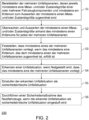
- figure 2 shows a sequence of the method 100 for detecting an accident situation of the commercial vehicle 200, wherein the accident situation can be assigned to at least one of several accident scenarios, which include at least a tipping over and a skidding of the commercial vehicle 200.
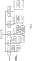
- figure 3 shows an example overview of the possible accident scenarios that can be used to identify an accident situation.
- step S1 the multiple accident scenarios are provided. At least one measured variable and/or state variable of one or more vehicle components and at least one criterion for evaluating the at least one measured variable and/or state variable are assigned to the accident scenarios.
- the present disclosure provides for up to five accident scenarios that are figure 3 are shown. However, this does not exclude any further differentiation or the provision of further accident scenarios.
- figure 3 shows the categorization of a possible accident situation into the five accident scenarios, which can also be referred to as categories.
- Each of these accident scenarios is assigned measured and/or state variables, which are recorded by the vehicle components that are also specified. Accordingly, the vehicle components can also be referred to as signal transmitters for the method 100 .
- the accident scenarios of the method 100 include at least a tipping over (overturn) and a skidding of the commercial vehicle 200, which are shown on the right in the overview of figure 3 are shown. If the commercial vehicle 200 is a truck or semi-trailer truck, it can be determined at the same time as the commercial vehicle 200 is skidding whether the train combination is or has also buckled.
- a state of the ESP 20 and a speed difference determined by the ESP 20 between two vehicle wheels arranged on a vehicle axle can be assigned as measurement and/or state variables to the overturning as an accident scenario.
- the ESP 20 may preferably include a rollover prevention (ROP) function.
- ROP rollover prevention
- a lateral acceleration of commercial vehicle 200 determined by means of ESP 20 can also be taken into account.
- a state of the ESP 20 and a yawing moment of the commercial vehicle 200 measured by means of the ESP 20 can be assigned as measurement and/or state variables to skidding as an accident scenario.
- the ESP 20 can preferably have a yaw control (YC) include.
- YC yaw control
- a transverse acceleration of commercial vehicle 200 determined by means of ESP 20 can also be taken into account here.
- the accident scenarios may further include one of a front collision (frontal collision), a rear collision (rear-end collision), and a side collision of the utility vehicle 200 .
- a state of the airbag control device 24 and a state of the emergency brake assistance system 22 can be assigned as measurement and/or state variables to the frontal collision as an accident scenario.
- a residual speed of commercial vehicle 200 detected by means of emergency brake assistance system 22 in the event of a collision can be assigned to the front collision as an accident scenario as one of the measured and/or state variables.
- the rear-end collision as an accident scenario can be assigned a status of a rear lighting device 26 and a longitudinal acceleration of commercial vehicle 200 detected by means of an airbag control device 24 as measurement and/or status variables.
- a state of the side lighting device 28 and a transverse acceleration of the commercial vehicle 200 measured by means of the ESP can be assigned as measured and/or state variables to the side collision as an accident scenario.
- a state of the electrical lines 30 can be assigned as one of the measurement and/or state variables to the side collision as an accident scenario.
- step S2 the at least one measurement and/or state variable is monitored and evaluated using the at least one criterion for each of the multiple accident scenarios.
- all the measurement and/or status variables assigned to the accident scenarios e.g. B. can be monitored simultaneously.
- Sequential monitoring is also conceivable, with z. B. each accident scenario or the at least one measurement and/or state variable assigned to the respective accident scenario is successively retrieved and monitored.
- step S3 it is determined that at least one of the multiple accident scenarios is present if the at least one criterion that is assigned to the at least one of the multiple accident scenarios is met.
- the overturning is present as an accident scenario if a criterion assigned to the overturning as an accident scenario is met, that the state of ESP 20 indicates that ESP 20 is intervening in a driving operation of commercial vehicle 200 and all wheels of commercial vehicle 200 brakes, and the differential speed is above a differential speed limit value.
- skidding is present as an accident scenario if a criterion assigned to skidding as an accident scenario is met, that the state of ESP 20 indicates that ESP 20 intervenes in driving operation of commercial vehicle 200 and selectively wheels of commercial vehicle 200 to compensate oversteering or understeering of commercial vehicle 200, and the yaw moment is above a yaw moment limit value or does not fall below a yaw moment limit value.
- the front-end collision is present as an accident scenario if a criterion assigned to the front-end collision as an accident scenario is met, that the state of the airbag control unit 24 indicates that an airbag has been or is being fired, and the state of the emergency brake assistance system 22 indicates that a collision is unavoidable. If the residual speed of commercial vehicle 200 in the event of a collision is also available as one of the measurement and/or state variables, it can be determined that the front collision is present as an accident scenario if a criterion assigned to the front collision as an accident scenario is met, that the residual speed is above a residual speed limit lies.
- the rear-end collision is present as an accident scenario if a criterion assigned to the rear-end collision as an accident scenario is met, that the state of rear lighting device 26 indicates a defect and the longitudinal acceleration is above a longitudinal acceleration limit value.
- the side collision is present as an accident scenario if a criterion assigned to the side collision as an accident scenario is met, that the state of side lighting device 28 indicates a defect, and the lateral acceleration is above a lateral acceleration limit value. If the state of the electrical lines 30 is also assigned as one of the measurement and/or state variables, it can be determined that the side collision is present as an accident scenario if a criterion assigned to the side collision as an accident scenario is met, that the state of the electrical Lines 30 indicates a severing of one or more of the electrical lines 30 .
- An accident situation is identified in step S4 if it is determined that at least one of the multiple accident scenarios is present.
- Several accident scenarios can also be present at the same time.
- the commercial vehicle can be caused to skid by a side collision, so that the method 100 can determine that the skid and the side collision are present as accident scenarios.
- the method 100 may further include steps S5 and S6.
- step S5 the recognized accident situation is classified as a safety-critical accident situation.
- the recognized accident situation can be classified as a safety-critical accident situation if it is determined that z. B. skidding as an accident scenario and at the same time the rear-end collision and/or the side collision as an accident scenario.
- a safety-critical accident situation can exist in the case of tipping over as an accident scenario or a frontal collision as an accident scenario when the residual speed is above the residual speed limit value.
- step S6 a safety measure is carried out by utility vehicle 200 if the recognized accident situation is classified as a safety-critical accident situation.
- the implementation of a safety measure may include switching off the high-voltage network 80 and / or the hydrogen supply 82 of the commercial vehicle 200.
Landscapes
- Engineering & Computer Science (AREA)
- Transportation (AREA)
- Mechanical Engineering (AREA)
- Automation & Control Theory (AREA)
- Physics & Mathematics (AREA)
- Mathematical Physics (AREA)
- Electric Propulsion And Braking For Vehicles (AREA)
Applications Claiming Priority (1)
| Application Number | Priority Date | Filing Date | Title |
|---|---|---|---|
| DE102021130478.4A DE102021130478A1 (de) | 2021-11-22 | 2021-11-22 | Verfahren zur Erkennung einer Unfallsituation eines Nutzfahrzeugs |
Publications (3)
| Publication Number | Publication Date |
|---|---|
| EP4183643A1 true EP4183643A1 (fr) | 2023-05-24 |
| EP4183643C0 EP4183643C0 (fr) | 2025-09-03 |
| EP4183643B1 EP4183643B1 (fr) | 2025-09-03 |
Family
ID=84330689
Family Applications (1)
| Application Number | Title | Priority Date | Filing Date |
|---|---|---|---|
| EP22206276.2A Active EP4183643B1 (fr) | 2021-11-22 | 2022-11-09 | Procédé de détection d'une situation d'accident d'un véhicule utilitaire |
Country Status (2)
| Country | Link |
|---|---|
| EP (1) | EP4183643B1 (fr) |
| DE (1) | DE102021130478A1 (fr) |
Citations (9)
| Publication number | Priority date | Publication date | Assignee | Title |
|---|---|---|---|---|
| DE10057563A1 (de) * | 2000-11-21 | 2002-05-23 | Volkswagen Ag | Beleuchtungseinrichtung für ein Kraftfahrzeug |
| DE10239406A1 (de) * | 2002-08-28 | 2004-03-11 | Robert Bosch Gmbh | Vorrichtung zur Erkennung eines Fahrzeugüberschlags |
| WO2005082680A1 (fr) * | 2004-03-01 | 2005-09-09 | Continental Teves Ag & Co.Ohg | Dispositif pour determiner une tendance au basculement |
| DE102007059414A1 (de) * | 2007-12-10 | 2009-06-18 | Robert Bosch Gmbh | Verfahren und Anordnung zur Ansteuerung von Sicherheitsmitteln für ein Fahrzeug |
| DE102011118149A1 (de) * | 2011-11-10 | 2013-05-16 | Gm Global Technology Operations, Llc | Verfahren zum Betreiben eines Sicherheitssystems eines Kraftfahrzeugs und Sicherheitssystem für ein Kraftfahrzeug |
| DE102012107188A1 (de) * | 2012-08-06 | 2014-02-06 | Continental Automotive Gmbh | Verfahren zur Aktivierung von Schutzmaßnahmen in Fahrzeugen beim Erkennen einer Gefährdungssituation |
| DE112015000157T5 (de) * | 2014-06-17 | 2016-05-25 | Mazda Motor Corporation | Fahrzeug-Notfallalarmgerät |
| EP3286032A1 (fr) * | 2015-04-21 | 2018-02-28 | Volkswagen Aktiengesellschaft | Procédé et dispositif pour un système d'énergie à haute tension d'un véhicule |
| DE102017201936A1 (de) * | 2017-02-08 | 2018-08-09 | Robert Bosch Gmbh | Verfahren zur Reduzierung eines Kollisionsschadens |
Family Cites Families (7)
| Publication number | Priority date | Publication date | Assignee | Title |
|---|---|---|---|---|
| DE10128692B4 (de) | 2000-06-14 | 2014-09-25 | Hino Jidosha Kabushiki Kaisha | Bremseinrichtung für Lastzüge |
| DE102004029374A1 (de) | 2004-06-17 | 2006-01-05 | Robert Bosch Gmbh | Verfahren zur Bestimmung einer Auslöseentscheidung für Rückhaltemittel eines Kraftfahrzeuges |
| DE102005008976A1 (de) | 2005-02-28 | 2006-08-31 | Robert Bosch Gmbh | Verfahren und Vorrichtung zum Bestimmen eines Initialschwimmwinkels zur Schleudererkennung bei Überrollsensierung |
| DE102006057744A1 (de) | 2006-12-07 | 2008-07-10 | Siemens Ag | Dynamischer Geschwindigkeitsassistent für ein Fahrerassistenzsystem |
| DE102009058154A1 (de) | 2009-12-12 | 2011-06-16 | Wabco Gmbh | Fahrerassistenzsystem für ein Fahrzeug, insbesondere Nutzfahrzeug, sowie Verfahren zum Steuern eines Bremssystems |
| DE102010015545B4 (de) | 2010-04-20 | 2020-08-13 | Werner Bernzen | Verfahren und Vorrichtung zur Ansteuerung mindestens einer reversiblen Insassenschutzvorrichtung eines Fahrzeuges |
| KR101766147B1 (ko) | 2016-06-16 | 2017-08-07 | 현대자동차주식회사 | 능수동 안전 장치를 통합하여 작동하는 방법 |
-
2021
- 2021-11-22 DE DE102021130478.4A patent/DE102021130478A1/de active Pending
-
2022
- 2022-11-09 EP EP22206276.2A patent/EP4183643B1/fr active Active
Patent Citations (9)
| Publication number | Priority date | Publication date | Assignee | Title |
|---|---|---|---|---|
| DE10057563A1 (de) * | 2000-11-21 | 2002-05-23 | Volkswagen Ag | Beleuchtungseinrichtung für ein Kraftfahrzeug |
| DE10239406A1 (de) * | 2002-08-28 | 2004-03-11 | Robert Bosch Gmbh | Vorrichtung zur Erkennung eines Fahrzeugüberschlags |
| WO2005082680A1 (fr) * | 2004-03-01 | 2005-09-09 | Continental Teves Ag & Co.Ohg | Dispositif pour determiner une tendance au basculement |
| DE102007059414A1 (de) * | 2007-12-10 | 2009-06-18 | Robert Bosch Gmbh | Verfahren und Anordnung zur Ansteuerung von Sicherheitsmitteln für ein Fahrzeug |
| DE102011118149A1 (de) * | 2011-11-10 | 2013-05-16 | Gm Global Technology Operations, Llc | Verfahren zum Betreiben eines Sicherheitssystems eines Kraftfahrzeugs und Sicherheitssystem für ein Kraftfahrzeug |
| DE102012107188A1 (de) * | 2012-08-06 | 2014-02-06 | Continental Automotive Gmbh | Verfahren zur Aktivierung von Schutzmaßnahmen in Fahrzeugen beim Erkennen einer Gefährdungssituation |
| DE112015000157T5 (de) * | 2014-06-17 | 2016-05-25 | Mazda Motor Corporation | Fahrzeug-Notfallalarmgerät |
| EP3286032A1 (fr) * | 2015-04-21 | 2018-02-28 | Volkswagen Aktiengesellschaft | Procédé et dispositif pour un système d'énergie à haute tension d'un véhicule |
| DE102017201936A1 (de) * | 2017-02-08 | 2018-08-09 | Robert Bosch Gmbh | Verfahren zur Reduzierung eines Kollisionsschadens |
Also Published As
| Publication number | Publication date |
|---|---|
| EP4183643C0 (fr) | 2025-09-03 |
| DE102021130478A1 (de) | 2023-05-25 |
| EP4183643B1 (fr) | 2025-09-03 |
Similar Documents
| Publication | Publication Date | Title |
|---|---|---|
| EP2058190B1 (fr) | Système d'assistance à la conduite pour des combinaisons véhicule tracteur-remorque | |
| EP2795345B1 (fr) | Procédé et dispositif pour la détermination de la position de montage d'un module capteur dans un véhicule et véhicule doté d'un tel dispositif | |
| EP1034985B1 (fr) | Méthode et dispositif de commande d'un système de retenue d' un véhicule | |
| DE102007025960A1 (de) | Verfahren zur Einstellung einer Bremsanlage in einem Fahrzeug | |
| WO1999047389A1 (fr) | Procede de commande du fonctionnement de dispositifs de protection des occupants d'un vehicule a moteur en association avec le systeme de securite de la dynamique de conduite | |
| DE102011085843B4 (de) | Verfahren und Vorrichtung zur Analyse einer Kollision eines Fahrzeugs | |
| DE102004024265B4 (de) | Sicherheitssystem zum Betrieb wenigstens einer elektrisch betätigbaren Verschlusseinrichtung einer Tür eines Fahrzeuges | |
| EP1571058B1 (fr) | Procédé de freinage d'un véhicule | |
| DE102012107188B4 (de) | Verfahren zur Aktivierung von Schutzmaßnahmen in Fahrzeugen beim Erkennen einer Gefährdungssituation | |
| EP1932735B1 (fr) | Procédé et système d'empêchement de collisions multiples et d'atténuation de leurs effects | |
| DE102012107186B4 (de) | Verfahren zum Erkennen einer Gefährdungssituation eines Fahrzeugs anhand von zumindest einem Umfeldsensor und zumindest einem Inertialsensor | |
| EP1536986A1 (fr) | Dispositif pour identifier un tonneau effectue par un vehicule | |
| EP2900528B1 (fr) | Procédé et dispositif pour le fonctionnement d'un véhicule et véhicule équipé d'un tel dispositif | |
| DE10345748B4 (de) | Verfahren zum Erkennen des Andockens von Fahrzeugen | |
| EP4183643B1 (fr) | Procédé de détection d'une situation d'accident d'un véhicule utilitaire | |
| EP4200173B1 (fr) | Procédé permettant de sécuriser un véhicule | |
| DE102008003079B4 (de) | Verfahren und Steuergerät zur Ansteuerung von Personenschutzmitteln für ein Fahrzeug | |
| DE102021001918A1 (de) | Verfahren zur Überwachung eines Fahrzeuges | |
| DE102009002379B4 (de) | Auslösevorrichtung und Verfahren zur Auslösung von zumindest einem irreversiblen und/oder reversiblen Personenrückhaltemittel für einen Insassen in einem Fahrzeug | |
| DE10009540A1 (de) | Verfahren und Vorrichtung zum Bestimmen der Position und/oder des Gewichts eines in einem Kraftfahrzeug befindlichen Massenkörpers, insbesondere einer auf einem Fahrzeugsitz befindlichen Person | |
| DE102021202529A1 (de) | Verfahren zur Bestimmung der Geschwindigkeit eines Fahrzeugs bei einem Unfall | |
| DE10360769B4 (de) | Verfahren und Vorrichtung zum Auslösen mindestens einer Insassenschutzeinrichtung in einem Fahrzeug | |
| DE102012107184B4 (de) | Verfahren zum Erkennen einer Gefährdungssituation eines Fahrzeugs anhand von zumindest einem Umfeldsensor und zumindest einem Inertialsensor | |
| DE102018001926A1 (de) | Verfahren zumindest zur Verringerung einer Kollisionsschwere | |
| DE102007019432A1 (de) | Vorrichtung und Verfahren zur Ansteuerung von Personenschutzmitteln |
Legal Events
| Date | Code | Title | Description |
|---|---|---|---|
| PUAI | Public reference made under article 153(3) epc to a published international application that has entered the european phase |
Free format text: ORIGINAL CODE: 0009012 |
|
| STAA | Information on the status of an ep patent application or granted ep patent |
Free format text: STATUS: THE APPLICATION HAS BEEN PUBLISHED |
|
| AK | Designated contracting states |
Kind code of ref document: A1 Designated state(s): AL AT BE BG CH CY CZ DE DK EE ES FI FR GB GR HR HU IE IS IT LI LT LU LV MC ME MK MT NL NO PL PT RO RS SE SI SK SM TR |
|
| STAA | Information on the status of an ep patent application or granted ep patent |
Free format text: STATUS: REQUEST FOR EXAMINATION WAS MADE |
|
| 17P | Request for examination filed |
Effective date: 20231124 |
|
| RBV | Designated contracting states (corrected) |
Designated state(s): AL AT BE BG CH CY CZ DE DK EE ES FI FR GB GR HR HU IE IS IT LI LT LU LV MC ME MK MT NL NO PL PT RO RS SE SI SK SM TR |
|
| RIC1 | Information provided on ipc code assigned before grant |
Ipc: B60W 30/08 20120101ALI20250211BHEP Ipc: B60W 40/114 20120101ALI20250211BHEP Ipc: B60W 40/112 20120101ALI20250211BHEP Ipc: B60W 40/10 20120101ALI20250211BHEP Ipc: B60W 30/085 20120101ALI20250211BHEP Ipc: B60T 8/1755 20060101AFI20250211BHEP |
|
| RIC1 | Information provided on ipc code assigned before grant |
Ipc: B60W 30/08 20120101ALI20250307BHEP Ipc: B60W 40/114 20120101ALI20250307BHEP Ipc: B60W 40/112 20120101ALI20250307BHEP Ipc: B60W 40/10 20120101ALI20250307BHEP Ipc: B60W 30/085 20120101ALI20250307BHEP Ipc: B60T 8/1755 20060101AFI20250307BHEP |
|
| GRAP | Despatch of communication of intention to grant a patent |
Free format text: ORIGINAL CODE: EPIDOSNIGR1 |
|
| STAA | Information on the status of an ep patent application or granted ep patent |
Free format text: STATUS: GRANT OF PATENT IS INTENDED |
|
| INTG | Intention to grant announced |
Effective date: 20250509 |
|
| GRAS | Grant fee paid |
Free format text: ORIGINAL CODE: EPIDOSNIGR3 |
|
| GRAA | (expected) grant |
Free format text: ORIGINAL CODE: 0009210 |
|
| STAA | Information on the status of an ep patent application or granted ep patent |
Free format text: STATUS: THE PATENT HAS BEEN GRANTED |
|
| AK | Designated contracting states |
Kind code of ref document: B1 Designated state(s): AL AT BE BG CH CY CZ DE DK EE ES FI FR GB GR HR HU IE IS IT LI LT LU LV MC ME MK MT NL NO PL PT RO RS SE SI SK SM TR |
|
| REG | Reference to a national code |
Ref country code: CH Ref legal event code: EP |
|
| REG | Reference to a national code |
Ref country code: DE Ref legal event code: R096 Ref document number: 502022005281 Country of ref document: DE |
|
| REG | Reference to a national code |
Ref country code: IE Ref legal event code: FG4D Free format text: LANGUAGE OF EP DOCUMENT: GERMAN |
|
| U01 | Request for unitary effect filed |
Effective date: 20250925 |
|
| U07 | Unitary effect registered |
Designated state(s): AT BE BG DE DK EE FI FR IT LT LU LV MT NL PT RO SE SI Effective date: 20251007 |
|
| U20 | Renewal fee for the european patent with unitary effect paid |
Year of fee payment: 4 Effective date: 20251126 |
|
| PG25 | Lapsed in a contracting state [announced via postgrant information from national office to epo] |
Ref country code: NO Free format text: LAPSE BECAUSE OF FAILURE TO SUBMIT A TRANSLATION OF THE DESCRIPTION OR TO PAY THE FEE WITHIN THE PRESCRIBED TIME-LIMIT Effective date: 20251203 |
|
| PG25 | Lapsed in a contracting state [announced via postgrant information from national office to epo] |
Ref country code: HR Free format text: LAPSE BECAUSE OF FAILURE TO SUBMIT A TRANSLATION OF THE DESCRIPTION OR TO PAY THE FEE WITHIN THE PRESCRIBED TIME-LIMIT Effective date: 20250903 |
|
| PG25 | Lapsed in a contracting state [announced via postgrant information from national office to epo] |
Ref country code: GR Free format text: LAPSE BECAUSE OF FAILURE TO SUBMIT A TRANSLATION OF THE DESCRIPTION OR TO PAY THE FEE WITHIN THE PRESCRIBED TIME-LIMIT Effective date: 20251204 |
|
| PG25 | Lapsed in a contracting state [announced via postgrant information from national office to epo] |
Ref country code: PL Free format text: LAPSE BECAUSE OF FAILURE TO SUBMIT A TRANSLATION OF THE DESCRIPTION OR TO PAY THE FEE WITHIN THE PRESCRIBED TIME-LIMIT Effective date: 20250903 |
|
| PG25 | Lapsed in a contracting state [announced via postgrant information from national office to epo] |
Ref country code: RS Free format text: LAPSE BECAUSE OF FAILURE TO SUBMIT A TRANSLATION OF THE DESCRIPTION OR TO PAY THE FEE WITHIN THE PRESCRIBED TIME-LIMIT Effective date: 20251203 |
|
| PG25 | Lapsed in a contracting state [announced via postgrant information from national office to epo] |
Ref country code: ES Free format text: LAPSE BECAUSE OF FAILURE TO SUBMIT A TRANSLATION OF THE DESCRIPTION OR TO PAY THE FEE WITHIN THE PRESCRIBED TIME-LIMIT Effective date: 20250903 |
|
| PG25 | Lapsed in a contracting state [announced via postgrant information from national office to epo] |
Ref country code: SM Free format text: LAPSE BECAUSE OF FAILURE TO SUBMIT A TRANSLATION OF THE DESCRIPTION OR TO PAY THE FEE WITHIN THE PRESCRIBED TIME-LIMIT Effective date: 20250903 |
|
| PG25 | Lapsed in a contracting state [announced via postgrant information from national office to epo] |
Ref country code: IS Free format text: LAPSE BECAUSE OF FAILURE TO SUBMIT A TRANSLATION OF THE DESCRIPTION OR TO PAY THE FEE WITHIN THE PRESCRIBED TIME-LIMIT Effective date: 20260103 |
|
| PG25 | Lapsed in a contracting state [announced via postgrant information from national office to epo] |
Ref country code: CZ Free format text: LAPSE BECAUSE OF FAILURE TO SUBMIT A TRANSLATION OF THE DESCRIPTION OR TO PAY THE FEE WITHIN THE PRESCRIBED TIME-LIMIT Effective date: 20250903 |
|
| PG25 | Lapsed in a contracting state [announced via postgrant information from national office to epo] |
Ref country code: SK Free format text: LAPSE BECAUSE OF FAILURE TO SUBMIT A TRANSLATION OF THE DESCRIPTION OR TO PAY THE FEE WITHIN THE PRESCRIBED TIME-LIMIT Effective date: 20250903 |