EP4183994B1 - Poröse haut mit mehreren bändern und schalldämmplatte mit solch einer porösen haut - Google Patents
Poröse haut mit mehreren bändern und schalldämmplatte mit solch einer porösen haut Download PDFInfo
- Publication number
- EP4183994B1 EP4183994B1 EP22206381.0A EP22206381A EP4183994B1 EP 4183994 B1 EP4183994 B1 EP 4183994B1 EP 22206381 A EP22206381 A EP 22206381A EP 4183994 B1 EP4183994 B1 EP 4183994B1
- Authority
- EP
- European Patent Office
- Prior art keywords
- strips
- porous skin
- strip
- skin
- contour
- Prior art date
- Legal status (The legal status is an assumption and is not a legal conclusion. Google has not performed a legal analysis and makes no representation as to the accuracy of the status listed.)
- Active
Links
Images
Classifications
-
- G—PHYSICS
- G10—MUSICAL INSTRUMENTS; ACOUSTICS
- G10K—SOUND-PRODUCING DEVICES; METHODS OR DEVICES FOR PROTECTING AGAINST, OR FOR DAMPING, NOISE OR OTHER ACOUSTIC WAVES IN GENERAL; ACOUSTICS NOT OTHERWISE PROVIDED FOR
- G10K11/00—Methods or devices for transmitting, conducting or directing sound in general; Methods or devices for protecting against, or for damping, noise or other acoustic waves in general
- G10K11/16—Methods or devices for protecting against, or for damping, noise or other acoustic waves in general
- G10K11/172—Methods or devices for protecting against, or for damping, noise or other acoustic waves in general using resonance effects
-
- G—PHYSICS
- G10—MUSICAL INSTRUMENTS; ACOUSTICS
- G10K—SOUND-PRODUCING DEVICES; METHODS OR DEVICES FOR PROTECTING AGAINST, OR FOR DAMPING, NOISE OR OTHER ACOUSTIC WAVES IN GENERAL; ACOUSTICS NOT OTHERWISE PROVIDED FOR
- G10K11/00—Methods or devices for transmitting, conducting or directing sound in general; Methods or devices for protecting against, or for damping, noise or other acoustic waves in general
- G10K11/16—Methods or devices for protecting against, or for damping, noise or other acoustic waves in general
- G10K11/162—Selection of materials
-
- B—PERFORMING OPERATIONS; TRANSPORTING
- B64—AIRCRAFT; AVIATION; COSMONAUTICS
- B64D—EQUIPMENT FOR FITTING IN OR TO AIRCRAFT; FLIGHT SUITS; PARACHUTES; ARRANGEMENT OR MOUNTING OF POWER PLANTS OR PROPULSION TRANSMISSIONS IN AIRCRAFT
- B64D33/00—Arrangement in aircraft of power plant parts or auxiliaries not otherwise provided for
- B64D33/02—Arrangement in aircraft of power plant parts or auxiliaries not otherwise provided for of combustion air intakes
-
- F—MECHANICAL ENGINEERING; LIGHTING; HEATING; WEAPONS; BLASTING
- F02—COMBUSTION ENGINES; HOT-GAS OR COMBUSTION-PRODUCT ENGINE PLANTS
- F02C—GAS-TURBINE PLANTS; AIR INTAKES FOR JET-PROPULSION PLANTS; CONTROLLING FUEL SUPPLY IN AIR-BREATHING JET-PROPULSION PLANTS
- F02C7/00—Features, components parts, details or accessories, not provided for in, or of interest apart form groups F02C1/00 - F02C6/00; Air intakes for jet-propulsion plants
- F02C7/04—Air intakes for gas-turbine plants or jet-propulsion plants
- F02C7/045—Air intakes for gas-turbine plants or jet-propulsion plants having provisions for noise suppression
-
- G—PHYSICS
- G10—MUSICAL INSTRUMENTS; ACOUSTICS
- G10K—SOUND-PRODUCING DEVICES; METHODS OR DEVICES FOR PROTECTING AGAINST, OR FOR DAMPING, NOISE OR OTHER ACOUSTIC WAVES IN GENERAL; ACOUSTICS NOT OTHERWISE PROVIDED FOR
- G10K11/00—Methods or devices for transmitting, conducting or directing sound in general; Methods or devices for protecting against, or for damping, noise or other acoustic waves in general
- G10K11/16—Methods or devices for protecting against, or for damping, noise or other acoustic waves in general
-
- G—PHYSICS
- G10—MUSICAL INSTRUMENTS; ACOUSTICS
- G10K—SOUND-PRODUCING DEVICES; METHODS OR DEVICES FOR PROTECTING AGAINST, OR FOR DAMPING, NOISE OR OTHER ACOUSTIC WAVES IN GENERAL; ACOUSTICS NOT OTHERWISE PROVIDED FOR
- G10K11/00—Methods or devices for transmitting, conducting or directing sound in general; Methods or devices for protecting against, or for damping, noise or other acoustic waves in general
- G10K11/16—Methods or devices for protecting against, or for damping, noise or other acoustic waves in general
- G10K11/162—Selection of materials
- G10K11/168—Plural layers of different materials, e.g. sandwiches
-
- B—PERFORMING OPERATIONS; TRANSPORTING
- B64—AIRCRAFT; AVIATION; COSMONAUTICS
- B64D—EQUIPMENT FOR FITTING IN OR TO AIRCRAFT; FLIGHT SUITS; PARACHUTES; ARRANGEMENT OR MOUNTING OF POWER PLANTS OR PROPULSION TRANSMISSIONS IN AIRCRAFT
- B64D33/00—Arrangement in aircraft of power plant parts or auxiliaries not otherwise provided for
- B64D33/02—Arrangement in aircraft of power plant parts or auxiliaries not otherwise provided for of combustion air intakes
- B64D2033/0206—Arrangement in aircraft of power plant parts or auxiliaries not otherwise provided for of combustion air intakes comprising noise reduction means, e.g. acoustic liners
-
- B—PERFORMING OPERATIONS; TRANSPORTING
- B64—AIRCRAFT; AVIATION; COSMONAUTICS
- B64D—EQUIPMENT FOR FITTING IN OR TO AIRCRAFT; FLIGHT SUITS; PARACHUTES; ARRANGEMENT OR MOUNTING OF POWER PLANTS OR PROPULSION TRANSMISSIONS IN AIRCRAFT
- B64D33/00—Arrangement in aircraft of power plant parts or auxiliaries not otherwise provided for
- B64D33/02—Arrangement in aircraft of power plant parts or auxiliaries not otherwise provided for of combustion air intakes
- B64D2033/0266—Arrangement in aircraft of power plant parts or auxiliaries not otherwise provided for of combustion air intakes specially adapted for particular type of power plants
- B64D2033/0273—Arrangement in aircraft of power plant parts or auxiliaries not otherwise provided for of combustion air intakes specially adapted for particular type of power plants for jet engines
-
- F—MECHANICAL ENGINEERING; LIGHTING; HEATING; WEAPONS; BLASTING
- F05—INDEXING SCHEMES RELATING TO ENGINES OR PUMPS IN VARIOUS SUBCLASSES OF CLASSES F01-F04
- F05D—INDEXING SCHEME FOR ASPECTS RELATING TO NON-POSITIVE-DISPLACEMENT MACHINES OR ENGINES, GAS-TURBINES OR JET-PROPULSION PLANTS
- F05D2250/00—Geometry
- F05D2250/10—Two-dimensional
- F05D2250/18—Two-dimensional patterned
- F05D2250/182—Two-dimensional patterned crenellated, notched
-
- F—MECHANICAL ENGINEERING; LIGHTING; HEATING; WEAPONS; BLASTING
- F05—INDEXING SCHEMES RELATING TO ENGINES OR PUMPS IN VARIOUS SUBCLASSES OF CLASSES F01-F04
- F05D—INDEXING SCHEME FOR ASPECTS RELATING TO NON-POSITIVE-DISPLACEMENT MACHINES OR ENGINES, GAS-TURBINES OR JET-PROPULSION PLANTS
- F05D2260/00—Function
- F05D2260/96—Preventing, counteracting or reducing vibration or noise
- F05D2260/963—Preventing, counteracting or reducing vibration or noise by Helmholtz resonators
Definitions
- the present invention relates to a porous skin for an acoustic attenuation panel, as well as to an acoustic attenuation panel provided with such a porous skin.
- an acoustic attenuation panel generally comprises an acoustic structure provided with a plate having good sound absorption properties, particularly for the frequencies of the most annoying noises.
- This acoustic structure used for sound absorption can be made of cellular material, but also in a foam-based material or in a fibrous material.
- Such an acoustic attenuation panel is, in general, also provided on one of its two faces with a porous (i.e. perforated) skin called "resistive" and, on the other face, with a rear skin called non-perforated “reflective”.
- the resistive skin allows sound waves (or acoustic waves) to penetrate the acoustic structure where they are attenuated.
- the resistive skin is perforated, it can also allow flow, for example flow of a fluid such as air, to enter the acoustic structure.
- flow for example flow of a fluid such as air
- Such a flow which enters the acoustic structure is likely to disrupt the acoustic attenuation, in particular by creating undesirable phenomena which reduce the effective portion of the openings of the resistive skin.
- the object of the present invention is to propose a solution making it possible to remedy the aforementioned drawback. To do this, it concerns a porous skin for an acoustic attenuation panel, said porous skin being intended to be subjected to a flow of fluid.
- the porous skin comprises a plurality of strips which are arranged transversely to the fluid flow and which, successively, overlap laterally, each strip upstream of the fluid flow overlapping the strip or strips downstream of said fluid flow, each of said bands comprises a first lateral edge called upstream and a second lateral edge called downstream, at least one of said lateral edges comprising a contour forming a line with deviations, and the arrangement of the bands and the contour(s) of their lateral edges are configured to provide, between the strips, openings communicating from an external face of the porous skin to an internal face of said porous skin, and to prevent the flow of fluid from penetrating said openings.
- a “line with deviations” means a non-straight line, as specified below.
- a porous skin configured to be able to pass through it by sound waves, while being capable, when subjected to a flow of fluid, of preventing this flow of fluid from passing through it. Also, when used as a resistive skin on an acoustic attenuation panel, it is able, by preventing any flow of fluid to pass through it, to avoid the appearance of the aforementioned undesirable phenomena and thus to remedy the disadvantage mentioned above.
- the overlapping of the strips creates contact surfaces between two successive strips, and said strips are fixed together at at least some of said contact surfaces.
- At least some of said openings are created by shapes adapted on the one hand from the contour of the downstream lateral edge of a first strip and on the other hand from the contour of the upstream lateral edge of a second strip directly downstream of said first strip, each of the openings thus created being covered by a third strip which is directly upstream of said first strip and which overhangs this first strip towards the downstream.
- the contour of at least one of the side edges comprises, at least partially, a curvilinear line.
- the contour of at least one of the side edges comprises, at least partially, a broken line.
- said strips are of identical shape. In another embodiment, at least some of said strips may be of different shapes from each other.
- said strips have, at at least one of their lateral edges on one of their faces, a discontinuity forming at least one flat surface.
- the present invention also relates to an acoustic attenuation panel comprising at least one acoustic structure provided with a porous skin such as that described above.
- the acoustic structure comprises at least one cellular structure provided, on one of its faces, with a so-called reflective rear skin and, on the other face, with said porous skin.
- the porous skin 1 is a skin intended to be arranged in an acoustic attenuation panel ( figure 7 ).
- acoustic attenuation panel is meant an element, preferably in the form of a plate, intended to be fixed to a surface in order to reduce surrounding noise, for example by trapping and/or dampening sound waves (or sound waves). acoustics).
- an acoustic attenuation panel can correspond to any structure having sound absorption properties.
- the porous skin 1 is capable of being subjected, on an external face, to a flow of fluid E, for example a flow of air, as illustrated by an arrow on the figures 1 to 7 .
- the porous skin 1 is configured to be permeable to sound waves while preventing the flow of fluid E from passing through it, as described below.
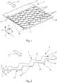
- the porous skin 1 comprises, as shown in the figure 1 , a plurality of strips 2 which, successively, overlap laterally.
- overlap of two strips means the fact that one of said strips overlaps, partly with surface contact, on the other strip.
- lateral overlap of two strips designates the arrangement in the width direction of said strips. This arrangement will be described in more detail later in the description.
- the strips 2 are made of aluminum and have, for example, a thickness of the order of a hundredth of a millimeter.
- they can also be made from other materials, and in particular from a metallic material other than aluminum, from a plastic material or from a composite material.
- each of the strips 2 of the porous skin 1 has an elongated shape extending in a so-called longitudinal direction X, which is substantially orthogonal to a so-called lateral direction Y.
- the strips 2 and the porous skin 1 are arranged so that the direction Y (lateral direction of the strips) corresponds to the direction of the fluid flow E.
- the strips 2 and the skin porous 1 can be arranged so that the lateral direction Y of the strips and the direction of the fluid flow E present between them a non-zero angle, which however remains less than 90 degrees.
- the porous skin 1 has a so-called external face 3 intended to be subjected to the flow of fluid E and a so-called internal face 4 opposite the face 3, as shown in figure 1 .
- the direction X and the direction Y define a so-called horizontal plane P which is orthogonal to a so-called vertical direction Z.
- the Z direction is oriented upwards.
- Face 3 is oriented in the direction of the Z direction and face 4 is oriented in the direction opposite to the Z direction.
- each strip 2 has an external face 5 oriented in the direction of the Z direction and an internal face 6 oriented in the direction opposite to the direction Z.
- the faces 5 and 6 are parallel to each other. However, in particular embodiments, they may be non-parallel.
- the strips 2 are inclined so that their internal and external faces have an angle ⁇ with respect to the horizontal plane P (therefore substantially with respect to the flow of fluid E).
- the strips 2 also have two side edges, namely the edges oriented in the direction Y.
- each strip 2 is in particular provided with a lateral edge 7 called "upstream” (located upstream in direction Y, therefore upstream in the direction of the fluid flow E) and with a lateral edge 8 called “ downstream” (located downstream in direction Y, therefore downstream in the direction of fluid flow E).
- the bands 2 overlapping laterally, for each of them, the lateral edge 7 is never in direct contact with the flow of fluid E while the lateral edge 8 is in contact, at least partially, with said flow of fluid E.
- the side edge 7 comprises a contour 9 and the side edge 8 comprises a contour 10.
- Each of the contours 9 and 10 presents a line with deviations.
- a “line with deviations” designates a non-straight line, that is to say a line which may include a broken line (or polygonal line), namely a succession of straight segments with different orientations, and/or one or more curved lines.
- a contour forming a line with deviations is therefore a contour which is not completely straight (or not completely rectilinear).
- the bands 2 are arranged transversely to the flow of fluid E so that each band upstream of said flow overlaps (that is to say partially covers) the downstream band.
- the arrangement of the bands 2 and the shape of the contours 9 and 10 of the side edges 7 and 8 are configured to provide openings 11 between two successive strips 2.
- the strips 2 being inclined relative to the horizontal plane P, said openings 11 provided between two strips 2 are covered, at least in part, by a third strip 2 located upstream of the first two. The openings 11 are therefore accessible only from the downstream of this third strip.
- the openings 11 thus created are through, which allows sound waves to move through said openings 11 in order to pass through the porous skin 1 following a path represented schematically by an arrow S on the Figure 4 .
- the openings 11 make it possible, however, to prevent the flow of fluid E from penetrating the openings 11, and therefore from passing through the porous skin 1.
- the inclination of the strips 2 and the covering of the openings 11 by said strips 2, as described above have the effect of directing the flow of fluid E along the external face 3 of the porous skin 1 over the bands 2.
- the flow of fluid E being a movement of material oriented substantially in a given direction, it runs along the external faces 5 of the strips 2 without the possibility of accessing the openings 11.
- the sound waves which correspond to mechanical vibrations, that is to say to compressions and expansions of the surrounding environment, can therefore propagate (step by step) in all directions and in particular through the openings 11 accessible from downstream.
- the dimensions (length and section) of the openings 11 can be modified by modifying at least one of the following parameters: the shape of the contours of the side edges 7 and 8, the arrangement of the strips 2 relative to each other , and the thickness of the strips 2.
- the overlap of the strips 2 creates, between two successive strips, contact surfaces 19 ( Figure 4 ).
- the contact surfaces 19 between two successive strips correspond to the interfaces (with contact) formed by longitudinal portions of the internal face of the upstream strip overlapping longitudinal portions of the external face of the downstream strip.
- the strips 2 are fixed together at at least some of these contact surfaces 19.
- they are fixed by gluing or by welding or any other means of known type.
- all bands 2 of porous skin 1 are identical.
- using a single type of strip makes it possible to simplify the manufacture of the porous skin 1 and to reduce its manufacturing cost.
- the porous skin 1 comprises a succession of at least two strips 2 different from each other, said succession being repeated laterally (in the direction Y) in order to form the plurality of strips 2 of the porous skin 1 .
- the two contours 9 and 10 of the side edges 7 and 8 each present a line with deviations.
- said contours 9 and 10 are identical, that is to say they have the same shape and one of said contours 9 and 10 can be obtained by a translation in the Y direction of the other contour.
- the shapes of the contours 9 and 10 are offset longitudinally (in the direction X) relative to each other so that one of the contours can be obtained by a translation of the other contour in a direction other than the Y direction.
- the contours of the side edges 7 and 8 have different shapes.
- the contours 9 and 10 of the side edges 7 and 8 have a curvilinear shape (that is to say a line with curves).
- the curvilinear shape corresponds to a sinusoidal shape.
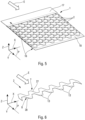
- the side edges 7 and 8 respectively comprise a contour 27 and a contour 28.
- the contours 27 and 28 both have a shape including a broken line (or polygonal line).
- the shape of the broken line forming the contours 26 and 27 corresponds to a series of trapezoidal slots.
- the contours of the side edges comprise at least one curvilinear line and at least one broken line.
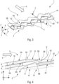
- the strips 2 are provided with a discontinuity 12 ( figure 2 ), specified below, on their external face 5 at the level of their downstream lateral edge 8.
- the discontinuity 12 forms a flat surface 13 at the free end of the lateral edge 8 ( figures 2 And 6 ).
- the flat surface 13 is slightly inclined relative to the external face 5.
- the flat surface 13 may in particular have an angle with the face 5 which is of the order of a few degrees.
- the discontinuity 12 extends over the entire length of the strip 2 parallel to the direction X.
- the contour 10, 28 of the side edge 8 is not straight and the discontinuity 12 is located at the free end of the side edge 8 , said discontinuity 12 forms a plurality of flat surfaces 13.
- Each flat surface 13 is located on a vertex or a niche of the contour 10, 28, as illustrated in the figures 2 And 6 .
- the flat surfaces 13 of the strip 2 are formed so as to be coplanar.
- the flat surfaces 13 are formed so as to be included in the same plane which is parallel to the horizontal plane P.
- This plane may in particular correspond to the plane defined by the external face 3 of the porous skin 1.
- the flat surfaces 13 make it possible to minimize the irregularities present on the surface of the external face 3 of the porous skin 1, and consequently not to not alter the aerodynamic properties of the porous skin 1, in particular by limiting drag.
- the discontinuity 12 corresponds to a chamfer.
- the discontinuity 12 can also correspond to a bevel.
- the strips 2 also include, on their internal face 6 at the level of the free end of their upstream lateral edge 7, a discontinuity 14 forming flat surfaces 15.
- the flat surfaces 15 are slightly inclined relative to the internal face 6.
- the flat surfaces 15 may in particular have an angle with the face 6 which is of the order of a few degrees.
- the flat surfaces 13 and 15 are parallel to each other. Consequently, the flat surfaces 15 are substantially included in the same plane which is parallel to the horizontal plane P. This plane can, in particular, correspond to the plane defined by the internal face 4 of the porous skin 1.
- the flat surfaces 15 make it possible to obtain a substantially flat face 4 which can serve as a contact surface for arranging the porous skin 1, for example example on a wall or a face of an acoustic attenuation panel.
- the porous skin 1 also includes a support 16 configured to structurally support the plurality of strips 2.
- the support 16 comprises a first plate 17 arranged upstream of the porous skin 1.
- the plate 17 overlaps the strip(s) 2 located most upstream of the porous skin 1.
- the support 16 also comprises a second plate 18 arranged downstream of the plurality of strips 2 and it overlaps the strip(s) 2 located most downstream of the porous skin 1.
- the strips 2 linked to the plates 17 and 18 can be fixed to the latter, for example by gluing or by welding or other .
- the support 17 can correspond to any structure capable of structurally supporting at least some and preferably all of the strips 2, such as for example a frame or a grid.
- FIG. 3 a particular embodiment of a part of the porous skin 1 comprising three successive bands is illustrated on the figures 3 and 4 .
- a fourth band is represented in finer lines on the Figure 4 in order to clearly specify the arrangement of the three successive bands described below in a porous skin 1 comprising more than three bands.
- the porous skin 1 comprises a first so-called upstream strip 2A, a second so-called intermediate strip 2B and a third so-called downstream strip 2C.
- the letter A, B or C has been added to the elements belonging, respectively, to bands 2A, 2B or 2C.
- the strips 2A, 2B and 2C have the same shape. They are arranged parallel to each other and substantially perpendicular to the flow of fluid E.
- the strips 2A, 2B and 2C are inclined relative to the horizontal plane P.
- the external faces 5A, 5B and 5C have an angle ⁇ with respect to the plane P.
- the external faces 5A, 5B and 5C are arranged so as to be in contact, at least in part, with the flow of fluid E.
- the angle ⁇ is of the order of a few degrees in order to obtain an external face 3 of the porous skin 1 which is aerodynamic.
- strip 2A is arranged so as to overlap strip 2B.
- part of the internal face 6A of the strip 2A is in contact (surface) with part of the external face 5B of the strip 2B.
- strip 2B is arranged to overlap strip 2C.
- part of the internal face 6B of the strip 2B is in contact (surface) with part of the external face 5C of the strip 2C.
- strip 2C is arranged so as to overlap another adjacent strip located downstream (shown in thin lines on the figure 4 ).
- the arrangement of the strips 2A, 2B and 2C, as described above, as well as the shape of the contours of their side edges make it possible to provide the openings 11 between said strips 2A, 2B and 2C.
- the edge contours side of the strips 2B and 2C make it possible to provide a through passage between the external face 3 and the internal face 4 of the porous skin 1.
- the downstream lateral edge of the strip 2A makes it possible to cover this through passage by overhanging the strip 2B.
- the through passage thus covered by the strip 2A corresponds to the opening 11 and is no longer accessible from upstream of the porous skin 1 (that is to say it is not possible for the flow of fluid E moving from upstream to downstream to enter the opening 11).
- band 2A is not in contact with band 2C.
- the opening 11 therefore remains accessible from downstream, that is to say it is possible to penetrate said opening 11 and pass through the porous skin 1 by moving from downstream to upstream, as illustrated for waves sound using the arrow S.
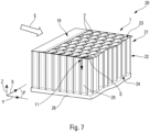
- the porous skin 1, as described above, is intended to be arranged in an acoustic attenuation panel 20, as shown in the Figure 7 .
- the acoustic attenuation panel 20 comprises an acoustic structure 21 provided, on one of these faces, with the porous skin 1.
- an “acoustic structure” designates any element having absorption properties acoustic, namely capable of trapping, dampening and/or canceling sound waves. In particular, it may be a structure based on foam or fibrous material.
- the acoustic structure 21 of the acoustic attenuation panel 20 comprises a cellular structure 22 having an upper face 23 and a lower face 24 opposite the upper face 23.
- the cellular structure 22 comprises, between the upper face 23 and the lower face 24 , alveoli 25.
- the cellular structure 22 corresponds to a honeycomb structure (or NIDA). However, in particular embodiments, it may also be other cellular structures having various shapes and arrangements of cells.
- the acoustic structure 21 also includes a rear skin 26 called reflective arranged on the lower face 24 of the cellular structure 22.
- the acoustic attenuation panel 20 is intended to be arranged, for example on a wall, by fixing the rear skin 26 on said wall.
- the acoustic structure 21 also includes the porous skin 1 which is arranged on the upper face 23 of the cellular structure 22.
- the internal face 4 of the porous skin 1 is fixed on the upper face 23 of the cellular structure 22, for example by gluing or welding.
- the porous skin 1 can in particular be fixed on the acoustic attenuation panel 20 via the support 16 ( figures 1 And 5 ).
- the porous skin 1 is arranged so that the openings 11 face the cells 25.
- the space included inside the cells 25 is accessible from the outside of the acoustic attenuation panel 20.
- the sound waves can therefore penetrate into the cells 25, as represented by the arrow S on the figure 7 , while the flow of fluid E is not able to pass through the porous skin 1.
- Such an acoustic attenuation panel 20 is particularly suitable for attenuating noise generated by an aircraft, for example a transport aircraft and in particular by a propulsion assembly (or reactor) of the aircraft.
- the acoustic attenuation panel 20 is intended to be fixed on a wall (not shown), for example an air inlet wall of a nacelle of a propulsion assembly.
- the acoustic attenuation panel 20 preferably corresponds to a flat plate, as in the example illustrated in the Figure 7 .
- the acoustic attenuation panel 20 can have varied shapes in order to match the shape of the wall on which it is intended to be arranged.
Landscapes
- Engineering & Computer Science (AREA)
- Chemical & Material Sciences (AREA)
- Combustion & Propulsion (AREA)
- Physics & Mathematics (AREA)
- Acoustics & Sound (AREA)
- Multimedia (AREA)
- Aviation & Aerospace Engineering (AREA)
- Mechanical Engineering (AREA)
- General Engineering & Computer Science (AREA)
- Soundproofing, Sound Blocking, And Sound Damping (AREA)
- Pipe Accessories (AREA)
Claims (10)
- Poröse Haut für eine Schalldämmplatte, wobei die poröse Haut (1) dazu bestimmt ist, einer Fluidströmung (E) ausgesetzt zu werden, dadurch gekennzeichnet, dass sie eine Vielzahl von Bändern (2) umfasst, die zur Fluidströmung (E) querverlaufend angeordnet sind, und die sich aufeinander folgend seitlich überlappen, wobei jedes der Fluidströmung (E) vorgelagerte Band (2) das oder die der Fluidströmung (E) nachgelagerten Bänder überlappt, dadurch, dass jedes der Bänder (2) einen ersten sogenannten vorgelagerten seitlichen Rand (7) und einen zweiten sogenannten nachgelagerten seitlichen Rand (8) umfasst, wobei mindestens einer der seitlichen Ränder (7, 8) eine Kontur umfasst, die eine Linie mit Krümmungen bildet, und dadurch, dass die Anordnung der Bänder (2) und der oder den Konturen ihrer seitlichen Ränder (7, 8) konfiguriert sind, um zwischen den Bändern (2) Öffnungen (11) anzubringen, die von einer externen Fläche der porösen Haut (1) bis zu einer internen Fläche der porösen Haut (1) miteinander verbunden sind, und zum Verhindern, dass die Fluidströmung (E) in die Öffnungen (11) eindringt.
- Poröse Haut nach Anspruch 1,
dadurch gekennzeichnet, dass mindestens einige der Öffnungen (11) durch Formen erzeugt werden, die einerseits der Kontur des nachgelagerten seitlichen Rands (8) eines ersten Bands (2B) und andererseits der Kontur des vorgelagerten seitlichen Rands (7) eines zweiten Bands (2C), dem ersten Band (2B) direkt nachgelagert, angepasst sind, wobei jede der somit erzeugten Öffnungen (11) von einem dritten Band (2A) bedeckt ist, das dem ersten Band (2B) direkt vorgelagert ist und das dieses erste Band (2B) stromabwärts überragt. - Poröse Haut nach einem der Ansprüche 1 und 2, dadurch gekennzeichnet, dass die Überlappung der Bänder (2) zwischen zwei aufeinander folgenden Bändern (2) Kontaktoberflächen (19) erzeugt, und dadurch, dass die Bänder (2) untereinander auf Höhe mindestens einiger der Kontaktoberflächen (19) befestigt sind.
- Poröse Haut nach einem der vorstehenden Ansprüche, dadurch gekennzeichnet, dass die Kontur von mindestens einem der seitlichen Ränder (7, 8) mindestens teilweise eine krummlinige Linie umfasst.
- Poröse Haut nach einem der vorstehenden Ansprüche, dadurch gekennzeichnet, dass die Kontur von mindestens einem der seitlichen Ränder (7, 8) mindestens teilweise eine unterbrochene Linie umfasst.
- Poröse Haut nach einem der Ansprüche 1 bis 5, dadurch gekennzeichnet, dass die Bänder (2) von identischer Form sind.
- Poröse Haut nach einem der Ansprüche 1 bis 5, dadurch gekennzeichnet, dass mindestens einige der Bänder (2) untereinander von unterschiedlicher Form sind.
- Poröse Haut nach einem der vorstehenden Ansprüche, dadurch gekennzeichnet, dass die Bänder (2) an mindestens einem ihrer seitlichen Ränder (7, 8) auf einer ihrer Flächen (5, 6) eine Diskontinuität (12, 14) aufweisen, die mindestens eine ebene Oberfläche (13, 15) bildet.
- Schalldämmplatte, umfassend mindestens eine akustische Struktur, die mit einer porösen Haut versehen ist, dadurch gekennzeichnet, dass die poröse Haut der akustischen Struktur (21) der porösen Haut (1) nach einem der Ansprüche 1 bis 8 entspricht.
- Schalldämmplatte nach Anspruch 9, dadurch gekennzeichnet, dass die akustische Struktur (21) mindestens eine Wabenstruktur (22) umfasst, die auf einer (24) ihrer Flächen mit einer sogenannten reflektierenden hinteren Haut (26) und auf der anderen Fläche (23) mit der porösen Haut (1) versehen ist.
Applications Claiming Priority (1)
| Application Number | Priority Date | Filing Date | Title |
|---|---|---|---|
| FR2112149A FR3129241A1 (fr) | 2021-11-17 | 2021-11-17 | Peau poreuse pourvue d’une pluralité de bandes et panneau d’atténuation acoustique comprenant une telle peau poreuse. |
Publications (2)
| Publication Number | Publication Date |
|---|---|
| EP4183994A1 EP4183994A1 (de) | 2023-05-24 |
| EP4183994B1 true EP4183994B1 (de) | 2024-08-07 |
Family
ID=79170784
Family Applications (1)
| Application Number | Title | Priority Date | Filing Date |
|---|---|---|---|
| EP22206381.0A Active EP4183994B1 (de) | 2021-11-17 | 2022-11-09 | Poröse haut mit mehreren bändern und schalldämmplatte mit solch einer porösen haut |
Country Status (4)
| Country | Link |
|---|---|
| US (1) | US12394401B2 (de) |
| EP (1) | EP4183994B1 (de) |
| CN (1) | CN116135698A (de) |
| FR (1) | FR3129241A1 (de) |
Family Cites Families (18)
| Publication number | Priority date | Publication date | Assignee | Title |
|---|---|---|---|---|
| FR2735064B1 (fr) * | 1995-06-09 | 1997-08-29 | Aerospatiale | Procede de fabrication d'une peau microporeuse en materiau composite |
| GB0016149D0 (en) * | 2000-06-30 | 2000-08-23 | Short Brothers Plc | A noise attenuation panel |
| FR2838860B1 (fr) * | 2002-04-17 | 2005-01-21 | Airbus France | Couche acoustiquement resistive multicomposant pour panneau d'attenuation acoustique et panneau ainsi obtenu |
| FR2844304B1 (fr) * | 2002-09-10 | 2004-12-10 | Airbus France | Couche acoustiquement resistive pour panneau d'attenuation acoustique, panneau utilisant une telle couche |
| FR2915522A1 (fr) * | 2007-04-30 | 2008-10-31 | Airbus France Sas | Panneau acoustique a caracteristique acoustique variable |
| US8460779B2 (en) * | 2011-03-30 | 2013-06-11 | General Electric Company | Microstructures for reducing noise of a fluid dynamic structure |
| US10240576B2 (en) * | 2015-11-25 | 2019-03-26 | General Electric Company | Wind turbine noise reduction with acoustically absorbent serrations |
| FR3054607B1 (fr) * | 2016-07-29 | 2020-02-28 | Safran Nacelles | Panneau d’attenuation acoustique pour ensemble propulsif d’aeronef et ensemble propulsif comportant un tel panneau |
| FR3069579B1 (fr) * | 2017-07-25 | 2019-08-30 | Safran Aircraft Engines | Panneau acoustique et ensemble propulsif associe |
| FR3070438B1 (fr) * | 2017-08-25 | 2020-09-11 | Safran Nacelles | Structure alveolaire et dispositif d’attenuation acoustique pour nacelle d'ensemble propulsif d'aeronef |
| US11485471B2 (en) * | 2017-08-25 | 2022-11-01 | United States Of America As Represented By The Administrator Of Nasa | Application of leading edge serration and trailing edge foam for undercarriage wheel cavity noise reduction |
| US11053888B2 (en) * | 2017-11-01 | 2021-07-06 | The Boeing Company | Fan cowl with a serrated trailing edge providing attached flow in reverse thrust mode |
| FR3074148B1 (fr) * | 2017-11-30 | 2020-11-06 | Safran Nacelles | Panneau acoustique pour nacelle de turboreacteur d’aeronef et procede de fabrication d’un element d’une nacelle |
| US20190219000A1 (en) * | 2018-01-12 | 2019-07-18 | The Boeing Company | Acoustic attenuation system for nacelle structures and method therefor |
| FR3078099B1 (fr) * | 2018-02-16 | 2020-09-11 | Safran Aircraft Engines | Structure a profil en serrations avec des surfaces traitees |
| FR3079812A1 (fr) | 2018-04-10 | 2019-10-11 | Airbus Operations | Panneau d'attenuation acoustique pour aeronef presentant des proprietes d'absorption acoustique combinees. |
| FR3088133B1 (fr) * | 2018-11-06 | 2021-06-04 | Airbus Operations Sas | Structure d’absorption acoustique comprenant des cellules avec au moins un canal annulaire, ensemble propulsif d’aeronef comprenant ladite structure |
| US11519333B2 (en) * | 2020-09-10 | 2022-12-06 | General Electric Company | Turbine engine with shockwave attenuation |
-
2021
- 2021-11-17 FR FR2112149A patent/FR3129241A1/fr not_active Ceased
-
2022
- 2022-11-09 EP EP22206381.0A patent/EP4183994B1/de active Active
- 2022-11-16 US US17/988,404 patent/US12394401B2/en active Active
- 2022-11-17 CN CN202211442192.2A patent/CN116135698A/zh active Pending
Also Published As
| Publication number | Publication date |
|---|---|
| US12394401B2 (en) | 2025-08-19 |
| FR3129241A1 (fr) | 2023-05-19 |
| EP4183994A1 (de) | 2023-05-24 |
| US20230154447A1 (en) | 2023-05-18 |
| CN116135698A (zh) | 2023-05-19 |
Similar Documents
| Publication | Publication Date | Title |
|---|---|---|
| EP3676825B1 (de) | Akustikplatte für gondel einer flugzeugantriebseinheit und zugehörige herstellungsverfahren | |
| CA2435559C (fr) | Piece tubulaire d`attenuation acoustique pour entree d`air de reacteur d`aeronef | |
| EP3489487B1 (de) | Schalldämmplatte für luftfahrzeug | |
| EP1213703B1 (de) | Akustische Platte mit Sandwichaufbau | |
| CA2441058C (fr) | Nacelle de reacteur d`aeronef a attenuation acoustique | |
| EP3993996B1 (de) | Schalldämmende beschichtung mit zellstruktur | |
| WO2017021628A1 (fr) | Structure d'atténuation acoustique à multiples degrés d'atténuation pour ensemble propulsif d'aéronef | |
| FR2971613A1 (fr) | Panneau pour le traitement acoustique comprenant une jonction entre deux parties et procede de reparation d'un panneau pour le traitement acoustique | |
| EP3534360B1 (de) | Schalldämmende beschichtung, die eine wabenstruktur mit gekrümmten zellen umfasst, die auf der einen und der anderen seite aus derselben innenwand gebildet werden | |
| CA2847668A1 (fr) | Peau intermediaire acoustique et sa mise en oeuvre | |
| EP3552951B1 (de) | Schalldämmplatte für luftfahrzeug, die kombinierte schallabsorptionseigenschaften aufweist | |
| EP4183994B1 (de) | Poröse haut mit mehreren bändern und schalldämmplatte mit solch einer porösen haut | |
| FR3143169A1 (fr) | Ame alveolaire optimisee et panneau d’attenuation acoustique la comprenant pour une turbomachine d’aeronef | |
| CA2921915C (fr) | Arriere corps de turboreacteur comportant une tuyere equipee d'un systeme d'inversion de poussee qui integre une couronne de chevrons antibruit | |
| EP3628842A1 (de) | Einheit aus zwei nebeneinander angebrachten schalldämmpaneelen, bei der die paneele eine resistive oberfläche aufweisen, die sich bis zu einer stirnwand ausdehnt | |
| FR2847866A1 (fr) | Feuille d'etancheite et d'insonorisation pour un element de carrosserie, tel qu'une porte de vehicule automobile | |
| EP2391811B1 (de) | Schallgedämpfte abgasleitung für einen turbomotor | |
| FR3019086A1 (fr) | Barettes pour drainage de panneau composite sandwich | |
| FR3164049A1 (fr) | Dispositif d’isolation acoustique pour un aéronef | |
| FR3148573A1 (fr) | Structure d’atténuation acoustique dotée de cellules en S à barrières drainées et son procédé de fabrication | |
| FR2983815A1 (fr) | Dispositif ameliore de limitation de la propagation d'ondes acoustiques au sein d'un corps creux d'un vehicule automobile tel qu'un longeron du vehicule | |
| FR2683660A1 (fr) | Structure modulaire d'absorption de vibrations, notamment acoustiques dans une enceinte close. |
Legal Events
| Date | Code | Title | Description |
|---|---|---|---|
| PUAI | Public reference made under article 153(3) epc to a published international application that has entered the european phase |
Free format text: ORIGINAL CODE: 0009012 |
|
| STAA | Information on the status of an ep patent application or granted ep patent |
Free format text: STATUS: THE APPLICATION HAS BEEN PUBLISHED |
|
| AK | Designated contracting states |
Kind code of ref document: A1 Designated state(s): AL AT BE BG CH CY CZ DE DK EE ES FI FR GB GR HR HU IE IS IT LI LT LU LV MC ME MK MT NL NO PL PT RO RS SE SI SK SM TR |
|
| STAA | Information on the status of an ep patent application or granted ep patent |
Free format text: STATUS: REQUEST FOR EXAMINATION WAS MADE |
|
| 17P | Request for examination filed |
Effective date: 20231103 |
|
| RBV | Designated contracting states (corrected) |
Designated state(s): AL AT BE BG CH CY CZ DE DK EE ES FI FR GB GR HR HU IE IS IT LI LT LU LV MC ME MK MT NL NO PL PT RO RS SE SI SK SM TR |
|
| GRAP | Despatch of communication of intention to grant a patent |
Free format text: ORIGINAL CODE: EPIDOSNIGR1 |
|
| STAA | Information on the status of an ep patent application or granted ep patent |
Free format text: STATUS: GRANT OF PATENT IS INTENDED |
|
| INTG | Intention to grant announced |
Effective date: 20240312 |
|
| GRAS | Grant fee paid |
Free format text: ORIGINAL CODE: EPIDOSNIGR3 |
|
| GRAA | (expected) grant |
Free format text: ORIGINAL CODE: 0009210 |
|
| STAA | Information on the status of an ep patent application or granted ep patent |
Free format text: STATUS: THE PATENT HAS BEEN GRANTED |
|
| AK | Designated contracting states |
Kind code of ref document: B1 Designated state(s): AL AT BE BG CH CY CZ DE DK EE ES FI FR GB GR HR HU IE IS IT LI LT LU LV MC ME MK MT NL NO PL PT RO RS SE SI SK SM TR |
|
| REG | Reference to a national code |
Ref country code: GB Ref legal event code: FG4D Free format text: NOT ENGLISH |
|
| REG | Reference to a national code |
Ref country code: CH Ref legal event code: EP |
|
| REG | Reference to a national code |
Ref country code: IE Ref legal event code: FG4D Free format text: LANGUAGE OF EP DOCUMENT: FRENCH |
|
| REG | Reference to a national code |
Ref country code: DE Ref legal event code: R096 Ref document number: 602022005157 Country of ref document: DE |
|
| REG | Reference to a national code |
Ref country code: LT Ref legal event code: MG9D |
|
| REG | Reference to a national code |
Ref country code: NL Ref legal event code: MP Effective date: 20240807 |
|
| PG25 | Lapsed in a contracting state [announced via postgrant information from national office to epo] |
Ref country code: NO Free format text: LAPSE BECAUSE OF FAILURE TO SUBMIT A TRANSLATION OF THE DESCRIPTION OR TO PAY THE FEE WITHIN THE PRESCRIBED TIME-LIMIT Effective date: 20241107 |
|
| REG | Reference to a national code |
Ref country code: AT Ref legal event code: MK05 Ref document number: 1711168 Country of ref document: AT Kind code of ref document: T Effective date: 20240807 |
|
| PG25 | Lapsed in a contracting state [announced via postgrant information from national office to epo] |
Ref country code: FI Free format text: LAPSE BECAUSE OF FAILURE TO SUBMIT A TRANSLATION OF THE DESCRIPTION OR TO PAY THE FEE WITHIN THE PRESCRIBED TIME-LIMIT Effective date: 20240807 Ref country code: NL Free format text: LAPSE BECAUSE OF FAILURE TO SUBMIT A TRANSLATION OF THE DESCRIPTION OR TO PAY THE FEE WITHIN THE PRESCRIBED TIME-LIMIT Effective date: 20240807 Ref country code: PL Free format text: LAPSE BECAUSE OF FAILURE TO SUBMIT A TRANSLATION OF THE DESCRIPTION OR TO PAY THE FEE WITHIN THE PRESCRIBED TIME-LIMIT Effective date: 20240807 Ref country code: GR Free format text: LAPSE BECAUSE OF FAILURE TO SUBMIT A TRANSLATION OF THE DESCRIPTION OR TO PAY THE FEE WITHIN THE PRESCRIBED TIME-LIMIT Effective date: 20241108 Ref country code: PT Free format text: LAPSE BECAUSE OF FAILURE TO SUBMIT A TRANSLATION OF THE DESCRIPTION OR TO PAY THE FEE WITHIN THE PRESCRIBED TIME-LIMIT Effective date: 20241209 |
|
| PG25 | Lapsed in a contracting state [announced via postgrant information from national office to epo] |
Ref country code: BG Free format text: LAPSE BECAUSE OF FAILURE TO SUBMIT A TRANSLATION OF THE DESCRIPTION OR TO PAY THE FEE WITHIN THE PRESCRIBED TIME-LIMIT Effective date: 20240807 |
|
| PG25 | Lapsed in a contracting state [announced via postgrant information from national office to epo] |
Ref country code: LV Free format text: LAPSE BECAUSE OF FAILURE TO SUBMIT A TRANSLATION OF THE DESCRIPTION OR TO PAY THE FEE WITHIN THE PRESCRIBED TIME-LIMIT Effective date: 20240807 |
|
| PG25 | Lapsed in a contracting state [announced via postgrant information from national office to epo] |
Ref country code: AT Free format text: LAPSE BECAUSE OF FAILURE TO SUBMIT A TRANSLATION OF THE DESCRIPTION OR TO PAY THE FEE WITHIN THE PRESCRIBED TIME-LIMIT Effective date: 20240807 Ref country code: IS Free format text: LAPSE BECAUSE OF FAILURE TO SUBMIT A TRANSLATION OF THE DESCRIPTION OR TO PAY THE FEE WITHIN THE PRESCRIBED TIME-LIMIT Effective date: 20241207 |
|
| PG25 | Lapsed in a contracting state [announced via postgrant information from national office to epo] |
Ref country code: HR Free format text: LAPSE BECAUSE OF FAILURE TO SUBMIT A TRANSLATION OF THE DESCRIPTION OR TO PAY THE FEE WITHIN THE PRESCRIBED TIME-LIMIT Effective date: 20240807 |
|
| PG25 | Lapsed in a contracting state [announced via postgrant information from national office to epo] |
Ref country code: RS Free format text: LAPSE BECAUSE OF FAILURE TO SUBMIT A TRANSLATION OF THE DESCRIPTION OR TO PAY THE FEE WITHIN THE PRESCRIBED TIME-LIMIT Effective date: 20241107 Ref country code: ES Free format text: LAPSE BECAUSE OF FAILURE TO SUBMIT A TRANSLATION OF THE DESCRIPTION OR TO PAY THE FEE WITHIN THE PRESCRIBED TIME-LIMIT Effective date: 20240807 |
|
| PG25 | Lapsed in a contracting state [announced via postgrant information from national office to epo] |
Ref country code: RS Free format text: LAPSE BECAUSE OF FAILURE TO SUBMIT A TRANSLATION OF THE DESCRIPTION OR TO PAY THE FEE WITHIN THE PRESCRIBED TIME-LIMIT Effective date: 20241107 Ref country code: PT Free format text: LAPSE BECAUSE OF FAILURE TO SUBMIT A TRANSLATION OF THE DESCRIPTION OR TO PAY THE FEE WITHIN THE PRESCRIBED TIME-LIMIT Effective date: 20241209 Ref country code: PL Free format text: LAPSE BECAUSE OF FAILURE TO SUBMIT A TRANSLATION OF THE DESCRIPTION OR TO PAY THE FEE WITHIN THE PRESCRIBED TIME-LIMIT Effective date: 20240807 Ref country code: NO Free format text: LAPSE BECAUSE OF FAILURE TO SUBMIT A TRANSLATION OF THE DESCRIPTION OR TO PAY THE FEE WITHIN THE PRESCRIBED TIME-LIMIT Effective date: 20241107 Ref country code: NL Free format text: LAPSE BECAUSE OF FAILURE TO SUBMIT A TRANSLATION OF THE DESCRIPTION OR TO PAY THE FEE WITHIN THE PRESCRIBED TIME-LIMIT Effective date: 20240807 Ref country code: LV Free format text: LAPSE BECAUSE OF FAILURE TO SUBMIT A TRANSLATION OF THE DESCRIPTION OR TO PAY THE FEE WITHIN THE PRESCRIBED TIME-LIMIT Effective date: 20240807 Ref country code: IS Free format text: LAPSE BECAUSE OF FAILURE TO SUBMIT A TRANSLATION OF THE DESCRIPTION OR TO PAY THE FEE WITHIN THE PRESCRIBED TIME-LIMIT Effective date: 20241207 Ref country code: HR Free format text: LAPSE BECAUSE OF FAILURE TO SUBMIT A TRANSLATION OF THE DESCRIPTION OR TO PAY THE FEE WITHIN THE PRESCRIBED TIME-LIMIT Effective date: 20240807 Ref country code: GR Free format text: LAPSE BECAUSE OF FAILURE TO SUBMIT A TRANSLATION OF THE DESCRIPTION OR TO PAY THE FEE WITHIN THE PRESCRIBED TIME-LIMIT Effective date: 20241108 Ref country code: FI Free format text: LAPSE BECAUSE OF FAILURE TO SUBMIT A TRANSLATION OF THE DESCRIPTION OR TO PAY THE FEE WITHIN THE PRESCRIBED TIME-LIMIT Effective date: 20240807 Ref country code: ES Free format text: LAPSE BECAUSE OF FAILURE TO SUBMIT A TRANSLATION OF THE DESCRIPTION OR TO PAY THE FEE WITHIN THE PRESCRIBED TIME-LIMIT Effective date: 20240807 Ref country code: BG Free format text: LAPSE BECAUSE OF FAILURE TO SUBMIT A TRANSLATION OF THE DESCRIPTION OR TO PAY THE FEE WITHIN THE PRESCRIBED TIME-LIMIT Effective date: 20240807 Ref country code: AT Free format text: LAPSE BECAUSE OF FAILURE TO SUBMIT A TRANSLATION OF THE DESCRIPTION OR TO PAY THE FEE WITHIN THE PRESCRIBED TIME-LIMIT Effective date: 20240807 |
|
| PG25 | Lapsed in a contracting state [announced via postgrant information from national office to epo] |
Ref country code: DK Free format text: LAPSE BECAUSE OF FAILURE TO SUBMIT A TRANSLATION OF THE DESCRIPTION OR TO PAY THE FEE WITHIN THE PRESCRIBED TIME-LIMIT Effective date: 20240807 Ref country code: SM Free format text: LAPSE BECAUSE OF FAILURE TO SUBMIT A TRANSLATION OF THE DESCRIPTION OR TO PAY THE FEE WITHIN THE PRESCRIBED TIME-LIMIT Effective date: 20240807 |
|
| PG25 | Lapsed in a contracting state [announced via postgrant information from national office to epo] |
Ref country code: EE Free format text: LAPSE BECAUSE OF FAILURE TO SUBMIT A TRANSLATION OF THE DESCRIPTION OR TO PAY THE FEE WITHIN THE PRESCRIBED TIME-LIMIT Effective date: 20240807 |
|
| PG25 | Lapsed in a contracting state [announced via postgrant information from national office to epo] |
Ref country code: CZ Free format text: LAPSE BECAUSE OF FAILURE TO SUBMIT A TRANSLATION OF THE DESCRIPTION OR TO PAY THE FEE WITHIN THE PRESCRIBED TIME-LIMIT Effective date: 20240807 |
|
| PG25 | Lapsed in a contracting state [announced via postgrant information from national office to epo] |
Ref country code: SK Free format text: LAPSE BECAUSE OF FAILURE TO SUBMIT A TRANSLATION OF THE DESCRIPTION OR TO PAY THE FEE WITHIN THE PRESCRIBED TIME-LIMIT Effective date: 20240807 |
|
| REG | Reference to a national code |
Ref country code: DE Ref legal event code: R097 Ref document number: 602022005157 Country of ref document: DE |
|
| PLBE | No opposition filed within time limit |
Free format text: ORIGINAL CODE: 0009261 |
|
| STAA | Information on the status of an ep patent application or granted ep patent |
Free format text: STATUS: NO OPPOSITION FILED WITHIN TIME LIMIT |
|
| PG25 | Lapsed in a contracting state [announced via postgrant information from national office to epo] |
Ref country code: MC Free format text: LAPSE BECAUSE OF FAILURE TO SUBMIT A TRANSLATION OF THE DESCRIPTION OR TO PAY THE FEE WITHIN THE PRESCRIBED TIME-LIMIT Effective date: 20240807 |
|
| PG25 | Lapsed in a contracting state [announced via postgrant information from national office to epo] |
Ref country code: LU Free format text: LAPSE BECAUSE OF NON-PAYMENT OF DUE FEES Effective date: 20241109 |
|
| 26N | No opposition filed |
Effective date: 20250508 |
|
| REG | Reference to a national code |
Ref country code: BE Ref legal event code: MM Effective date: 20241130 |
|
| PG25 | Lapsed in a contracting state [announced via postgrant information from national office to epo] |
Ref country code: SE Free format text: LAPSE BECAUSE OF FAILURE TO SUBMIT A TRANSLATION OF THE DESCRIPTION OR TO PAY THE FEE WITHIN THE PRESCRIBED TIME-LIMIT Effective date: 20240807 |
|
| PG25 | Lapsed in a contracting state [announced via postgrant information from national office to epo] |
Ref country code: BE Free format text: LAPSE BECAUSE OF NON-PAYMENT OF DUE FEES Effective date: 20241130 |
|
| PG25 | Lapsed in a contracting state [announced via postgrant information from national office to epo] |
Ref country code: IE Free format text: LAPSE BECAUSE OF NON-PAYMENT OF DUE FEES Effective date: 20241109 |
|
| PG25 | Lapsed in a contracting state [announced via postgrant information from national office to epo] |
Ref country code: RO Free format text: LAPSE BECAUSE OF FAILURE TO SUBMIT A TRANSLATION OF THE DESCRIPTION OR TO PAY THE FEE WITHIN THE PRESCRIBED TIME-LIMIT Effective date: 20240807 |
|
| PGFP | Annual fee paid to national office [announced via postgrant information from national office to epo] |
Ref country code: DE Payment date: 20251119 Year of fee payment: 4 |
|
| PGFP | Annual fee paid to national office [announced via postgrant information from national office to epo] |
Ref country code: FR Payment date: 20251126 Year of fee payment: 4 |
|
| PG25 | Lapsed in a contracting state [announced via postgrant information from national office to epo] |
Ref country code: IT Free format text: LAPSE BECAUSE OF FAILURE TO SUBMIT A TRANSLATION OF THE DESCRIPTION OR TO PAY THE FEE WITHIN THE PRESCRIBED TIME-LIMIT Effective date: 20240807 |
|
| PG25 | Lapsed in a contracting state [announced via postgrant information from national office to epo] |
Ref country code: HU Free format text: LAPSE BECAUSE OF FAILURE TO SUBMIT A TRANSLATION OF THE DESCRIPTION OR TO PAY THE FEE WITHIN THE PRESCRIBED TIME-LIMIT; INVALID AB INITIO Effective date: 20221109 |
|
| PG25 | Lapsed in a contracting state [announced via postgrant information from national office to epo] |
Ref country code: CY Free format text: LAPSE BECAUSE OF FAILURE TO SUBMIT A TRANSLATION OF THE DESCRIPTION OR TO PAY THE FEE WITHIN THE PRESCRIBED TIME-LIMIT; INVALID AB INITIO Effective date: 20221109 |