EP4183995A2 - Soupape à débit limité hydraulique - Google Patents
Soupape à débit limité hydraulique Download PDFInfo
- Publication number
- EP4183995A2 EP4183995A2 EP22208919.5A EP22208919A EP4183995A2 EP 4183995 A2 EP4183995 A2 EP 4183995A2 EP 22208919 A EP22208919 A EP 22208919A EP 4183995 A2 EP4183995 A2 EP 4183995A2
- Authority
- EP
- European Patent Office
- Prior art keywords
- fluid
- emid
- chamber
- source
- line
- Prior art date
- Legal status (The legal status is an assumption and is not a legal conclusion. Google has not performed a legal analysis and makes no representation as to the accuracy of the status listed.)
- Granted
Links
Images


Classifications
-
- F—MECHANICAL ENGINEERING; LIGHTING; HEATING; WEAPONS; BLASTING
- F02—COMBUSTION ENGINES; HOT-GAS OR COMBUSTION-PRODUCT ENGINE PLANTS
- F02C—GAS-TURBINE PLANTS; AIR INTAKES FOR JET-PROPULSION PLANTS; CONTROLLING FUEL SUPPLY IN AIR-BREATHING JET-PROPULSION PLANTS
- F02C7/00—Features, components parts, details or accessories, not provided for in, or of interest apart form groups F02C1/00 - F02C6/00; Air intakes for jet-propulsion plants
- F02C7/22—Fuel supply systems
- F02C7/232—Fuel valves; Draining valves or systems
-
- F—MECHANICAL ENGINEERING; LIGHTING; HEATING; WEAPONS; BLASTING
- F02—COMBUSTION ENGINES; HOT-GAS OR COMBUSTION-PRODUCT ENGINE PLANTS
- F02C—GAS-TURBINE PLANTS; AIR INTAKES FOR JET-PROPULSION PLANTS; CONTROLLING FUEL SUPPLY IN AIR-BREATHING JET-PROPULSION PLANTS
- F02C3/00—Gas-turbine plants characterised by the use of combustion products as the working fluid
-
- F—MECHANICAL ENGINEERING; LIGHTING; HEATING; WEAPONS; BLASTING
- F02—COMBUSTION ENGINES; HOT-GAS OR COMBUSTION-PRODUCT ENGINE PLANTS
- F02C—GAS-TURBINE PLANTS; AIR INTAKES FOR JET-PROPULSION PLANTS; CONTROLLING FUEL SUPPLY IN AIR-BREATHING JET-PROPULSION PLANTS
- F02C9/00—Controlling gas-turbine plants; Controlling fuel supply in air- breathing jet-propulsion plants
- F02C9/26—Control of fuel supply
- F02C9/263—Control of fuel supply by means of fuel metering valves
-
- F—MECHANICAL ENGINEERING; LIGHTING; HEATING; WEAPONS; BLASTING
- F05—INDEXING SCHEMES RELATING TO ENGINES OR PUMPS IN VARIOUS SUBCLASSES OF CLASSES F01-F04
- F05D—INDEXING SCHEME FOR ASPECTS RELATING TO NON-POSITIVE-DISPLACEMENT MACHINES OR ENGINES, GAS-TURBINES OR JET-PROPULSION PLANTS
- F05D2220/00—Application
- F05D2220/30—Application in turbines
- F05D2220/32—Application in turbines in gas turbines
-
- F—MECHANICAL ENGINEERING; LIGHTING; HEATING; WEAPONS; BLASTING
- F05—INDEXING SCHEMES RELATING TO ENGINES OR PUMPS IN VARIOUS SUBCLASSES OF CLASSES F01-F04
- F05D—INDEXING SCHEME FOR ASPECTS RELATING TO NON-POSITIVE-DISPLACEMENT MACHINES OR ENGINES, GAS-TURBINES OR JET-PROPULSION PLANTS
- F05D2240/00—Components
- F05D2240/35—Combustors or associated equipment
Definitions
- This application relates to a valve and an electromechanical interface device (EMID) for use with a variable pressure supply.
- EMID electromechanical interface device
- Valves are used in any number of applications.
- a metering valve is incorporated into a fuel supply system for supplying fuel to a combustor nozzle on a gas turbine engine.
- EMIDS such as electrohydraulic servo valves (EHSV) are also used in many applications.
- EHSV electrohydraulic servo valves
- an EHSV is incorporated to control hydraulic fluid flow to control the position of a metering valve.
- a fluid flow system includes a main valve having a spool, a first chamber, and a second chamber. A pressure difference between the first chamber and the second chamber is configured to move the spool to control fluid flow.
- An electromechanical interface device (EMID) is in fluid communication with at least one of the first and second chambers of the main valve. The EMID is configured to meter fluid from a first source and a second source to the at least one of the first chamber and the second chamber. The first source has a different pressure from the second source.
- a fixed orifice is arranged between the main valve and the EMID.
- a fuel system for a gas turbine engine is also disclosed.
- a fluid flow system 28 is illustrated in Figure 1 .
- the fluid flow system 28 may be used to meter fuel to a nozzle 26 on an engine 11, for example.
- the engine 11 may be a gas turbine engine, for example.
- Gas turbine engines are known, and may generally include a fan section, a compressor section, a combustor section and a turbine section, among other components.
- the nozzle 26 may be a nozzle 26 into a combustor section.
- the fluid flow system 28 may be utilized for applications other than fuel supply.
- the fluid flow system 28 generally includes an electromechanical interface device (EMID) 16 and a metering valve 22.
- the EMID 16 may be an electrohydraulic servo valve (EHSV), torque motor, or other device, for example.
- the EMID 16 and metering valve 22 control fluid to the nozzle 26 from a variable pressure source.
- a first fluid source 10 and a second fluid source 12 are in communication with the EMID 16 and then the metering valve 22.
- fluid from the first fluid source 10 also flows to the metering valve 22 to be delivered to nozzle 26.
- the first fluid source 10 is a high-pressure fluid source and the second fluid source 12 is a low-pressure fluid source.
- a pump 13, 15 at each of the first and second fluid sources 10, 12, respectively, supplies the fluid to the system 28.
- each source 10 and 12 are fuel.
- additional fluid flow lines 23, 24 connect the first source 10 to the EMID 16 and the metering valve 22.
- Fluid flow line 24 connects the first source 10 and the inlet port 27 of the metering valve 22.
- Fluid flow line 23 connects the first source 10 and the EMID 16.
- a fluid line 25 connects the metering valve 22 to the fuel nozzle 26.
- the EMID 16 is in fluid communication with the metering valve 22 via two fluid lines 18, 20.
- the EMID 16 modulates fluid from the high-pressure source 10 and the low-pressure source 12 to achieve a pressure differential to the metering valve 22.
- An electronic control 50 shown schematically, selectively controls the EHSV 16.
- the first fluid line 18 is in communication with a first chamber 37 at a first end 40 of the metering valve 22.
- the second fluid line 20 is in communication with a second chamber 34 at a second end 42 of the metering valve 22.
- the metering valve 22 also includes a spool 38 arranged between the first and second chambers 37, 34.
- An annulus 39 is defined about the spool 38.
- the annulus 39 is in communication with an inlet port 27 and an outlet port 29.
- a pressure difference between the first and second chambers 37, 34 moves the spool 38, which meters fluid between the inlet and outlet ports 27, 29 by blocking portions of the inlet and/or outlet ports 27, 29.
- the speed at which the spool 38 moves based on the pressure differences between the chambers 37, 34 is known as the slew rate.
- Hydraulic control of a metering valve 22 through an EMID 16 is dependent upon the pressure within the system 28.
- the slew rate of the metering valve 22 will increase as the pressure differential between lines 18 and 20 is increased.
- the EHSV 16 controls the pressure acting on either end of the metering valve 22 to achieve a desired position for spool 38.
- the slew rate may increase. It is undesirable for the slew rate to exceed a predetermined threshold. To prevent the pressure differences that cause a slew rate above the predetermined threshold, fixed orifices 19 and 20 may be arranged between the EMID 16 and the metering valve 22.
- a first fixed orifice 19 is arranged along the first fluid line 18 and a second fixed orifice 21 is arranged along the second fluid line 20.
- the fixed orifices 19, 21 are arranged between the EMID 16 and metering valve 22 to limit the flow rate of fuel to the metering valve 22.
- the fixed rate orifices 19, 21 are sized to maintain the flow of fluid within a predetermined pressure range. For example, there may be a predetermined threshold flow rate that is a maximum flow rate and the orifices 19, 21 are sized to ensure the pressure difference between the first chamber 37 and the second chamber 34 remains below the predetermined threshold. This maintains the slew rate below the predetermined maximum.
- FIG. 2 shows an example EMID 16.
- the EMID 16 is an electrohydraulic servo valve (EHSV).
- the EHSV 16 has two stages including a torque motor 30 and a hydraulic mechanism 300 used to drive a spool 55 of a spool valve 41.
- the torque motor 30 controls the flow of hydraulic fluid which drives the hydraulic mechanism 300 and the spool 55.
- the torque motor 30 includes an armature 32 and magnetic coils 36.
- the armature 32 is positioned by the magnetic force from the energized coils 36 to provide a supply pressure 35 to position the hydraulic mechanism 300.
- the hydraulic mechanism 300 attached to the torque motor 30 may be a jet type, or any other type of hydraulic mechanism.
- the spool 55 has a right spool valve land 58 and a left spool valve land 56 on a spool 55.
- the right spool valve land 58 controls communication with the second fluid line 20 and the left spool valve land 56 controls communication with the first fluid line 18.
- the spool 55 moves in response to fluid pressure in a left spool chamber 52 and a right spool chamber 54.
- End lands 57 provide reaction surfaces for fluid in chambers 52 and 54.
- Source 10 is directed into chambers between end lands 57 and each of lands 56 and 58.
- Source 12 is directed into a chamber between lands 56 and 58.
- Electronic control 50 positions spool 55 such that a desired mix from sources 10 and 12 passes into lines 18 and 20, to in turn achieve a desired position of the spool 38 in metering valve 22. This provides a desired flow of fuel through metering valve.
- FIG 3 illustrates another example of a fluid flow system 128.
- the fluid flow system 128 corresponds to the fluid flow system 28 of Figures 1 and 2 , with like parts having reference numerals pre-appended with a "1.”
- the EMID 116 in the system 128 is a single stage servo valve (SSSV) 116.
- the SSSV 116 is in communication with a high pressure source 110 and a low pressure source 112.
- the SSSV 116 includes a flapper 133 that moves in response to current through a torque motor 130. Fluid flowing through the flapper 133 flows from the fluid sources 110, 112 to the first fluid line 118 and then to the metering valve 122.
- Electronic control 150 controls the torque motor 130 to achieve a desired mix between lines 110 and 112 into line 118.
- the fluid line 118 connects the SSSV 116 to a first chamber 137 of the metering valve 122.
- a second chamber 134 is in communication with the second fluid source 112.
- a third chamber 135 is in communication with source 112.
- a fluid pressure difference between the first and third chambers 134, 135 in combination acts against a mixed flow from line 118 in chamber 137. This moves the spool 138 to modulate fluid flowing to the nozzle 136 through line 126.
- an annulus 139 selectively controls flow between inlet line 124, from source 110, and to outlet line 126.
- Control 150 controls the mixed pressure on line 118 to position spool 138.
- the fixed orifice 119 limits the slew rate of the metering valve 122 by preventing large pressure differences between the chambers 134/135 and 137.
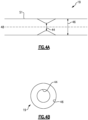
- Figure 4A shows an example orifice 19.
- the example orifice 19 is shown, this description may also apply to the orifice 21 in Figure 1 and orifice 119 in Figure 3 .
- the orifice 19 is arranged along a pipe 51 and maintains valve slew rates at the metering valve 22 below a predetermined threshold.
- the orifice 19 has an inner diameter 44 that is smaller than a nominal diameter 46 of the pipe 51.
- the orifice 19 extends inward of the pipe 51 and is symmetric about the longitudinal axis 48 of the pipe 51. In other words, the orifice 19 extends into the pipe 51 about a circumference of the pipe 51.
- This configuration limits the slew rates during a failed EMID 16 condition by limiting the pressure of fluid flowing to the metering valve.
- a particular orifice 19 is shown, other orifice configurations may be used.
- the diameters 44, 46 may be selected based on a particular application to maintain the slew rate below a predetermined threshold.
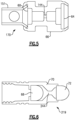
- Figure 5 shows another example orifice 170.
- the orifice 170 is arranged within a housing 66.
- a first screen 60 and a second screen 64 are arranged on opposite sides of restriction 144.
- the screens 60, 64 protect the restriction 144 from debris in the fluid.
- Figure 6 shows another example orifice 219.
- the orifice 219 includes a housing 70.
- a first screen 68 and a second screen 72 are arranged on opposite sides of the restriction 244.
- the disclosed system eliminates concerns about undesirably high slew rates with a simple construction using fixed orifices to maintain the valve slew rates within a safe range. This arrangement limits the slew rates when the EMID fails. This arrangement may reduce cost and weight and improve reliability of the fuel metering system.
- metering valve in a fuel supply
- actuators for other functions on an engine, such as for variable vane stator actuators, pneumatic valves, bleed valves, or other applications.
- a fluid flow system under this disclosure could be said to include a metering valve having a spool, a first chamber, and a second chamber. A pressure difference between the first chamber and the second chamber is configured to move the spool to meter a fluid.
- the metering valve is in fluid communication with a use.
- An electromechanical meter interface device (EMID) is in fluid communication with at least one of the first and second chambers of the metering valve.
- the EMID is configured to meter fluid from a first source and a second source to at least one of the first chamber and the second chamber.
- the first source has a different pressure from the second source.
- At least one fixed orifice is arranged between the metering valve and the EMID.
- the first chamber may be in communication with the EMID via a first fluid line and the second chamber is in communication with the EMID via a second fluid line.
- the at least one fixed orifice includes a pair of fixed orifices, with one of the fixed orifices on the first fluid line and one on the second fluid line.
- one of the first and second chambers may be is in fluid communication with the EMID via a first line, and the other of the first and second chambers is in fluid communication with one of the first and second sources without passing through the EMID, and the fixed orifice is on the first line.
- a fluid flow system under this disclosure could also be said to include a metering means for metering fluid flow from a fluid source to a use.
- Control valve means direct a fluid source mixed from a first fluid source and a second fluid source through a first line to control a volume of fluid metered by the metering means.
- Fixed restriction means on the first line limit a pressure from the control valve means reaching the metering means.
- the metering means may be a spool valve.
- the control valve means may be an electromechanical interface device and the fluid restrictions means may be a fixed orifice.
Landscapes
- Engineering & Computer Science (AREA)
- Chemical & Material Sciences (AREA)
- Combustion & Propulsion (AREA)
- Mechanical Engineering (AREA)
- General Engineering & Computer Science (AREA)
- Magnetically Actuated Valves (AREA)
- Measuring Volume Flow (AREA)
- Physics & Mathematics (AREA)
- General Physics & Mathematics (AREA)
- Automation & Control Theory (AREA)
Applications Claiming Priority (1)
| Application Number | Priority Date | Filing Date | Title |
|---|---|---|---|
| US17/533,668 US11746710B2 (en) | 2021-11-23 | 2021-11-23 | Hydraulically rate limited valve |
Publications (3)
| Publication Number | Publication Date |
|---|---|
| EP4183995A2 true EP4183995A2 (fr) | 2023-05-24 |
| EP4183995A3 EP4183995A3 (fr) | 2023-08-16 |
| EP4183995B1 EP4183995B1 (fr) | 2025-01-01 |
Family
ID=84361135
Family Applications (1)
| Application Number | Title | Priority Date | Filing Date |
|---|---|---|---|
| EP22208919.5A Active EP4183995B1 (fr) | 2021-11-23 | 2022-11-22 | Soupape à débit limité hydraulique |
Country Status (2)
| Country | Link |
|---|---|
| US (1) | US11746710B2 (fr) |
| EP (1) | EP4183995B1 (fr) |
Family Cites Families (11)
| Publication number | Priority date | Publication date | Assignee | Title |
|---|---|---|---|---|
| US4530487A (en) * | 1984-03-16 | 1985-07-23 | Tew Sydney K | Direct drive servovalve and fuel control system incorporating same |
| GB9022387D0 (en) * | 1990-10-16 | 1990-11-28 | Lucas Ind Plc | Fuel control system for a gas turbine engine |
| US6981359B2 (en) | 2003-06-16 | 2006-01-03 | Woodward Governor Company | Centrifugal pump fuel system and method for gas turbine engine |
| US7114525B2 (en) * | 2003-08-29 | 2006-10-03 | Dana Corporation | Method and apparatus for reduction of fluid-borne noise in hydraulic systems |
| EP1819914A2 (fr) * | 2004-11-19 | 2007-08-22 | Goodrich Pump & Engine Control Systems, Inc. | Pompe a combustibles a deux etages pour turbines a gaz |
| US7565793B2 (en) * | 2006-02-27 | 2009-07-28 | Honeywell International Inc. | Gas turbine engine fuel control system having start / back up check valve (SBUC) providing a main fuel check valve function |
| US7836676B2 (en) | 2007-06-04 | 2010-11-23 | Honeywell International Inc. | Fuel metering valve back-up position control system |
| US9068509B2 (en) | 2010-09-08 | 2015-06-30 | Honeywell International Inc. | Gas turbine engine fuel control thrust control override system |
| GB201117160D0 (en) * | 2011-10-05 | 2011-11-16 | Rolls Royce Goodrich Engine Control Systems Ltd | Fuel system |
| US8951021B2 (en) * | 2013-01-18 | 2015-02-10 | General Electric Company | Dual pump/dual bypass fuel pumping system |
| US11378018B2 (en) * | 2020-06-11 | 2022-07-05 | Honeywell International Inc. | Fuel metering system |
-
2021
- 2021-11-23 US US17/533,668 patent/US11746710B2/en active Active
-
2022
- 2022-11-22 EP EP22208919.5A patent/EP4183995B1/fr active Active
Also Published As
| Publication number | Publication date |
|---|---|
| US11746710B2 (en) | 2023-09-05 |
| US20230160349A1 (en) | 2023-05-25 |
| EP4183995B1 (fr) | 2025-01-01 |
| EP4183995A3 (fr) | 2023-08-16 |
Similar Documents
| Publication | Publication Date | Title |
|---|---|---|
| EP1295021B1 (fr) | Procede et appareil pour assurer l'arret, la protection contre la survitesse et la commande directionnelle d'un courant en derivation dans un systeme de distribution de carburant | |
| US6981359B2 (en) | Centrifugal pump fuel system and method for gas turbine engine | |
| EP2744996B1 (fr) | Unité de commande séparée | |
| US9957891B2 (en) | Fuel manifold cooling flow recirculation | |
| EP2063087B1 (fr) | Dispositif d'alimentation étagée de carburant | |
| US7836676B2 (en) | Fuel metering valve back-up position control system | |
| EP2339147B1 (fr) | Système de commande d'alimentation en carburant d'un moteur d'aéronef | |
| EP2497923B1 (fr) | Système de carburant | |
| EP4063633B1 (fr) | Système d'alimentation en carburant doté d'un compteur de mesure et d'une soupape d'arrêt d'urgence | |
| US9243565B2 (en) | Gas turbine engine fuel system metering valve | |
| US9068511B2 (en) | Pressure regulating valve | |
| EP3081784B1 (fr) | Systeme de commande de carburant avec element d'arret pour turbine a gaz et methode | |
| US9140190B2 (en) | Gas turbine engine fuel metering valve adapted to selectively receive fuel flow increase/decrease commands from the engine control and from the back-up fuel control | |
| EP4183995A2 (fr) | Soupape à débit limité hydraulique | |
| CN121773262A (zh) | 歧管选择计量系统 | |
| EP4413243B1 (fr) | Régulateur de débit constant | |
| CN119860297B (zh) | 燃油调节器及燃油调节方法 | |
| EP4273387B1 (fr) | Système de carburant d'aéronef avec soupape à pression minimale | |
| EP4495425B1 (fr) | Soupapes combinees de decharge et de derivation haute pression | |
| EP4269769A1 (fr) | Système d'arrêt rapide de carburant avec verrouillage |
Legal Events
| Date | Code | Title | Description |
|---|---|---|---|
| PUAI | Public reference made under article 153(3) epc to a published international application that has entered the european phase |
Free format text: ORIGINAL CODE: 0009012 |
|
| STAA | Information on the status of an ep patent application or granted ep patent |
Free format text: STATUS: THE APPLICATION HAS BEEN PUBLISHED |
|
| AK | Designated contracting states |
Kind code of ref document: A2 Designated state(s): AL AT BE BG CH CY CZ DE DK EE ES FI FR GB GR HR HU IE IS IT LI LT LU LV MC ME MK MT NL NO PL PT RO RS SE SI SK SM TR |
|
| PUAL | Search report despatched |
Free format text: ORIGINAL CODE: 0009013 |
|
| AK | Designated contracting states |
Kind code of ref document: A3 Designated state(s): AL AT BE BG CH CY CZ DE DK EE ES FI FR GB GR HR HU IE IS IT LI LT LU LV MC ME MK MT NL NO PL PT RO RS SE SI SK SM TR |
|
| RIC1 | Information provided on ipc code assigned before grant |
Ipc: F02C 9/26 20060101ALI20230707BHEP Ipc: F02C 7/232 20060101AFI20230707BHEP |
|
| STAA | Information on the status of an ep patent application or granted ep patent |
Free format text: STATUS: REQUEST FOR EXAMINATION WAS MADE |
|
| 17P | Request for examination filed |
Effective date: 20240216 |
|
| RBV | Designated contracting states (corrected) |
Designated state(s): AL AT BE BG CH CY CZ DE DK EE ES FI FR GB GR HR HU IE IS IT LI LT LU LV MC ME MK MT NL NO PL PT RO RS SE SI SK SM TR |
|
| GRAP | Despatch of communication of intention to grant a patent |
Free format text: ORIGINAL CODE: EPIDOSNIGR1 |
|
| STAA | Information on the status of an ep patent application or granted ep patent |
Free format text: STATUS: GRANT OF PATENT IS INTENDED |
|
| INTG | Intention to grant announced |
Effective date: 20240906 |
|
| GRAS | Grant fee paid |
Free format text: ORIGINAL CODE: EPIDOSNIGR3 |
|
| GRAA | (expected) grant |
Free format text: ORIGINAL CODE: 0009210 |
|
| STAA | Information on the status of an ep patent application or granted ep patent |
Free format text: STATUS: THE PATENT HAS BEEN GRANTED |
|
| AK | Designated contracting states |
Kind code of ref document: B1 Designated state(s): AL AT BE BG CH CY CZ DE DK EE ES FI FR GB GR HR HU IE IS IT LI LT LU LV MC ME MK MT NL NO PL PT RO RS SE SI SK SM TR |
|
| REG | Reference to a national code |
Ref country code: GB Ref legal event code: FG4D |
|
| REG | Reference to a national code |
Ref country code: CH Ref legal event code: EP |
|
| REG | Reference to a national code |
Ref country code: DE Ref legal event code: R096 Ref document number: 602022009324 Country of ref document: DE |
|
| REG | Reference to a national code |
Ref country code: IE Ref legal event code: FG4D |
|
| REG | Reference to a national code |
Ref country code: LT Ref legal event code: MG9D |
|
| REG | Reference to a national code |
Ref country code: NL Ref legal event code: MP Effective date: 20250101 |
|
| REG | Reference to a national code |
Ref country code: AT Ref legal event code: MK05 Ref document number: 1756464 Country of ref document: AT Kind code of ref document: T Effective date: 20250101 |
|
| PG25 | Lapsed in a contracting state [announced via postgrant information from national office to epo] |
Ref country code: NL Free format text: LAPSE BECAUSE OF FAILURE TO SUBMIT A TRANSLATION OF THE DESCRIPTION OR TO PAY THE FEE WITHIN THE PRESCRIBED TIME-LIMIT Effective date: 20250101 |
|
| PG25 | Lapsed in a contracting state [announced via postgrant information from national office to epo] |
Ref country code: FI Free format text: LAPSE BECAUSE OF FAILURE TO SUBMIT A TRANSLATION OF THE DESCRIPTION OR TO PAY THE FEE WITHIN THE PRESCRIBED TIME-LIMIT Effective date: 20250101 |
|
| PG25 | Lapsed in a contracting state [announced via postgrant information from national office to epo] |
Ref country code: PL Free format text: LAPSE BECAUSE OF FAILURE TO SUBMIT A TRANSLATION OF THE DESCRIPTION OR TO PAY THE FEE WITHIN THE PRESCRIBED TIME-LIMIT Effective date: 20250101 |
|
| PG25 | Lapsed in a contracting state [announced via postgrant information from national office to epo] |
Ref country code: ES Free format text: LAPSE BECAUSE OF FAILURE TO SUBMIT A TRANSLATION OF THE DESCRIPTION OR TO PAY THE FEE WITHIN THE PRESCRIBED TIME-LIMIT Effective date: 20250101 |
|
| PG25 | Lapsed in a contracting state [announced via postgrant information from national office to epo] |
Ref country code: IS Free format text: LAPSE BECAUSE OF FAILURE TO SUBMIT A TRANSLATION OF THE DESCRIPTION OR TO PAY THE FEE WITHIN THE PRESCRIBED TIME-LIMIT Effective date: 20250501 Ref country code: NO Free format text: LAPSE BECAUSE OF FAILURE TO SUBMIT A TRANSLATION OF THE DESCRIPTION OR TO PAY THE FEE WITHIN THE PRESCRIBED TIME-LIMIT Effective date: 20250401 |
|
| PG25 | Lapsed in a contracting state [announced via postgrant information from national office to epo] |
Ref country code: HR Free format text: LAPSE BECAUSE OF FAILURE TO SUBMIT A TRANSLATION OF THE DESCRIPTION OR TO PAY THE FEE WITHIN THE PRESCRIBED TIME-LIMIT Effective date: 20250101 |
|
| PG25 | Lapsed in a contracting state [announced via postgrant information from national office to epo] |
Ref country code: PT Free format text: LAPSE BECAUSE OF FAILURE TO SUBMIT A TRANSLATION OF THE DESCRIPTION OR TO PAY THE FEE WITHIN THE PRESCRIBED TIME-LIMIT Effective date: 20250502 Ref country code: LV Free format text: LAPSE BECAUSE OF FAILURE TO SUBMIT A TRANSLATION OF THE DESCRIPTION OR TO PAY THE FEE WITHIN THE PRESCRIBED TIME-LIMIT Effective date: 20250101 |
|
| PG25 | Lapsed in a contracting state [announced via postgrant information from national office to epo] |
Ref country code: GR Free format text: LAPSE BECAUSE OF FAILURE TO SUBMIT A TRANSLATION OF THE DESCRIPTION OR TO PAY THE FEE WITHIN THE PRESCRIBED TIME-LIMIT Effective date: 20250402 Ref country code: BG Free format text: LAPSE BECAUSE OF FAILURE TO SUBMIT A TRANSLATION OF THE DESCRIPTION OR TO PAY THE FEE WITHIN THE PRESCRIBED TIME-LIMIT Effective date: 20250101 |
|
| PG25 | Lapsed in a contracting state [announced via postgrant information from national office to epo] |
Ref country code: AT Free format text: LAPSE BECAUSE OF FAILURE TO SUBMIT A TRANSLATION OF THE DESCRIPTION OR TO PAY THE FEE WITHIN THE PRESCRIBED TIME-LIMIT Effective date: 20250101 |
|
| PG25 | Lapsed in a contracting state [announced via postgrant information from national office to epo] |
Ref country code: CZ Free format text: LAPSE BECAUSE OF FAILURE TO SUBMIT A TRANSLATION OF THE DESCRIPTION OR TO PAY THE FEE WITHIN THE PRESCRIBED TIME-LIMIT Effective date: 20250101 |
|
| PG25 | Lapsed in a contracting state [announced via postgrant information from national office to epo] |
Ref country code: SE Free format text: LAPSE BECAUSE OF FAILURE TO SUBMIT A TRANSLATION OF THE DESCRIPTION OR TO PAY THE FEE WITHIN THE PRESCRIBED TIME-LIMIT Effective date: 20250101 |
|
| REG | Reference to a national code |
Ref country code: DE Ref legal event code: R097 Ref document number: 602022009324 Country of ref document: DE |
|
| PG25 | Lapsed in a contracting state [announced via postgrant information from national office to epo] |
Ref country code: SM Free format text: LAPSE BECAUSE OF FAILURE TO SUBMIT A TRANSLATION OF THE DESCRIPTION OR TO PAY THE FEE WITHIN THE PRESCRIBED TIME-LIMIT Effective date: 20250101 |
|
| PG25 | Lapsed in a contracting state [announced via postgrant information from national office to epo] |
Ref country code: DK Free format text: LAPSE BECAUSE OF FAILURE TO SUBMIT A TRANSLATION OF THE DESCRIPTION OR TO PAY THE FEE WITHIN THE PRESCRIBED TIME-LIMIT Effective date: 20250101 |
|
| PG25 | Lapsed in a contracting state [announced via postgrant information from national office to epo] |
Ref country code: IT Free format text: LAPSE BECAUSE OF FAILURE TO SUBMIT A TRANSLATION OF THE DESCRIPTION OR TO PAY THE FEE WITHIN THE PRESCRIBED TIME-LIMIT Effective date: 20250101 |
|
| PG25 | Lapsed in a contracting state [announced via postgrant information from national office to epo] |
Ref country code: EE Free format text: LAPSE BECAUSE OF FAILURE TO SUBMIT A TRANSLATION OF THE DESCRIPTION OR TO PAY THE FEE WITHIN THE PRESCRIBED TIME-LIMIT Effective date: 20250101 |
|
| PG25 | Lapsed in a contracting state [announced via postgrant information from national office to epo] |
Ref country code: RO Free format text: LAPSE BECAUSE OF FAILURE TO SUBMIT A TRANSLATION OF THE DESCRIPTION OR TO PAY THE FEE WITHIN THE PRESCRIBED TIME-LIMIT Effective date: 20250101 |
|
| PG25 | Lapsed in a contracting state [announced via postgrant information from national office to epo] |
Ref country code: SK Free format text: LAPSE BECAUSE OF FAILURE TO SUBMIT A TRANSLATION OF THE DESCRIPTION OR TO PAY THE FEE WITHIN THE PRESCRIBED TIME-LIMIT Effective date: 20250101 |
|
| PLBE | No opposition filed within time limit |
Free format text: ORIGINAL CODE: 0009261 |
|
| STAA | Information on the status of an ep patent application or granted ep patent |
Free format text: STATUS: NO OPPOSITION FILED WITHIN TIME LIMIT |
|
| 26N | No opposition filed |
Effective date: 20251002 |
|
| PGFP | Annual fee paid to national office [announced via postgrant information from national office to epo] |
Ref country code: DE Payment date: 20251022 Year of fee payment: 4 |
|
| PGFP | Annual fee paid to national office [announced via postgrant information from national office to epo] |
Ref country code: FR Payment date: 20251022 Year of fee payment: 4 |