EP4183996B1 - Système de refroidissement pour générateur monté sur cône de queue - Google Patents
Système de refroidissement pour générateur monté sur cône de queue Download PDFInfo
- Publication number
- EP4183996B1 EP4183996B1 EP22200961.5A EP22200961A EP4183996B1 EP 4183996 B1 EP4183996 B1 EP 4183996B1 EP 22200961 A EP22200961 A EP 22200961A EP 4183996 B1 EP4183996 B1 EP 4183996B1
- Authority
- EP
- European Patent Office
- Prior art keywords
- duct
- engine
- generator
- tail cone
- air duct
- Prior art date
- Legal status (The legal status is an assumption and is not a legal conclusion. Google has not performed a legal analysis and makes no representation as to the accuracy of the status listed.)
- Active
Links
Images


Classifications
-
- F—MECHANICAL ENGINEERING; LIGHTING; HEATING; WEAPONS; BLASTING
- F02—COMBUSTION ENGINES; HOT-GAS OR COMBUSTION-PRODUCT ENGINE PLANTS
- F02K—JET-PROPULSION PLANTS
- F02K1/00—Plants characterised by the form or arrangement of the jet pipe or nozzle; Jet pipes or nozzles peculiar thereto
- F02K1/04—Mounting of an exhaust cone in the jet pipe
-
- B—PERFORMING OPERATIONS; TRANSPORTING
- B64—AIRCRAFT; AVIATION; COSMONAUTICS
- B64D—EQUIPMENT FOR FITTING IN OR TO AIRCRAFT; FLIGHT SUITS; PARACHUTES; ARRANGEMENT OR MOUNTING OF POWER PLANTS OR PROPULSION TRANSMISSIONS IN AIRCRAFT
- B64D27/00—Arrangement or mounting of power plants in aircraft; Aircraft characterised by the type or position of power plants
- B64D27/02—Aircraft characterised by the type or position of power plants
- B64D27/16—Aircraft characterised by the type or position of power plants of jet type
- B64D27/20—Aircraft characterised by the type or position of power plants of jet type within, or attached to, fuselages
-
- F—MECHANICAL ENGINEERING; LIGHTING; HEATING; WEAPONS; BLASTING
- F01—MACHINES OR ENGINES IN GENERAL; ENGINE PLANTS IN GENERAL; STEAM ENGINES
- F01D—NON-POSITIVE DISPLACEMENT MACHINES OR ENGINES, e.g. STEAM TURBINES
- F01D15/00—Adaptations of machines or engines for special use; Combinations of engines with devices driven thereby
- F01D15/10—Adaptations for driving, or combinations with, electric generators
-
- F—MECHANICAL ENGINEERING; LIGHTING; HEATING; WEAPONS; BLASTING
- F01—MACHINES OR ENGINES IN GENERAL; ENGINE PLANTS IN GENERAL; STEAM ENGINES
- F01D—NON-POSITIVE DISPLACEMENT MACHINES OR ENGINES, e.g. STEAM TURBINES
- F01D25/00—Component parts, details, or accessories, not provided for in, or of interest apart from, other groups
- F01D25/08—Cooling; Heating; Heat-insulation
- F01D25/12—Cooling
-
- F—MECHANICAL ENGINEERING; LIGHTING; HEATING; WEAPONS; BLASTING
- F01—MACHINES OR ENGINES IN GENERAL; ENGINE PLANTS IN GENERAL; STEAM ENGINES
- F01D—NON-POSITIVE DISPLACEMENT MACHINES OR ENGINES, e.g. STEAM TURBINES
- F01D25/00—Component parts, details, or accessories, not provided for in, or of interest apart from, other groups
- F01D25/28—Supporting or mounting arrangements, e.g. for turbine casing
-
- F—MECHANICAL ENGINEERING; LIGHTING; HEATING; WEAPONS; BLASTING
- F02—COMBUSTION ENGINES; HOT-GAS OR COMBUSTION-PRODUCT ENGINE PLANTS
- F02C—GAS-TURBINE PLANTS; AIR INTAKES FOR JET-PROPULSION PLANTS; CONTROLLING FUEL SUPPLY IN AIR-BREATHING JET-PROPULSION PLANTS
- F02C7/00—Features, components parts, details or accessories, not provided for in, or of interest apart form groups F02C1/00 - F02C6/00; Air intakes for jet-propulsion plants
- F02C7/12—Cooling of plants
- F02C7/16—Cooling of plants characterised by cooling medium
- F02C7/18—Cooling of plants characterised by cooling medium the medium being gaseous, e.g. air
-
- F—MECHANICAL ENGINEERING; LIGHTING; HEATING; WEAPONS; BLASTING
- F02—COMBUSTION ENGINES; HOT-GAS OR COMBUSTION-PRODUCT ENGINE PLANTS
- F02C—GAS-TURBINE PLANTS; AIR INTAKES FOR JET-PROPULSION PLANTS; CONTROLLING FUEL SUPPLY IN AIR-BREATHING JET-PROPULSION PLANTS
- F02C7/00—Features, components parts, details or accessories, not provided for in, or of interest apart form groups F02C1/00 - F02C6/00; Air intakes for jet-propulsion plants
- F02C7/32—Arrangement, mounting, or driving, of auxiliaries
-
- H—ELECTRICITY
- H02—GENERATION; CONVERSION OR DISTRIBUTION OF ELECTRIC POWER
- H02K—DYNAMO-ELECTRIC MACHINES
- H02K7/00—Arrangements for handling mechanical energy structurally associated with dynamo-electric machines, e.g. structural association with mechanical driving motors or auxiliary dynamo-electric machines
- H02K7/18—Structural association of electric generators with mechanical driving motors, e.g. with turbines
- H02K7/1807—Rotary generators
- H02K7/1823—Rotary generators structurally associated with turbines or similar engines
-
- H—ELECTRICITY
- H02—GENERATION; CONVERSION OR DISTRIBUTION OF ELECTRIC POWER
- H02K—DYNAMO-ELECTRIC MACHINES
- H02K9/00—Arrangements for cooling or ventilating
- H02K9/02—Arrangements for cooling or ventilating by ambient air flowing through the machine
- H02K9/04—Arrangements for cooling or ventilating by ambient air flowing through the machine having means for generating a flow of cooling medium
-
- B—PERFORMING OPERATIONS; TRANSPORTING
- B64—AIRCRAFT; AVIATION; COSMONAUTICS
- B64D—EQUIPMENT FOR FITTING IN OR TO AIRCRAFT; FLIGHT SUITS; PARACHUTES; ARRANGEMENT OR MOUNTING OF POWER PLANTS OR PROPULSION TRANSMISSIONS IN AIRCRAFT
- B64D41/00—Power installations for auxiliary purposes
- B64D2041/002—Mounting arrangements for auxiliary power units (APU's)
-
- F—MECHANICAL ENGINEERING; LIGHTING; HEATING; WEAPONS; BLASTING
- F01—MACHINES OR ENGINES IN GENERAL; ENGINE PLANTS IN GENERAL; STEAM ENGINES
- F01D—NON-POSITIVE DISPLACEMENT MACHINES OR ENGINES, e.g. STEAM TURBINES
- F01D25/00—Component parts, details, or accessories, not provided for in, or of interest apart from, other groups
- F01D25/08—Cooling; Heating; Heat-insulation
- F01D25/12—Cooling
- F01D25/125—Cooling of bearings
-
- F—MECHANICAL ENGINEERING; LIGHTING; HEATING; WEAPONS; BLASTING
- F05—INDEXING SCHEMES RELATING TO ENGINES OR PUMPS IN VARIOUS SUBCLASSES OF CLASSES F01-F04
- F05D—INDEXING SCHEME FOR ASPECTS RELATING TO NON-POSITIVE-DISPLACEMENT MACHINES OR ENGINES, GAS-TURBINES OR JET-PROPULSION PLANTS
- F05D2220/00—Application
- F05D2220/30—Application in turbines
- F05D2220/32—Application in turbines in gas turbines
- F05D2220/323—Application in turbines in gas turbines for aircraft propulsion, e.g. jet engines
-
- F—MECHANICAL ENGINEERING; LIGHTING; HEATING; WEAPONS; BLASTING
- F05—INDEXING SCHEMES RELATING TO ENGINES OR PUMPS IN VARIOUS SUBCLASSES OF CLASSES F01-F04
- F05D—INDEXING SCHEME FOR ASPECTS RELATING TO NON-POSITIVE-DISPLACEMENT MACHINES OR ENGINES, GAS-TURBINES OR JET-PROPULSION PLANTS
- F05D2220/00—Application
- F05D2220/50—Application for auxiliary power units (APU's)
-
- F—MECHANICAL ENGINEERING; LIGHTING; HEATING; WEAPONS; BLASTING
- F05—INDEXING SCHEMES RELATING TO ENGINES OR PUMPS IN VARIOUS SUBCLASSES OF CLASSES F01-F04
- F05D—INDEXING SCHEME FOR ASPECTS RELATING TO NON-POSITIVE-DISPLACEMENT MACHINES OR ENGINES, GAS-TURBINES OR JET-PROPULSION PLANTS
- F05D2220/00—Application
- F05D2220/70—Application in combination with
- F05D2220/76—Application in combination with an electrical generator
Definitions
- Exemplary embodiments pertain to the art of aircraft and, more particularly, to a cooling system for a tail cone mounted generator in an aircraft.
- generators that are driven by a turbine engine.
- the generator may be operated to provide electrical power to various aircraft systems.
- the generator is driven by a shaft connected to a low pressure spool of the turbine engine.
- the generator may be co-located with the turbine engine in a nacelle. During operation of the turbine engine and the generator a significant heat load is generated in the nacelle.
- a cooling system is employed to ensure operational integrity of the generator.
- the cooling system relies on a liquid heat exchange medium, such as water or oil, that is passed through the generator.
- a liquid heat exchange medium such as water or oil
- Liquid based cooling systems typically require support systems such as reservoirs, pumps, heat exchangers and the like. Further, flowing a liquid coolant between various members of a generator may reduce operating efficiency stemming from windage losses.
- generators are built to contain the liquid, typically oil, without leaking.
- US2019/316486A1 , US2021/324799A1 and CA809356C relate to engine systems.
- An engine system as defined in claim 1 including an engine duct and a tail cone arranged radially inwardly of the engine duct.
- the tail cone has an outer surface and an inner surface.
- a generator housing is arranged in the tail cone.
- the generator housing includes an outer surface portion spaced from the inner surface of the tail cone.
- a generator is mounted in the generator housing.
- An air duct extends from the generator, through the generator housing, through the tail cone, and through the engine duct.
- the air duct includes an opening exposed to an air stream passing over the engine duct.
- another air duct extends from the generator, through the generator housing, through the tail cone, and through the engine housing, the another air duct including another opening exposed to an air stream passing over the engine duct.
- the air duct comprises an inlet duct for directing an air flow into the generator housing and the another air duct comprises an outlet air duct for directing the air flow out from the generator housing.
- a plenum is defined between the outer surface portion of the generator housing and the inner surface of the tail cone.
- the outlet duct is fluidically connected to the plenum.
- the generator includes a drive shaft connectable to a low pressure spool of a turbine engine, the drive shaft having a hollow interior fluidically connected to the plenum through an outlet passage.
- the opening of the air duct faces a first direction relative to the engine duct and the another opening of the another air duct faces a second direction that is distinct from the first direction.
- the first direction is directly opposite the second direction.
- a plurality of electrical conductors connected to the generator pass from the generator through the air duct.
- an aircraft including a fuselage, a wing supported by the fuselage, and an engine system supported by the fuselage.
- the engine system includes a nacelle surrounding an engine including an engine duct.
- a tail cone is arranged radially inwardly of the engine duct.
- the tail cone has an outer surface and an inner surface.
- a generator housing is arranged in the tail cone.
- the generator housing includes an outer surface portion spaced from the inner surface of the tail cone.
- a generator is mounted in the generator housing.
- An air duct extends from the generator, through the generator housing, through the tail cone, and through the engine duct.
- the air duct includes an opening exposed to an air stream passing over the engine duct.
- another air duct extends from the generator, through the generator housing, through the tail cone, and through the engine housing, the another air duct including another opening exposed to an air stream passing over the engine duct.
- the air duct comprises an inlet duct for directing an air flow into the generator housing and the another air duct comprises an outlet air duct for directing the air flow out from the generator housing.
- a plenum is defined between the outer surface portion of the generator housing and the inner surface of the tail cone.
- the outlet duct is fluidically connected to the plenum.
- the generator includes a drive shaft connectable to a low pressure spool of a turbine engine, the drive shaft having a hollow interior fluidically connected to the plenum through an outlet passage.
- the opening of the air duct faces a first direction relative to the engine duct and the another opening of the another air duct faces a second direction that is distinct from the first direction.
- the first direction is directly opposite the second direction.
- a plurality of electrical conductors is connected to the generator, the plurality of electrical conductors pass from the generator through the air duct.
- the engine system is supported in a nacelle mounted to the fuselage.
- the wing is fixedly mounted to the fuselage.
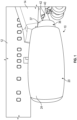
- Aircraft 10 includes a fuselage 12 that supports a wing 14.
- An engine system 20 including a nacelle 24 is supported by wing 14.
- Nacelle 24 surrounds and protects engine system 20.
- engine system 20 may also be directly supported by fuselage 12 or be mounted to tail surfaces (not shown) of aircraft 10.
- engine system 20 includes a turbine engine 28 supported within nacelle 24.
- Turbine engine 28 includes a high pressure spool 30 connected to a low pressure spool 32.
- a low pressure spool shaft 34 extends from low pressure spool 32.
- An engine duct 36 including an outer surface section 37 and an inner surface section 38 extends about turbine engine 28 and provides a pathway for air flow.
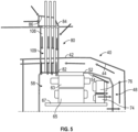
- turbine engine 28 includes a tail cone 40 having an outer surface 42 and an inner surface 44.
- a generator housing 48 is arranged within tail cone 40. Referring to FIG. 3 , generator housing 48 takes the form of a service frame (not separately labeled) having a first outer surface portion 52 and a first inner surface portion 54. A second outer surface portion 55 is spaced from first inner surface portion 54. A second inner surface portion 56 extends about a generator 58
- generator 58 includes a stator 63 including a stator winding (not separately labeled) supported by second inner surface portion 56.
- a rotor 65 including a rotor winding (also not separately labeled) is supported on a shaft 67 within stator 63.
- Shaft 67 is supported in generator housing 48 through a first bearing 69 and a second bearing 71.
- Generator 58 is also shown to include a secondary stator 74 axially spaced from stator 63.
- a second rotor 76 is supported on shaft 67 axially spaced from rotor 65 and is rotatable within secondary stator 74.
- a first air duct 80 extends from within generator housing 48.
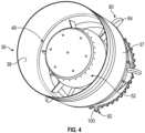
- First air duct 80 includes a first end 82 positioned inwardly of second inner surface portion 56 and a second end 84 ( FIG. 2 ) that is positioned outwardly of engine duct 36 as shown in FIG. 2 .
- First air duct 80 extends through generator housing, tail cone 40 and engine duct 36 with second end 84 being exposed to an air stream passing over turbine engine 28. That is, second end 84 of first air duct 80 includes an opening 86 that faces a first direction and defines an inlet (not separately labeled) that receives air flowing over turbine engine 28.
- the air passes through first air duct 80 and into generator housing 48.
- the air passes between rotor 65 and stator 63 as well as over stator 63.
- the air also passes between secondary stator 74 and second rotor 76.
- portions of first air duct 80 that extend between tail cone 40 and engine duct 36 may include an aerodynamic profile as shown in FIG. 4 .
- a second air duct 92 may extend from within generator housing 48.
- Second air duct 92 includes a first end section 96 that may be positioned between first outer surface portion 52 of generator housing 48 and inner surface 44 of tail cone 40 and a second end section 98 that is arranged outwardly of engine duct 36.
- Second end section 98 includes an opening 100 ( FIG. 2 ) that faces a second direction opposite to that of opening 86 and defines an outlet. In this manner, air that has exchanged heat with internal components of generator 58 may be expelled into tail cone 40, through second air duct 92, and into an airstream passing over turbine engine 28.
- the number, orientation, and circumferential location of air ducts may vary.
- first air duct 80 is shown to also act as a conduit 108 that carries electrical conductors 109 from a first terminal block (not shown) positioned on generator housing 48 to a second terminal block (also not shown) that may be arranged in nacelle 24 and or wing 14.
- FIG. 6 depicts a generator housing 48 in which air passes not only between stator 63/rotor 65 and secondary stator 74/second rotor 79 but also through rotor 65 and second rotor 76 in order to further improve cooling.
Landscapes
- Engineering & Computer Science (AREA)
- Mechanical Engineering (AREA)
- General Engineering & Computer Science (AREA)
- Chemical & Material Sciences (AREA)
- Combustion & Propulsion (AREA)
- Power Engineering (AREA)
- Aviation & Aerospace Engineering (AREA)
- Connection Of Motors, Electrical Generators, Mechanical Devices, And The Like (AREA)
Claims (9)
- Système de moteur, comprenant :une bobine haute pression ;un tiroir basse pression relié à la bobine haute pression ;un conduit de moteur (36) se prolongeant autour du tiroir haute pression et du tiroir basse pression, le conduit de moteur incluant une section de surface extérieure exposée à un flux d'air externe ;un cône de queue (40) disposé radialement vers l'intérieur du conduit de moteur, le cône de queue présentant une surface extérieure (42) et une surface intérieure (44) ;un boîtier de générateur (48) disposé dans le cône de queue, le boîtier de générateur incluant une partie de surface extérieure (52) espacée de la surface intérieure du cône de queue ;un générateur (58) monté dans le boîtier de générateur et entraîné par la bobine basse pression ; etun conduit d'air (80) se prolongeant depuis le générateur, à travers le boîtier de générateur, à travers le cône de queue et à travers le conduit de moteur, le conduit d'air incluant une première extrémité (82) disposée dans le cône de queue et une seconde extrémité (84) faisant saillie vers l'extérieur de la section de surface extérieure du conduit de moteur à l'arrière de la bobine basse pression, la seconde extrémité incluant une ouverture (86) exposée au flux d'air externe passant sur le conduit de moteur.
- Système de moteur selon la revendication 1, comprenant également : un autre conduit d'air (92) se prolongeant depuis le générateur (58), à travers le boîtier de générateur (48), à travers le cône de queue (40) et à travers le conduit de moteur, l'autre conduit d'air (92) incluant une autre ouverture exposée à un flux d'air passant sur le conduit de moteur (36) ; et éventuellement dans lequel : le conduit d'air comprend un conduit d'entrée pour diriger un flux d'air dans le boîtier de générateur et l'autre conduit d'air comprend un conduit d'air de sortie pour diriger le flux d'air hors du boîtier de générateur.
- Système de moteur selon la revendication 1 ou 2, comprenant également : un plénum défini entre la partie de surface extérieure (52) du boîtier de générateur (48) et la surface intérieure (44) du cône de queue (40) et éventuellement dans lequel le conduit de sortie est relié fluidiquement au plénum.
- Système de moteur selon la revendication 3, dans lequel le générateur (58) inclut un arbre d'entraînement pouvant être relié à la bobine basse pression (32) du système de moteur, l'arbre d'entraînement présentant un intérieur creux relié fluidiquement au plénum par un passage de sortie.
- Système de moteur selon l'une quelconque des revendications 2 à 4, dans lequel l'ouverture (86) du conduit d'air (80) fait face à une première direction par rapport au conduit de moteur et l'autre ouverture de l'autre conduit d'air fait face à une seconde direction qui est distincte de la première direction ; et éventuellement dans lequel la première direction est directement opposée à la seconde direction.
- Système de moteur selon une quelconque revendication précédente, comprenant également : une pluralité de conducteurs électriques connectés au générateur (58), la pluralité de conducteurs électriques passant du générateur à travers le conduit d'air (80).
- Aéronef, comprenant :un fuselage (12) ;une aile (14) supportée par le fuselage ;un système de moteur (20) selon une quelconque revendication précédente supporté par le fuselage, le système de moteur incluant une nacelle (24) entourant un moteur.
- Aéronef selon la revendication 7, dans lequel le système de moteur (20) est supporté dans la nacelle (24), la nacelle étant montée sur le fuselage (12).
- Aéronef selon la revendication 7 ou 8, dans lequel l'aile (14) est montée de manière fixe sur le fuselage (12).
Applications Claiming Priority (1)
| Application Number | Priority Date | Filing Date | Title |
|---|---|---|---|
| US17/529,625 US11821370B2 (en) | 2021-11-18 | 2021-11-18 | Cooling system for tail cone mounted generator |
Publications (2)
| Publication Number | Publication Date |
|---|---|
| EP4183996A1 EP4183996A1 (fr) | 2023-05-24 |
| EP4183996B1 true EP4183996B1 (fr) | 2025-02-12 |
Family
ID=84331986
Family Applications (1)
| Application Number | Title | Priority Date | Filing Date |
|---|---|---|---|
| EP22200961.5A Active EP4183996B1 (fr) | 2021-11-18 | 2022-10-11 | Système de refroidissement pour générateur monté sur cône de queue |
Country Status (2)
| Country | Link |
|---|---|
| US (1) | US11821370B2 (fr) |
| EP (1) | EP4183996B1 (fr) |
Families Citing this family (2)
| Publication number | Priority date | Publication date | Assignee | Title |
|---|---|---|---|---|
| US12264623B1 (en) * | 2024-01-18 | 2025-04-01 | Honeywell International Inc. | System for electric machine associated with gas turbine engine |
| US12372010B1 (en) | 2024-01-26 | 2025-07-29 | Rtx Corporation | Passive ventilation system for tail cone zone |
Family Cites Families (9)
| Publication number | Priority date | Publication date | Assignee | Title |
|---|---|---|---|---|
| US8729751B2 (en) * | 2010-11-10 | 2014-05-20 | Hamilton Sundstrand Corporation | Heat transfer assembly for electric motor rotor |
| US9003811B2 (en) | 2011-11-28 | 2015-04-14 | Pratt & Whitney Canada Corp. | Support for electric machine in a turbine engine |
| US9194330B2 (en) * | 2012-07-31 | 2015-11-24 | United Technologies Corporation | Retrofitable auxiliary inlet scoop |
| US9097134B2 (en) | 2012-09-14 | 2015-08-04 | Pratt & Whitney Canada Corp. | Air cooling design for tail-cone generator installation |
| US10208676B2 (en) * | 2016-03-29 | 2019-02-19 | General Electric Company | Gas turbine engine dual sealing cylindrical variable bleed valve |
| US10801410B2 (en) * | 2018-04-12 | 2020-10-13 | Raytheon Technologies Corporation | Thermal management of tail cone mounted generator |
| JP7143904B2 (ja) * | 2019-02-13 | 2022-09-29 | 株式会社Ihi | 航空機用ガスタービンエンジンの冷却システム |
| WO2021014667A1 (fr) * | 2019-07-24 | 2021-01-28 | 株式会社Ihi | Système de refroidissement de générateur de moteur de turbo-ventilateur |
| US11637475B2 (en) | 2020-03-09 | 2023-04-25 | Hamilton Sundstrand Corporation | Terminal block for integrated tail cone and mounted generator |
-
2021
- 2021-11-18 US US17/529,625 patent/US11821370B2/en active Active
-
2022
- 2022-10-11 EP EP22200961.5A patent/EP4183996B1/fr active Active
Also Published As
| Publication number | Publication date |
|---|---|
| US20230151771A1 (en) | 2023-05-18 |
| US11821370B2 (en) | 2023-11-21 |
| EP4183996A1 (fr) | 2023-05-24 |
Similar Documents
| Publication | Publication Date | Title |
|---|---|---|
| CN108725804B (zh) | 用于飞行器的推进系统 | |
| EP2409919B1 (fr) | Refroidissement de moteur de ventilateur d'air dynamique | |
| CN108368852B (zh) | 涡轮发动机或航空器的电动离心式压缩机 | |
| US9287747B2 (en) | Wind power generator with internal cooling circuit | |
| EP3176408A1 (fr) | Système et procédé de refroidissement intermédiaire pour un moteur à turbine à gaz | |
| US10823067B2 (en) | System for a surface cooler with OGV oriented fin angles | |
| EP3764523B1 (fr) | Machine électrique avec système de refroidissement intégré | |
| JP2017125499A (ja) | 停止後エンジン温度低減システム及び方法 | |
| EP4019784B1 (fr) | Compresseur d'air de cabine avec passage refroidi par liquide formé dans le boîtier | |
| EP4183996B1 (fr) | Système de refroidissement pour générateur monté sur cône de queue | |
| EP3628598B1 (fr) | Refroidissement de convertisseur de puissance | |
| EP4019785B1 (fr) | Compresseur d'air de cabine avec gaine refroidie par liquide | |
| CN114909222B (zh) | 包括嵌入式电机和相关联冷却系统的燃气涡轮发动机 | |
| EP3176409A1 (fr) | Procédé de refroidissement en circuit fermé pour une turbomachine | |
| CN114915101B (zh) | 用于集成到推进发动机中的电机 | |
| US11255215B2 (en) | Gas turbine engine with microchannel cooled electric device | |
| EP3633162B1 (fr) | Système d'échangeur de chaleur de turboréacteur | |
| EP4287464A1 (fr) | Ensemble rotor pour une machine électrique | |
| EP3550149B1 (fr) | Virole d'entrée de soufflante d'air dynamique à structure améliorée | |
| CN120638698A (zh) | 具有冷却特征的电机 | |
| CN120601656A (zh) | 用于电机的定子 | |
| US20260005582A1 (en) | Cooling assembly for electric machine | |
| US20110221288A1 (en) | System and method for cooling in electric machines | |
| CN121932286A (zh) | 电力传输系统 | |
| CN118442184A (zh) | 包括传动齿轮箱和附件齿轮箱的涡轮发动机 |
Legal Events
| Date | Code | Title | Description |
|---|---|---|---|
| PUAI | Public reference made under article 153(3) epc to a published international application that has entered the european phase |
Free format text: ORIGINAL CODE: 0009012 |
|
| STAA | Information on the status of an ep patent application or granted ep patent |
Free format text: STATUS: THE APPLICATION HAS BEEN PUBLISHED |
|
| AK | Designated contracting states |
Kind code of ref document: A1 Designated state(s): AL AT BE BG CH CY CZ DE DK EE ES FI FR GB GR HR HU IE IS IT LI LT LU LV MC ME MK MT NL NO PL PT RO RS SE SI SK SM TR |
|
| STAA | Information on the status of an ep patent application or granted ep patent |
Free format text: STATUS: REQUEST FOR EXAMINATION WAS MADE |
|
| 17P | Request for examination filed |
Effective date: 20231121 |
|
| RBV | Designated contracting states (corrected) |
Designated state(s): AL AT BE BG CH CY CZ DE DK EE ES FI FR GB GR HR HU IE IS IT LI LT LU LV MC ME MK MT NL NO PL PT RO RS SE SI SK SM TR |
|
| GRAP | Despatch of communication of intention to grant a patent |
Free format text: ORIGINAL CODE: EPIDOSNIGR1 |
|
| STAA | Information on the status of an ep patent application or granted ep patent |
Free format text: STATUS: GRANT OF PATENT IS INTENDED |
|
| INTG | Intention to grant announced |
Effective date: 20240911 |
|
| GRAS | Grant fee paid |
Free format text: ORIGINAL CODE: EPIDOSNIGR3 |
|
| GRAA | (expected) grant |
Free format text: ORIGINAL CODE: 0009210 |
|
| STAA | Information on the status of an ep patent application or granted ep patent |
Free format text: STATUS: THE PATENT HAS BEEN GRANTED |
|
| AK | Designated contracting states |
Kind code of ref document: B1 Designated state(s): AL AT BE BG CH CY CZ DE DK EE ES FI FR GB GR HR HU IE IS IT LI LT LU LV MC ME MK MT NL NO PL PT RO RS SE SI SK SM TR |
|
| REG | Reference to a national code |
Ref country code: GB Ref legal event code: FG4D |
|
| REG | Reference to a national code |
Ref country code: CH Ref legal event code: EP |
|
| REG | Reference to a national code |
Ref country code: DE Ref legal event code: R096 Ref document number: 602022010438 Country of ref document: DE |
|
| REG | Reference to a national code |
Ref country code: IE Ref legal event code: FG4D |
|
| REG | Reference to a national code |
Ref country code: NL Ref legal event code: MP Effective date: 20250212 |
|
| PG25 | Lapsed in a contracting state [announced via postgrant information from national office to epo] |
Ref country code: RS Free format text: LAPSE BECAUSE OF FAILURE TO SUBMIT A TRANSLATION OF THE DESCRIPTION OR TO PAY THE FEE WITHIN THE PRESCRIBED TIME-LIMIT Effective date: 20250512 |
|
| PG25 | Lapsed in a contracting state [announced via postgrant information from national office to epo] |
Ref country code: FI Free format text: LAPSE BECAUSE OF FAILURE TO SUBMIT A TRANSLATION OF THE DESCRIPTION OR TO PAY THE FEE WITHIN THE PRESCRIBED TIME-LIMIT Effective date: 20250212 |
|
| PG25 | Lapsed in a contracting state [announced via postgrant information from national office to epo] |
Ref country code: PL Free format text: LAPSE BECAUSE OF FAILURE TO SUBMIT A TRANSLATION OF THE DESCRIPTION OR TO PAY THE FEE WITHIN THE PRESCRIBED TIME-LIMIT Effective date: 20250212 |
|
| PG25 | Lapsed in a contracting state [announced via postgrant information from national office to epo] |
Ref country code: ES Free format text: LAPSE BECAUSE OF FAILURE TO SUBMIT A TRANSLATION OF THE DESCRIPTION OR TO PAY THE FEE WITHIN THE PRESCRIBED TIME-LIMIT Effective date: 20250212 |
|
| REG | Reference to a national code |
Ref country code: LT Ref legal event code: MG9D |
|
| PG25 | Lapsed in a contracting state [announced via postgrant information from national office to epo] |
Ref country code: IS Free format text: LAPSE BECAUSE OF FAILURE TO SUBMIT A TRANSLATION OF THE DESCRIPTION OR TO PAY THE FEE WITHIN THE PRESCRIBED TIME-LIMIT Effective date: 20250612 Ref country code: NO Free format text: LAPSE BECAUSE OF FAILURE TO SUBMIT A TRANSLATION OF THE DESCRIPTION OR TO PAY THE FEE WITHIN THE PRESCRIBED TIME-LIMIT Effective date: 20250512 |
|
| PG25 | Lapsed in a contracting state [announced via postgrant information from national office to epo] |
Ref country code: NL Free format text: LAPSE BECAUSE OF FAILURE TO SUBMIT A TRANSLATION OF THE DESCRIPTION OR TO PAY THE FEE WITHIN THE PRESCRIBED TIME-LIMIT Effective date: 20250212 |
|
| PG25 | Lapsed in a contracting state [announced via postgrant information from national office to epo] |
Ref country code: HR Free format text: LAPSE BECAUSE OF FAILURE TO SUBMIT A TRANSLATION OF THE DESCRIPTION OR TO PAY THE FEE WITHIN THE PRESCRIBED TIME-LIMIT Effective date: 20250212 |
|
| PG25 | Lapsed in a contracting state [announced via postgrant information from national office to epo] |
Ref country code: PT Free format text: LAPSE BECAUSE OF FAILURE TO SUBMIT A TRANSLATION OF THE DESCRIPTION OR TO PAY THE FEE WITHIN THE PRESCRIBED TIME-LIMIT Effective date: 20250612 Ref country code: LV Free format text: LAPSE BECAUSE OF FAILURE TO SUBMIT A TRANSLATION OF THE DESCRIPTION OR TO PAY THE FEE WITHIN THE PRESCRIBED TIME-LIMIT Effective date: 20250212 |
|
| PG25 | Lapsed in a contracting state [announced via postgrant information from national office to epo] |
Ref country code: BG Free format text: LAPSE BECAUSE OF FAILURE TO SUBMIT A TRANSLATION OF THE DESCRIPTION OR TO PAY THE FEE WITHIN THE PRESCRIBED TIME-LIMIT Effective date: 20250212 Ref country code: GR Free format text: LAPSE BECAUSE OF FAILURE TO SUBMIT A TRANSLATION OF THE DESCRIPTION OR TO PAY THE FEE WITHIN THE PRESCRIBED TIME-LIMIT Effective date: 20250513 |
|
| REG | Reference to a national code |
Ref country code: AT Ref legal event code: MK05 Ref document number: 1766232 Country of ref document: AT Kind code of ref document: T Effective date: 20250212 |
|
| PG25 | Lapsed in a contracting state [announced via postgrant information from national office to epo] |
Ref country code: SE Free format text: LAPSE BECAUSE OF FAILURE TO SUBMIT A TRANSLATION OF THE DESCRIPTION OR TO PAY THE FEE WITHIN THE PRESCRIBED TIME-LIMIT Effective date: 20250212 |
|
| PG25 | Lapsed in a contracting state [announced via postgrant information from national office to epo] |
Ref country code: SM Free format text: LAPSE BECAUSE OF FAILURE TO SUBMIT A TRANSLATION OF THE DESCRIPTION OR TO PAY THE FEE WITHIN THE PRESCRIBED TIME-LIMIT Effective date: 20250212 |
|
| PG25 | Lapsed in a contracting state [announced via postgrant information from national office to epo] |
Ref country code: DK Free format text: LAPSE BECAUSE OF FAILURE TO SUBMIT A TRANSLATION OF THE DESCRIPTION OR TO PAY THE FEE WITHIN THE PRESCRIBED TIME-LIMIT Effective date: 20250212 |
|
| PG25 | Lapsed in a contracting state [announced via postgrant information from national office to epo] |
Ref country code: IT Free format text: LAPSE BECAUSE OF FAILURE TO SUBMIT A TRANSLATION OF THE DESCRIPTION OR TO PAY THE FEE WITHIN THE PRESCRIBED TIME-LIMIT Effective date: 20250212 |
|
| PG25 | Lapsed in a contracting state [announced via postgrant information from national office to epo] |
Ref country code: AT Free format text: LAPSE BECAUSE OF FAILURE TO SUBMIT A TRANSLATION OF THE DESCRIPTION OR TO PAY THE FEE WITHIN THE PRESCRIBED TIME-LIMIT Effective date: 20250212 |
|
| PGFP | Annual fee paid to national office [announced via postgrant information from national office to epo] |
Ref country code: FR Payment date: 20250923 Year of fee payment: 4 |
|
| PG25 | Lapsed in a contracting state [announced via postgrant information from national office to epo] |
Ref country code: EE Free format text: LAPSE BECAUSE OF FAILURE TO SUBMIT A TRANSLATION OF THE DESCRIPTION OR TO PAY THE FEE WITHIN THE PRESCRIBED TIME-LIMIT Effective date: 20250212 Ref country code: CZ Free format text: LAPSE BECAUSE OF FAILURE TO SUBMIT A TRANSLATION OF THE DESCRIPTION OR TO PAY THE FEE WITHIN THE PRESCRIBED TIME-LIMIT Effective date: 20250212 |
|
| PG25 | Lapsed in a contracting state [announced via postgrant information from national office to epo] |
Ref country code: RO Free format text: LAPSE BECAUSE OF FAILURE TO SUBMIT A TRANSLATION OF THE DESCRIPTION OR TO PAY THE FEE WITHIN THE PRESCRIBED TIME-LIMIT Effective date: 20250212 |
|
| PG25 | Lapsed in a contracting state [announced via postgrant information from national office to epo] |
Ref country code: SK Free format text: LAPSE BECAUSE OF FAILURE TO SUBMIT A TRANSLATION OF THE DESCRIPTION OR TO PAY THE FEE WITHIN THE PRESCRIBED TIME-LIMIT Effective date: 20250212 |
|
| REG | Reference to a national code |
Ref country code: DE Ref legal event code: R097 Ref document number: 602022010438 Country of ref document: DE |
|
| PLBE | No opposition filed within time limit |
Free format text: ORIGINAL CODE: 0009261 |
|
| STAA | Information on the status of an ep patent application or granted ep patent |
Free format text: STATUS: NO OPPOSITION FILED WITHIN TIME LIMIT |
|
| 26N | No opposition filed |
Effective date: 20251113 |