EP4184023B1 - Mécanisme de rotation et terminal pliable - Google Patents
Mécanisme de rotation et terminal pliable Download PDFInfo
- Publication number
- EP4184023B1 EP4184023B1 EP22826584.9A EP22826584A EP4184023B1 EP 4184023 B1 EP4184023 B1 EP 4184023B1 EP 22826584 A EP22826584 A EP 22826584A EP 4184023 B1 EP4184023 B1 EP 4184023B1
- Authority
- EP
- European Patent Office
- Prior art keywords
- rotation shaft
- support plate
- shaft part
- rotation
- fixed base
- Prior art date
- Legal status (The legal status is an assumption and is not a legal conclusion. Google has not performed a legal analysis and makes no representation as to the accuracy of the status listed.)
- Active
Links
Images






Classifications
-
- H—ELECTRICITY
- H04—ELECTRIC COMMUNICATION TECHNIQUE
- H04M—TELEPHONIC COMMUNICATION
- H04M1/00—Substation equipment, e.g. for use by subscribers
- H04M1/02—Constructional features of telephone sets
- H04M1/0202—Portable telephone sets, e.g. cordless phones, mobile phones or bar type handsets
- H04M1/0206—Portable telephones comprising a plurality of mechanically joined movable body parts, e.g. hinged housings
- H04M1/0208—Portable telephones comprising a plurality of mechanically joined movable body parts, e.g. hinged housings characterized by the relative motions of the body parts
- H04M1/0214—Foldable telephones, i.e. with body parts pivoting to an open position around an axis parallel to the plane they define in closed position
- H04M1/0216—Foldable in one direction, i.e. using a one degree of freedom hinge
-
- H—ELECTRICITY
- H04—ELECTRIC COMMUNICATION TECHNIQUE
- H04M—TELEPHONIC COMMUNICATION
- H04M1/00—Substation equipment, e.g. for use by subscribers
- H04M1/02—Constructional features of telephone sets
- H04M1/0202—Portable telephone sets, e.g. cordless phones, mobile phones or bar type handsets
- H04M1/0206—Portable telephones comprising a plurality of mechanically joined movable body parts, e.g. hinged housings
- H04M1/0208—Portable telephones comprising a plurality of mechanically joined movable body parts, e.g. hinged housings characterized by the relative motions of the body parts
- H04M1/0214—Foldable telephones, i.e. with body parts pivoting to an open position around an axis parallel to the plane they define in closed position
- H04M1/0216—Foldable in one direction, i.e. using a one degree of freedom hinge
- H04M1/022—The hinge comprising two parallel pivoting axes
-
- G—PHYSICS
- G06—COMPUTING OR CALCULATING; COUNTING
- G06F—ELECTRIC DIGITAL DATA PROCESSING
- G06F1/00—Details not covered by groups G06F3/00 - G06F13/00 and G06F21/00
- G06F1/16—Constructional details or arrangements
- G06F1/1613—Constructional details or arrangements for portable computers
- G06F1/1633—Constructional details or arrangements of portable computers not specific to the type of enclosures covered by groups G06F1/1615 - G06F1/1626
- G06F1/1637—Details related to the display arrangement, including those related to the mounting of the display in the housing
- G06F1/1652—Details related to the display arrangement, including those related to the mounting of the display in the housing the display being flexible, e.g. mimicking a sheet of paper, or rollable
-
- G—PHYSICS
- G06—COMPUTING OR CALCULATING; COUNTING
- G06F—ELECTRIC DIGITAL DATA PROCESSING
- G06F1/00—Details not covered by groups G06F3/00 - G06F13/00 and G06F21/00
- G06F1/16—Constructional details or arrangements
- G06F1/1613—Constructional details or arrangements for portable computers
- G06F1/1633—Constructional details or arrangements of portable computers not specific to the type of enclosures covered by groups G06F1/1615 - G06F1/1626
- G06F1/1675—Miscellaneous details related to the relative movement between the different enclosures or enclosure parts
- G06F1/1681—Details related solely to hinges
-
- H—ELECTRICITY
- H04—ELECTRIC COMMUNICATION TECHNIQUE
- H04M—TELEPHONIC COMMUNICATION
- H04M1/00—Substation equipment, e.g. for use by subscribers
- H04M1/02—Constructional features of telephone sets
- H04M1/0202—Portable telephone sets, e.g. cordless phones, mobile phones or bar type handsets
- H04M1/0206—Portable telephones comprising a plurality of mechanically joined movable body parts, e.g. hinged housings
- H04M1/0208—Portable telephones comprising a plurality of mechanically joined movable body parts, e.g. hinged housings characterized by the relative motions of the body parts
- H04M1/0235—Slidable or telescopic telephones, i.e. with a relative translation movement of the body parts; Telephones using a combination of translation and other relative motions of the body parts
-
- H—ELECTRICITY
- H04—ELECTRIC COMMUNICATION TECHNIQUE
- H04M—TELEPHONIC COMMUNICATION
- H04M1/00—Substation equipment, e.g. for use by subscribers
- H04M1/02—Constructional features of telephone sets
- H04M1/0202—Portable telephone sets, e.g. cordless phones, mobile phones or bar type handsets
- H04M1/026—Details of the structure or mounting of specific components
- H04M1/0266—Details of the structure or mounting of specific components for a display module assembly
- H04M1/0268—Details of the structure or mounting of specific components for a display module assembly including a flexible display panel
-
- E—FIXED CONSTRUCTIONS
- E05—LOCKS; KEYS; WINDOW OR DOOR FITTINGS; SAFES
- E05D—HINGES OR SUSPENSION DEVICES FOR DOORS, WINDOWS OR WINGS
- E05D1/00—Pinless hinges; Substitutes for hinges
- E05D1/04—Pinless hinges; Substitutes for hinges with guide members shaped as circular arcs
-
- E—FIXED CONSTRUCTIONS
- E05—LOCKS; KEYS; WINDOW OR DOOR FITTINGS; SAFES
- E05Y—INDEXING SCHEME ASSOCIATED WITH SUBCLASSES E05D AND E05F, RELATING TO CONSTRUCTION ELEMENTS, ELECTRIC CONTROL, POWER SUPPLY, POWER SIGNAL OR TRANSMISSION, USER INTERFACES, MOUNTING OR COUPLING, DETAILS, ACCESSORIES, AUXILIARY OPERATIONS NOT OTHERWISE PROVIDED FOR, APPLICATION THEREOF
- E05Y2999/00—Subject-matter not otherwise provided for in this subclass
-
- Y—GENERAL TAGGING OF NEW TECHNOLOGICAL DEVELOPMENTS; GENERAL TAGGING OF CROSS-SECTIONAL TECHNOLOGIES SPANNING OVER SEVERAL SECTIONS OF THE IPC; TECHNICAL SUBJECTS COVERED BY FORMER USPC CROSS-REFERENCE ART COLLECTIONS [XRACs] AND DIGESTS
- Y02—TECHNOLOGIES OR APPLICATIONS FOR MITIGATION OR ADAPTATION AGAINST CLIMATE CHANGE
- Y02E—REDUCTION OF GREENHOUSE GAS [GHG] EMISSIONS, RELATED TO ENERGY GENERATION, TRANSMISSION OR DISTRIBUTION
- Y02E60/00—Enabling technologies; Technologies with a potential or indirect contribution to GHG emissions mitigation
- Y02E60/10—Energy storage using batteries
-
- Y—GENERAL TAGGING OF NEW TECHNOLOGICAL DEVELOPMENTS; GENERAL TAGGING OF CROSS-SECTIONAL TECHNOLOGIES SPANNING OVER SEVERAL SECTIONS OF THE IPC; TECHNICAL SUBJECTS COVERED BY FORMER USPC CROSS-REFERENCE ART COLLECTIONS [XRACs] AND DIGESTS
- Y02—TECHNOLOGIES OR APPLICATIONS FOR MITIGATION OR ADAPTATION AGAINST CLIMATE CHANGE
- Y02P—CLIMATE CHANGE MITIGATION TECHNOLOGIES IN THE PRODUCTION OR PROCESSING OF GOODS
- Y02P70/00—Climate change mitigation technologies in the production process for final industrial or consumer products
- Y02P70/50—Manufacturing or production processes characterised by the final manufactured product
Definitions
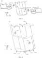
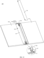
- This application relates to the field of foldable terminals, and in particular, to a rotation mechanism and a foldable terminal.
- a foldable terminal With the development of science and technology, the era of a large-screen intelligent terminal is approaching, and a foldable terminal is favored by a user because of advantages such as a large screen and easy-to-carry.
- a foldable terminal usually implements folding and unfolding by using a rotation mechanism.
- a thickness of an existing rotation mechanism is often relatively large, which is not conducive to implementing a light and thin design of the foldable terminal.
- this application provides a rotation mechanism, including a fixed base, a first swing arm, a second swing arm, a first limiting member, and a second limiting member.
- a first sliding groove and a second sliding groove are disposed on the fixed base. Both openings of the first sliding groove and the second sliding groove are located on a top surface of the fixed base. Both the first sliding groove and the second sliding groove are recessed from a top-bottom direction of the fixed base. For example, both the first sliding groove and the second sliding groove are circular arc grooves.
- the first swing arm includes a first rotation shaft part, and the first rotation shaft part is installed in the first sliding groove, and may rotate relative to the fixed base.
- the first rotation shaft part is located at one end of the first swing arm.
- the first rotation shaft part is an arc-shaped plate, and is adapted to the first sliding groove.
- the first rotation shaft part projects in a direction facing away from the top surface of the first swing part.
- the first rotation shaft part is provided with a first sliding hole, and the first sliding hole runs through the first rotation shaft part in a thickness direction of the first rotation shaft part.
- the first sliding hole is a circular arc hole.
- the second swing arm includes a second rotation shaft part, and the second rotation shaft part is installed in the second sliding groove, and may rotate relative to the fixed base.
- the second rotation shaft part is located at one end of the second swing arm.
- the second rotation shaft part is an arc-shaped plate, and is adapted to the second sliding groove.
- the second rotation shaft part projects in a direction facing away from the top surface of the second swing part.
- the second rotation shaft part is provided with a second sliding hole, and the second sliding hole runs through the second rotation shaft part in a thickness direction of the second rotation shaft part.
- the second sliding hole is a circular arc hole.
- first rotation shaft part rotates in a counterclockwise direction relative to the fixed base
- second rotation shaft part rotates in a clockwise direction relative to the fixed base.
- first swing arm and the second swing arm rotate relative to the fixed base to fold relatively.
- first rotation shaft part rotates in a clockwise direction relative to the fixed base
- the second rotation shaft part rotates in a counterclockwise direction relative to the fixed base.
- first swing arm and the second swing arm rotate relative to the fixed base to unfold relatively.
- the first rotation shaft part rotates relative to the fixed base, the first rotation shaft part slides relative to the first limiting member along the first sliding hole, so that the first limiting member slides relative to the first rotation shaft part along the first sliding hole.
- the second limiting member is disposed in the second sliding hole, and is fixedly connected to the fixed base. When the second rotation shaft part rotates relative to the fixed base, the second limiting member slides relative to the second rotation shaft part along the second sliding hole.
- the second rotation shaft part rotates relative to the fixed base, the second rotation shaft part slides along the second sliding hole relative to the second limiting member, so as to implement sliding of the second limiting member along the second sliding hole relative to the second rotation shaft part.
- a width direction of the rotation mechanism is an X-axis direction
- a length direction of the rotation mechanism is a Y-axis direction
- a thickness direction of the rotation mechanism is a Z-axis direction
- the X-axis direction, the Y-axis direction, and the Z-axis direction are perpendicular to each other.
- rotation of the rotation mechanism can be implemented only by using the fixed base, the first swing arm, and the second swing arm.
- a structure of the rotation mechanism shown in this application is simple, which helps reduce costs of the rotation mechanism.
- the first swing arm and the second swing arm respectively slide with the first sliding groove and the second sliding groove of the fixed base, that is, a single-layer sliding groove may be used to implement rotation of the rotation mechanism, which is conducive to reducing a thickness of the fixed base, the first swing arm, and the second swing arm.
- the rotation mechanism shown in this application may reduce at least one layer of a thickness (about 0.6 mm) of a structural member, which is conducive to implementing a light and thin design of the rotation mechanism.
- a rotation track of each of the first swing arm and the second swing arm relative to the fixed base may be limited by cooperation between the first limiting member and the second limiting member and the fixed base, so as to prevent misalignment between the first swing arm and the second swing arm and the fixed base in the Y-axis direction and the Z-axis direction, thereby improving rotation stability of the rotation mechanism.
- the fixed base is provided with a first fixing hole and a second fixing hole, an opening of the first fixing hole is located on a groove bottom wall of the first sliding groove, and an opening of the second fixing hole is located on a groove bottom wall of the second sliding groove.
- the first sliding part slides relative to the first rotation shaft part in the first sliding hole, so as to limit the first rotation shaft part in the Y-axis direction, so that no misalignment occurs between the first swing arm and the fixed base in the Y-axis direction, thereby limiting a rotation track of the first rotation shaft part relative to the fixed base.
- the second limiting member includes a second fixing part, a second sliding part, and a second limiting member that are connected in sequence, where the second fixing part is in the second fixing hole, and is fixed to a hole wall of the second fixing hole, so as to implement fastening connection between the second limiting member and the fixed base.
- the second sliding part is located in the second sliding hole.
- a top surface of the second limiting member is exposed relative to the second rotation shaft part.
- a bottom surface of the second limiting member is clamped on a top surface of the second rotation shaft part, so as to limit the second rotation shaft part in a Z-axis direction, so that no misalignment occurs between the second swing arm and the fixed base in a Z-axis direction, which helps improve assembly stability between the second swing arm and the fixed base.
- the second sliding part slides relative to the second rotation shaft part in the second sliding hole, so as to limit the second rotation shaft part in the Y-axis direction, so that no misalignment occurs between the second swing arm and the fixed base in the Y-axis direction, thereby limiting a rotation track of the second rotation shaft part relative to the fixed base.
- the rotation mechanism further includes a drive member, and the drive member is connected between the first swing arm and the second swing arm, so that when the first swing arm rotates relative to the fixed base, the second swing arm rotates relative to the fixed base, or when the second swing arm rotates relative to the fixed base, the first swing arm rotates relative to the fixed base, so as to implement synchronous rotation between the first swing arm and the second swing arm relative to the fixed base.
- the drive member may be a gear or another part that can implement rotation.
- a top surface of the first limiting member is located between the top surface of the first swing part and the top surface of the first rotation shaft part. That is, the top surface of the first limiting member does not protrude relative to the top surface of the first swing part, so that the first limiting member reuses space in the Z-axis direction with the first rotation shaft part and the fixed base, so as to reduce the size of the rotation mechanism in the Z-axis direction, which helps to implement a light and thin design of the rotation mechanism.
- the top surface of the first support plate and the top surface of the second support plate form a support surface, which is used to support a foldable part of a display screen, so as to ensure good display of the display screen.
- the first support plate is provided with a first avoidance hole, and the first avoidance hole runs through the first support plate in a thickness direction of the first support plate and is configured to avoid the first limiting member, so as to avoid interference between the first support plate and the first limiting member when the first support plate rotates relative to the fixed base, thereby ensuring rotation fluency of the rotation mechanism.
- the first rotation shaft part and the second rotation shaft part are arranged in the X-axis direction at intervals.
- the first rotation shaft part and the second rotation shaft part are arranged in an overlapping manner in the Y-axis direction.
- the first rotation shaft part and the second rotation shaft part are partially arranged or fully arranged in an overlapping manner, so that the size of the rotation mechanism in the Y-axis direction can be reduced, and a miniaturization design of the rotation mechanism can be implemented.
- the first support plate is provided with a first protrusion and a first notch.
- the first protrusion is connected to a surface of the first support plate facing the second support plate.
- the first protrusion extends from the surface of the first support plate facing the second support plate towards a direction of the second support plate.
- a projection of the first protrusion on the first swing arm is located in the first rotation shaft part.
- An opening of the first notch is located on the surface of the first support plate facing the second support plate.
- the first notch is recessed from the surface of the first support plate facing the second support plate towards a direction facing away from the second support plate.
- a projection of the first notch on the second swing arm is located in the second rotation shaft part.
- the first protrusion When the rotation mechanism is in a flattened state, the first protrusion is engaged with the second notch, and the second protrusion is engaged with the first notch, so as to avoid interference between the first support plate and the second support plate and the fixed base when the first support plate and the second support plate rotate relative to the fixed base, thereby ensuring rotation fluency of the rotation mechanism.
- engagement between the protrusion and the notch means that the protrusion is located in the notch, and a circumferential surface of the protrusion abuts against a groove side wall of the notch.
- the rotation mechanism further includes a first auxiliary member and a second auxiliary member.
- the first auxiliary member is located on a side of the first rotation shaft part that faces away from a groove bottom wall of the first sliding groove. That is, the first rotation shaft part is located between the first auxiliary member and the groove bottom wall of the first sliding groove.
- the first auxiliary member is fixedly connected to the fixed base.
- the first auxiliary member is fixedly connected to a groove side wall of the first sliding groove.
- the first auxiliary member is provided with a first limiting hole connected to the first sliding groove.
- the first limiting member is further disposed in the first limiting hole.
- the first limiting member may be fixedly connected to the first auxiliary member.
- the first limiting member may be fixedly connected to a hole wall of the first limiting hole.
- the second auxiliary member is located on a side of the second rotation shaft part that faces away from the groove bottom wall of the second sliding groove. That is, the second rotation shaft part is located between the second auxiliary member and the groove bottom wall of the second sliding groove.
- the second auxiliary member is fixedly connected to the fixed base.
- the second auxiliary member is fixedly connected to the groove side wall of the second sliding groove.
- the second auxiliary member is provided with a second limiting hole connected to the second sliding groove, and the second limiting member is further disposed in the second mounting hole.
- the second limiting member may be fixedly connected to the second auxiliary member.
- the second limiting member may be fixedly connected to a hole wall of the second limiting hole.
- a contact area between the first limiting member and the second limiting member and the remaining parts of the rotation mechanism is increased, and a limiting effect of the first limiting member and the second limiting member is improved, thereby improving assembly stability between the parts of the rotation mechanism.
- a top surface of the second auxiliary member is located between the top surface of the second swing part and the top surface of the second rotation shaft part. That is, the top surface of the second auxiliary member does not protrude relative to the top surface of the second swing part, so that the second auxiliary member reuses space between the fixed base and the second swing arm in the Z-axis direction, which can reduce the size of the rotation mechanism in the Z-axis direction, which helps to implement a light and thin design of the rotation mechanism.
- the rotation mechanism has a symmetrical surface, and the two rotation components are symmetrical with respect to a symmetrical surface image.
- the rotation component has a central axis, and the rotation component is symmetrical with respect to the central axis.
- the first housing drives the first swing arm to rotate relative to the fixed base
- the second housing drives the second swing arm to rotate relative to the fixed base
- the foldable terminal shown in this application uses the foregoing rotation mechanism.
- a relatively small thickness of the foregoing rotation mechanism helps reduce a size of the foldable terminal, thereby implementing a light and thin design of the foldable terminal.
- a foldable part that is bent is located in the avoidance space formed by enclosing the first support plate, the second support plate, and the fixed base, so that the foldable part does not bend at a relatively large angle, thereby avoiding a poor phenomenon such as a crease in the display screen, and prolonging service life of the display screen.
- the unfolding degree ⁇ of the foldable terminal 1000 shown in FIG. 2 is 90 degrees means that the unfolding angle ⁇ may be 90 degrees, or may be approximately 90 degrees, for example, 80 degrees, 85 degrees, 95 degrees, or 100 degrees.
- the unfolding angle ⁇ of the foldable terminal 1000 shown in FIG. 3 is 180 degrees means that ⁇ may be 180 degrees, or may be approximately 180 degrees, for example, 170 degrees, 175 degrees, 185 degrees, and 190 degrees.
- An example for description in the following may be used for same understanding.
- the foldable terminal 1000 when the foldable terminal 1000 is in a folded state, the first display part 210 and the second display part 220 are disposed opposite to each other, and the foldable part 230 is bent.
- the display screen 200 is in a folded state, and an exposed area of the display screen 200 is relatively small, thereby greatly reducing a probability that the display screen 200 is damaged, and effectively protecting the display screen 200.
- the foldable terminal 1000 is in an unfolded state, the first display part 210 and the second display part 220 are relatively unfolded, and the foldable part 230 is bent. In this case, an angle between the first display part 210 and the second display part 220 is ⁇ . As shown in FIG.
- the foldable terminal 1000 is in an unfolded state, the first display part 210 and the second display part 220 are relatively unfolded, and the foldable part 230 is not bent and flattened.
- angles between the first display part 210, the second display part 220, and the foldable part 230 are all ⁇ , and the display screen 200 has a large display area, so as to implement large-screen display of the foldable terminal 1000 and improve user experience.
- the foldable apparatus 100 includes a first housing 110, a second housing 120, and a rotation mechanism 130.
- the rotation mechanism 130 is connected between the first housing 110 and the second housing 120, so as to implement rotational connection between the first housing 110 and the second housing 120.
- the first housing 110 carries the first display part 210
- the second housing 120 carries the second display part 220.
- the first display part 210 is installed in the first housing 210
- the second display part 220 is installed in the second housing 120.
- the rotation mechanism 130 is disposed opposite to the foldable part 230.
- the second housing 120 and the first housing 110 have a same structure and are mirror-symmetrical with respect to the rotation mechanism 130.
- the second housing 120 is provided with a second receiving groove 1201, and the second receiving groove 1201 is located on a side of the second housing 120 facing the first housing 110.
- An opening of the second receiving groove 1201 is located on a top surface of the second housing 120.
- the second receiving groove 1201 is recessed from a top-bottom direction of the second housing 120, and runs through a side of the second housing 120 facing the first housing 110.
- a second step 1202 is disposed on a groove bottom wall of the second receiving groove 1201, and a step surface of the second step 1202 is located between the top surface of the second housing 120 and the groove bottom wall of the second receiving groove 1201. As shown in FIG.
- the foldable apparatus 100 when the foldable apparatus 100 is in a flattened state, that is, when an angle between the first housing 110 and the second housing 120 is ⁇ , the first receiving groove 1101 and the second receiving groove 1201 are surrounded to form a receiving space (not marked in the figure), and the receiving space accommodates the rotation mechanism 130.
- FIG. 6 is a schematic structural diagram of a rotation mechanism 130 of a foldable apparatus 100 in the foldable terminal 1000 shown in FIG. 4
- FIG. 7 is a schematic diagram of an exploded structure of the rotation mechanism 130 shown in FIG. 6
- a width direction of the rotation mechanism 130 shown in FIG. 6 is the X-axis direction
- a length direction of the rotation mechanism 130 is the Y-axis direction
- a thickness direction of the rotation mechanism 130 is the Z-axis direction.
- the rotation mechanism 130 has a symmetric plane O, and the rotation mechanism 130 is mirror symmetric about the symmetric plane O.
- the rotation mechanism 130 includes a rotation component 10, a first support plate 20, and a second support plate 30.
- the rotation component 10 is connected between the first support plate 20 and the second support plate 30, so as to implement rotational connection between the first support plate 20 and the second support plate 30. That is, the first support plate 20 and the second support plate 30 are rotatably connected by using the rotation mechanism 130.
- rotation components 10 There are two rotation components 10, the two rotation components 10 are respectively a first rotation component 10a and a second rotation component 10b, and both the first rotation component 10a and the second rotation component 10b are connected between the first support plate 20 and the second support plate 30.
- the first rotation component 10a and the second rotation component 10b are arranged at intervals in the Y-axis direction.
- the first rotation component 10a is located on a side of the second rotation component 10b in a negative direction toward the Y-axis.
- a quantity of rotation components 10 is not specifically limited in this embodiment of this application.
- FIG. 8 is a schematic structural diagram of a rotation component 10 in the rotation mechanism 130 shown in FIG. 7
- FIG. 9 is a schematic diagram of an exploded structure of the rotation component 10 shown in FIG. 8
- the rotation component 10 shown in FIG. 8 is the first rotation component 10a shown in FIG. 7
- the first rotation component 10a is used as an example to describe a structure of the rotation component 10.
- the rotation component 10 has a central axis C, and the rotation component 10 is symmetrical about the central axis C.
- the rotation component 10 includes a fixed base 11, a first swing arm 12, a second swing arm 13, a first limiting member 14, and a second limiting member 15.
- the fixed base 11 is provided with a first sliding groove 111 and a second sliding groove 112.
- the first swing arm 12 includes a first rotation shaft part 121, and the first rotation shaft part 121 is provided with a first sliding hole 122.
- the first rotation shaft part 121 is installed in the first sliding groove 111, and may rotate relative to the fixed base 11.
- the second swing arm 13 includes a second rotation shaft part 131, and the second rotation shaft part 131 is provided with a second sliding hole 132.
- the second rotation shaft part 131 is installed in the second sliding groove 112, and may rotate relative to the fixed base 11.
- the first limiting member 14 is disposed in the first sliding hole 122, and is fixedly connected to the fixed base 11.
- the second limiting member 15 is disposed in the second sliding hole 132, and is fixedly connected to the fixed base 11.
- Rotation directions of the first rotation shaft part 121 and the second rotation shaft part 131 are opposite relative to the fixed base 11.
- the first rotation shaft part 121 rotates in a counterclockwise direction (in a direction shown by ⁇ 1 in the figure) relative to the fixed base 11, and the second rotation shaft part 131 rotates in a clockwise direction (in a direction shown by ⁇ 2 in the figure) relative to the fixed base 11.
- the first swing arm 12 and the second swing arm 13 rotate relative to the fixed base 11 to fold relatively.
- the first rotation shaft part 121 rotates in a clockwise direction relative to the fixed base 11, and the second rotation shaft part 122 rotates in a counterclockwise direction relative to the fixed base 11. In this case, the first swing arm 12 and the second swing arm 13 rotate relative to the fixed base 11 to unfold relatively.
- FIG. 10 is a schematic structural diagram of a fixed base 11 in the rotation component 10 shown in FIG. 9 .
- the fixed base 11 is symmetrical about the center axis C.
- the fixed base 11 includes a top surface 113, a bottom surface 114, a left side 115, a right side 116, a front side 117, and a rear side 118.
- the top surface 113 of the fixed base 11 is disposed opposite to the bottom surface 114.
- Both the left side 115 and the right side 116 of the fixed base 11 are connected between the top surface 113 and the bottom surface 114 of the fixed base 11.
- the front side 117 and the rear side 118 of the fixed base 11 are disposed opposite each other.
- both the top surface 113 and the bottom surface 114 of the fixed base 11 are parallel to the X-Y plane
- both the left side 115 and the right side 116 of the fixed base 11 are circular arcs
- both the front side 117 and the rear side 118 of the fixed base 11 are parallel to the X-Z plane.
- the first sliding groove 111 and the second sliding groove 112 are symmetrical about the center axis C. Both openings of the first sliding groove 111 and the second sliding groove 112 are located on the top surface 113 of the fixed base 11. Both the first sliding groove 111 and the second sliding groove 112 are recessed from the top surface 113 to the bottom surface 114 of the fixed base 11. The first sliding groove 111 is close to the right side 116 of the fixed base 11, and further runs through the front side 117 of the fixed base 11. The second sliding groove 112 is close to the left side 115 of the fixed base 11, and further runs through the rear side 118 of the fixed base 11. Specifically, the first sliding groove 111 and the second sliding groove 112 are arranged at intervals in the X-axis direction. The first sliding groove 111 and the second sliding groove 112 are arranged at intervals in the Y-axis direction. For example, both the first sliding groove 111 and the second sliding groove 112 are circular arc sliding grooves.
- the first sliding groove 111 and the second sliding groove 112 may also be partially or completely overlapped to reduce the size of the fixed base 11 in the X-axis direction.
- the first sliding groove 111 and the second sliding groove 112 may be partially or completely overlapped, so as to reduce the size of the fixed base in the Y-axis direction.
- overlapping arrangement refers to projection overlapping.
- a partial overlapping arrangement between the first sliding groove 111 and the second sliding groove 112 refers to a partial overlapping arrangement between the first sliding groove 111 and the second sliding groove 112 on the X-Z-axis plane. The overlapping arrangement mentioned later may be understood in the same way.
- the fixed base 11 is further provided with an avoidance groove 119, a first fixing hole 11a, and a second fixing hole 11b.
- the avoidance slot 119 is symmetrical about the center axis C.
- An opening of the avoidance groove 119 is located on a top surface 113 of the fixed base 11.
- the avoidance groove 119 is recessed in a direction from the top surface 113 of the fixed base 11 to the bottom surface 114, and runs through a groove side wall of the first sliding groove 111 and a groove side wall of the second sliding groove 112.
- the avoidance groove 119 further runs through the front side 117 and the rear side 118 of the fixed base 11.
- the avoidance groove 119 is a circular arc sliding groove.
- the avoidance groove 119 may also be a square sliding groove or another-shape sliding groove.
- the first fixing hole 11a and the second fixing hole 11b are symmetrical about the center axis C.
- An opening of the first fixing hole 11a is located in a groove bottom wall of the first sliding groove 111.
- the first fixing hole 11a is recessed from the groove bottom wall of the first sliding groove 111 toward the right side 116 of the fixed base 11, and runs through the right side 116 of the fixed base 11.
- An opening of the second fixing hole 11b is located in a groove bottom wall of the second sliding groove 112.
- the second fixing hole 11b is recessed from the groove bottom wall of the second sliding groove 112 toward the left side 115 of the fixed base 11, and runs through the left side 115 of the fixed base 11.
- both the first fixing hole 11a and the second fixing hole 11b are circular holes.
- the first fixing hole 11a and the second fixing hole 11b may also be square holes or other abnormal holes.
- FIG. 11 is a schematic structural diagram of a first swing arm 12 and a second swing arm 13 in the rotation component 10 shown in FIG. 9 .
- adaptation of the first rotation shaft part 121 to the first sliding groove 111 means that an arc radius of a bottom surface of the first rotation shaft part 121 is the same as an arc radius of the first sliding groove 111, so that the first rotation shaft part 121 may slide in the first sliding groove 111, so as to implement relative rotation between the first rotation shaft part 121 and the fixed base 11.
- the adaptation mentioned later may be understood in the same way.
- the first sliding hole 122 is disposed in a middle of the first rotation shaft part 121. Specifically, the opening of the first sliding hole 122 is located on the top surface of the first rotation shaft part 121.
- the first sliding hole 122 is recessed from a top-bottom direction of the first rotation shaft part 121, and runs through a bottom surface of the first rotation shaft part 121. In other words, the first sliding hole 122 runs through the first rotation shaft part 121 in a thickness direction of the first rotation shaft part 121.
- the first sliding hole 122 is a circular arc hole, and a circular arc radius of the first sliding hole 122 is the same as a circular arc radius of the first rotation shaft part 121.
- a structure of the second swing arm 13 is the same as that of the first swing arm 12.
- the second swing arm 13 further includes a second swing part 133, and the second swing part 133 is fixedly connected to the second rotation shaft part 131.
- the second rotation shaft part 131 is located at one end of the second swing arm 13, and the second swing part 133 is fixedly connected to one end of the second rotation shaft part 131.
- the second rotation shaft part 131 is in a circular arc shape, and the second swing part 133 is in a planar shape.
- the second rotation shaft part 131 projects in a direction facing away from the top surface of the second swing part 133.
- the second rotation shaft part 131 is adapted to the second sliding groove 112.
- the second sliding hole 132 is disposed in a middle of the second rotation shaft part 131. Specifically, the opening of the second sliding hole 132 is located on the top surface of the second rotation shaft part 131.
- the second sliding hole 132 is recessed from a top-bottom direction of the second rotation shaft part 131, and runs through a bottom surface of the second rotation shaft part 131. In other words, the second sliding hole 132 runs through the second rotation shaft part 131 in a thickness direction of the second rotation shaft part 131.
- the second sliding hole 132 is a circular arc hole, and a circular arc radius of the second sliding hole 132 is the same as a circular arc radius of the second rotation shaft part 131.
- FIG. 12 is a schematic cross-sectional structural diagram of the rotation component 10 shown in FIG. 8 cut along A-A.
- cutting along "A-A” means cutting along a plane in which the A-A line is located, and descriptions of the accompanying drawings are the same in the following description.
- Both the first swing arm 12 and the second swing arm 13 are installed on the fixed base 11, and are symmetrical about the center axis C.
- the first rotation shaft part 121 is installed in the first sliding groove 111, and the first swing part 123 projects relative to the first sliding groove 111.
- the first swing part 123 projects relative to the right side 116 of the fixed base 11.
- the second rotation shaft part 131 is installed in the second sliding groove 112, and the second swing part 133 projects relative to the second sliding groove 112.
- the second swing part 133 projects relative to the left side 115 of the fixed base 11.
- the second rotation shaft part 131 rotates relative to the fixed base 11 in the second sliding groove 112, so as to implement rotation of the second swing arm 13 relative to the fixed base 11.
- the angle between the first swing part 123 and the second swing part 133 is ⁇ .
- the first rotation shaft part 121 and the second rotation shaft part 131 are arranged in an overlapping manner.
- the first rotation shaft part 121 and the second rotation shaft part 131 are partially arranged in an overlapping manner, so as to reduce the size of the rotation component 10 in the X-axis direction, and further reduce the size of the rotation mechanism 130 in the X-axis direction, which helps to implement a miniaturization design of the rotation mechanism 130.
- the first rotation shaft part 121 and the second rotation shaft part 131 are arranged at intervals.
- the first rotation shaft part 121 and the second rotation shaft part 131 may be arranged in an overlapping manner, or the first rotation shaft part 121 and the second rotation shaft part 131 may be arranged at intervals.
- the first rotation shaft part 121 and the second rotation shaft part 131 may also be partially or completely overlapped, so as to reduce the size of the rotation component 10 in the Y-axis direction, thereby reducing the size of the rotation mechanism 130 in the Y-axis direction, which helps to implement a miniaturization design of the rotation mechanism 130.
- the first limiting member 14 includes a first fixing part 141, a first sliding part 142, and a first limiting member part 143 that are sequentially connected.
- the first fixing part 141, the first sliding part 142, and the first limiting member 143 are integrally formed.
- the first fixing part 141 is located in the first fixing hole 11a, and is fixed to a hole wall of the first fixing hole 11a, so as to implement fixed connection between the first limiting member 14 and the fixed base 11.
Landscapes
- Engineering & Computer Science (AREA)
- Signal Processing (AREA)
- Computer Hardware Design (AREA)
- Theoretical Computer Science (AREA)
- Human Computer Interaction (AREA)
- Physics & Mathematics (AREA)
- General Engineering & Computer Science (AREA)
- General Physics & Mathematics (AREA)
- Telephone Set Structure (AREA)
- Pivots And Pivotal Connections (AREA)
Claims (11)
- Un mécanisme de rotation, comprenant une base fixe (11), un premier bras oscillant (12), un deuxième bras oscillant (13), un premier élément de limitation (14), un deuxième élément de limitation (15), et la base fixe (11) est pourvue d'une première rainure coulissante (111) et d'une deuxième rainure coulissante (112);le premier bras oscillant (12) comprend une première partie d'arbre de rotation (121), la première partie d'arbre de rotation (121) est installée dans la première rainure coulissante (111), et peut tourner par rapport à la base fixe (11), la première partie d'arbre de rotation (121) est pourvue d'un premier trou coulissant (122), et le premier trou coulissant (122) traverse la première partie d'arbre de rotation (121) dans une direction d'épaisseur de la première partie d'arbre de rotation (121);le deuxième bras oscillant (13) comprend une deuxième partie d'arbre de rotation (131), la deuxième partie d'arbre de rotation (131) est installée dans la deuxième rainure coulissante (112), et peut tourner par rapport à la base fixe (11), la deuxième partie d'arbre de rotation (131) est pourvue d'un deuxième trou coulissant (132), le deuxième trou coulissant (132) traverse la deuxième partie d'arbre de rotation (131) dans une direction d'épaisseur de la deuxième partie d'arbre de rotation (131), et les directions de rotation de la première partie d'arbre de rotation (121) et de la deuxième partie d'arbre de rotation (131) sont opposées par rapport à la base fixe (11) lorsque le premier bras oscillant (12) et le deuxième bras oscillant (13) sont pliés relativement ou lorsque le premier bras oscillant (12) et le deuxième bras oscillant (13) sont dépliés relativement;le premier élément de limitation (14) est disposé dans le premier trou coulissant (122), et est fixé à la base fixe (11), et lorsque la première partie d'arbre de rotation (121) tourne par rapport à la base fixe (11), le premier élément de limitation (14) glisse le long du premier trou coulissant (122) par rapport à la première partie d'arbre de rotation (121); etle deuxième élément de limitation (15) est disposé dans le deuxième trou coulissant (132), et est fixé à la base fixe (11), et lorsque la deuxième partie d'arbre de rotation (131) tourne par rapport à la base fixe (11), le deuxième élément de limitation (15) glisse le long du deuxième trou coulissant (132) par rapport à la deuxième partie d'arbre de rotation (131),dans lequel le premier bras oscillant (12) comprend en outre une première partie oscillante (123) fixée à la première partie d'arbre de rotation (121), la première partie oscillante (123) dépasse par rapport à la première rainure coulissante (111), et une surface supérieure du premier élément de limitation (14) est située entre une surface supérieure de la première partie oscillante (123) et une surface supérieure de la première partie d'arbre de rotation (121); etle deuxième bras oscillant (13) comprend en outre une deuxième partie oscillante (133) fixée de manière solidaire à la deuxième partie d'arbre de rotation (131), la deuxième partie oscillante (133) dépasse par rapport à la deuxième rainure coulissante (112), et une surface supérieure du deuxième élément de limitation (15) est située entre une surface supérieure de la deuxième partie oscillante (133) et une surface supérieure de la deuxième partie d'arbre de rotation (131),caractérisé en ce que la base fixe (11) comprend un premier trou de fixation (11a) et un deuxième trou de fixation (11b), une ouverture du premier trou de fixation (11a) est située sur une paroi inférieure de rainure de la première rainure coulissante (111), et une ouverture du deuxième trou de fixation (11b) est située sur une paroi inférieure de rainure de la deuxième rainure coulissante (112),le premier élément de limitation (14) comprend une première partie de fixation (141), une première partie coulissante (142) et une première partie d'élément de limitation (143) qui sont connectées en séquence et formées intégralement, où la première partie de fixation (141) est située dans le premier trou de fixation (11a) et est fixée à une paroi du trou du premier trou de fixation (11a), la première partie coulissante (142) est située dans le premier trou coulissant (122), une surface supérieure de la première partie d'élément de limitation (143) est exposée par rapport à la première partie d'arbre de rotation (121), et une surface inférieure de la première partie d'élément de limitation (143) est fixée sur une surface supérieure de la première partie d'arbre de rotation (121),le deuxième élément de limitation (15) comprend une deuxième partie de fixation, une deuxième partie coulissante et une deuxième partie d'élément de limitation qui sont connectées en séquence et formées intégralement, où la deuxième partie de fixation est située dans le deuxième trou de fixation (11b) et est fixée à une paroi du trou du deuxième trou de fixation (11b), la deuxième partie coulissante est située dans le deuxième trou coulissant (132), une surface supérieure de la deuxième partie d'élément de limitation est exposée par rapport à la deuxième partie d'arbre de rotation (131), et une surface inférieure de la deuxième partie d'élément de limitation est fixée sur une surface supérieure de la deuxième partie d'arbre de rotation (131).
- Le mécanisme de rotation selon la revendication 1, dans lequel le mécanisme de rotation comprend en outre une première plaque de support (20) et une deuxième plaque de support (30), la première plaque de support (20) est fixée de manière solidaire à la première partie oscillante, et la deuxième plaque de support (30) est fixée de manière solidaire à la deuxième partie oscillante.
- Le mécanisme de rotation selon la revendication 2, dans lequel, lorsque le mécanisme de rotation est dans un état aplati, une surface supérieure de la première plaque de support et une surface supérieure de la deuxième plaque de support forment une surface de support.
- Le mécanisme de rotation selon la revendication 2 ou 3, dans lequel, lorsque le mécanisme de rotation est dans un état plié, la première plaque de support, la deuxième plaque de support et la base fixe sont entourées pour former un espace d'évitement (1302).
- Le mécanisme de rotation selon l'une quelconque des revendications 2 à 4, dans lequel un premier trou d'évitement (23) est disposé sur la première plaque de support, et le premier trou d'évitement (23) traverse la première plaque de support dans une direction d'épaisseur de la première plaque de support, afin d'éviter le premier élément de limitation; et
un deuxième trou d'évitement (33) est disposé sur la deuxième plaque de support, et le deuxième trou d'évitement (33) traverse la deuxième plaque de support dans une direction d'épaisseur de la deuxième plaque de support, afin d'éviter le deuxième élément de limitation. - Le mécanisme de rotation selon l'une quelconque des revendications 2 à 5, dans lequel, lorsque le mécanisme de rotation est dans un état aplati, la première partie de l'arbre de rotation et la deuxième partie de l'arbre de rotation sont disposées dans une direction de l'axe X.
- Le mécanisme de rotation selon la revendication 6, dans lequel une première saillie (21) et une première encoche (22) sont disposées sur la première plaque de support, la première saillie (21) est connectée à une surface de la première plaque de support faisant face à la deuxième plaque de support, une projection de la première saillie (21) sur le premier bras oscillant est située dans la première partie de l'arbre de rotation, une ouverture de la première encoche (22) est située sur la surface de la première plaque de support faisant face à la deuxième plaque de support, et une projection de l'ouverture de la première encoche (22) sur le deuxième bras oscillant est située dans la deuxième partie de l'arbre de rotation ;la deuxième plaque de support est pourvue d'une deuxième saillie (31) et d'une deuxième encoche (32), la deuxième saillie (31) est connectée à une surface de la deuxième plaque de support faisant face à la première plaque de support, une projection de la deuxième saillie (31) sur le deuxième bras oscillant est située dans la deuxième partie de l'arbre de rotation, une ouverture de la deuxième encoche (32) est située sur la surface de la deuxième plaque de support faisant face à la première plaque de support, et une projection de la deuxième encoche (32) sur le premier bras oscillant est située dans la première partie de l'arbre de rotation ; etlorsque le mécanisme de rotation est dans un état aplati, la première saillie (21) est engagée avec la deuxième encoche (32), et la deuxième saillie (31) est engagée avec la première encoche (22).
- Le mécanisme de rotation selon l'une quelconque des revendications 1 à 7, dans lequel le mécanisme de rotation comprend en outre un premier élément auxiliaire (16) et un deuxième élément auxiliaire (17), le premier élément auxiliaire (16) est situé sur un côté de la première partie de l'arbre de rotation qui fait face à l'écart du mur inférieur de la rainure coulissante, est connecté de manière fixe à la base fixe, un premier trou de limitation (161) connecté à la rainure coulissante est disposé dans le premier élément auxiliaire (16), et le premier élément de limitation est en outre disposé dans le premier trou de limitation (161) ; et
le deuxième élément auxiliaire (17) est situé sur un côté de la partie de l'arbre de rotation secondaire qui fait face à l'opposé d'une paroi inférieure de rainure de la deuxième rainure coulissante, et est fixé à la base fixe, le deuxième élément auxiliaire (17) est pourvu d'un deuxième trou de limitation (171) connecté à la deuxième rainure coulissante, et le deuxième élément de limitation est en outre disposé dans le deuxième trou de limitation (171). - Le mécanisme de rotation selon l'une quelconque des revendications 1 à 8, dans lequel le mécanisme de rotation comprend deux composants de rotation (10), les deux composants de rotation (10) sont disposés à intervalles dans une direction de l'axe Y, et chacun des composants de rotation (10) comprend la base fixe, le premier bras oscillant, le deuxième bras oscillant, le premier élément de limitation et le deuxième élément de limitation.
- Un terminal pliable (1000), comprenant un premier boîtier (110), un deuxième boîtier (120) et le mécanisme de rotation selon l'une quelconque des revendications 1 à 9, dans lequel le premier boîtier (110) est fixé de manière fixe au premier bras oscillant, et le deuxième boîtier (120) est fixé de manière fixe au deuxième bras oscillant.
- Le terminal pliable selon la revendication 10, dans lequel le terminal pliable comprend en outre un écran d'affichage (200), l'écran d'affichage (200) comprend une première partie d'affichage (210), une deuxième partie d'affichage (220) et une partie pliable (230), la partie pliable (230) est connectée entre la première partie d'affichage (210) et la deuxième partie d'affichage (220), la première partie d'affichage (210) est installée dans le premier boîtier, la deuxième partie d'affichage (220) est installée dans le deuxième boîtier, et la partie pliable (230) est disposée en face du mécanisme de rotation.
Applications Claiming Priority (2)
| Application Number | Priority Date | Filing Date | Title |
|---|---|---|---|
| CN202110961388.1A CN114500699B (zh) | 2021-08-20 | 2021-08-20 | 转动机构和可折叠终端 |
| PCT/CN2022/093920 WO2023020053A1 (fr) | 2021-08-20 | 2022-05-19 | Mécanisme de rotation et terminal pliable |
Publications (4)
| Publication Number | Publication Date |
|---|---|
| EP4184023A1 EP4184023A1 (fr) | 2023-05-24 |
| EP4184023A8 EP4184023A8 (fr) | 2023-07-26 |
| EP4184023A4 EP4184023A4 (fr) | 2024-03-13 |
| EP4184023B1 true EP4184023B1 (fr) | 2025-07-02 |
Family
ID=81491752
Family Applications (1)
| Application Number | Title | Priority Date | Filing Date |
|---|---|---|---|
| EP22826584.9A Active EP4184023B1 (fr) | 2021-08-20 | 2022-05-19 | Mécanisme de rotation et terminal pliable |
Country Status (4)
| Country | Link |
|---|---|
| US (1) | US20240098164A1 (fr) |
| EP (1) | EP4184023B1 (fr) |
| CN (1) | CN114500699B (fr) |
| WO (1) | WO2023020053A1 (fr) |
Families Citing this family (10)
| Publication number | Priority date | Publication date | Assignee | Title |
|---|---|---|---|---|
| CN114500699B (zh) * | 2021-08-20 | 2023-03-07 | 荣耀终端有限公司 | 转动机构和可折叠终端 |
| CN117536977A (zh) * | 2022-08-02 | 2024-02-09 | 荣耀终端有限公司 | 转动机构和可折叠电子设备 |
| CN117780773A (zh) * | 2022-09-27 | 2024-03-29 | 荣耀终端有限公司 | 一种转轴组件及终端设备 |
| CN115653997A (zh) * | 2022-10-24 | 2023-01-31 | 维沃移动通信有限公司 | 转轴机构和电子设备 |
| CN116658512B (zh) * | 2022-10-27 | 2024-03-29 | 荣耀终端有限公司 | 转动机构和可折叠电子设备 |
| CN219087161U (zh) * | 2022-11-15 | 2023-05-26 | 荣耀终端有限公司 | 一种转动机构及可折叠的电子设备 |
| CN117119086B (zh) * | 2023-01-18 | 2024-06-07 | 荣耀终端有限公司 | 可折叠机构和可折叠终端 |
| CN116480680B (zh) * | 2023-03-20 | 2024-04-16 | 荣耀终端有限公司 | 折叠机构及可折叠移动终端 |
| CN117128235B (zh) * | 2023-03-22 | 2024-07-26 | 荣耀终端有限公司 | 铰链组件及电子设备 |
| CN118466695B (zh) * | 2023-12-28 | 2025-08-15 | 荣耀终端股份有限公司 | 可折叠电子设备 |
Family Cites Families (15)
| Publication number | Priority date | Publication date | Assignee | Title |
|---|---|---|---|---|
| CN206112430U (zh) * | 2016-11-01 | 2017-04-19 | 京东方科技集团股份有限公司 | 一种折叠式柔性屏的支撑装置和显示装置 |
| CN106873717B (zh) * | 2017-02-06 | 2019-11-26 | 武汉华星光电技术有限公司 | 柔性显示模组及具有该柔性显示模组的电子装置 |
| CN206918043U (zh) * | 2017-04-19 | 2018-01-23 | 广东欧珀移动通信有限公司 | 转轴组件及可折叠终端 |
| CN112041808A (zh) * | 2018-03-12 | 2020-12-04 | 深圳市柔宇科技股份有限公司 | 铰链装置及柔性显示装置 |
| CN208421695U (zh) * | 2018-07-13 | 2019-01-22 | Oppo广东移动通信有限公司 | 电子设备 |
| CN109451112A (zh) * | 2018-11-30 | 2019-03-08 | 维沃移动通信有限公司 | 转动连接组件及折叠式移动终端 |
| CN111615277B (zh) * | 2019-02-25 | 2021-11-05 | Oppo广东移动通信有限公司 | 转动装置、壳体及电子装置 |
| WO2020209697A1 (fr) * | 2019-04-12 | 2020-10-15 | Samsung Electronics Co., Ltd. | Dispositif électronique pliable |
| KR102706486B1 (ko) * | 2019-06-03 | 2024-09-13 | 삼성디스플레이 주식회사 | 폴더블 표시 장치 |
| CN211423150U (zh) * | 2020-01-13 | 2020-09-04 | Oppo广东移动通信有限公司 | 转轴组件及电子设备 |
| CN210867803U (zh) * | 2020-02-11 | 2020-06-26 | Oppo广东移动通信有限公司 | 转轴组件、可折叠壳体组件及可折叠电子设备 |
| CN113225412B (zh) * | 2020-04-15 | 2022-10-25 | 华为技术有限公司 | 折叠装置及电子设备 |
| CN113067924B (zh) * | 2021-03-19 | 2023-05-23 | 维沃移动通信有限公司 | 折叠机构、支架结构和电子设备 |
| CN113067925B (zh) * | 2021-03-19 | 2023-12-01 | 维沃移动通信有限公司 | 折叠机构、支架结构和电子设备 |
| CN114500699B (zh) * | 2021-08-20 | 2023-03-07 | 荣耀终端有限公司 | 转动机构和可折叠终端 |
-
2021
- 2021-08-20 CN CN202110961388.1A patent/CN114500699B/zh active Active
-
2022
- 2022-05-19 US US18/004,000 patent/US20240098164A1/en active Pending
- 2022-05-19 WO PCT/CN2022/093920 patent/WO2023020053A1/fr not_active Ceased
- 2022-05-19 EP EP22826584.9A patent/EP4184023B1/fr active Active
Also Published As
| Publication number | Publication date |
|---|---|
| US20240098164A1 (en) | 2024-03-21 |
| EP4184023A1 (fr) | 2023-05-24 |
| EP4184023A8 (fr) | 2023-07-26 |
| WO2023020053A1 (fr) | 2023-02-23 |
| WO2023020053A9 (fr) | 2023-05-11 |
| CN114500699A (zh) | 2022-05-13 |
| CN114500699B (zh) | 2023-03-07 |
| EP4184023A4 (fr) | 2024-03-13 |
Similar Documents
| Publication | Publication Date | Title |
|---|---|---|
| EP4184023B1 (fr) | Mécanisme de rotation et terminal pliable | |
| EP3702881B1 (fr) | Terminal pliable | |
| CN117989220B (zh) | 折叠组件、折叠装置及终端设备 | |
| KR20080033309A (ko) | 폴딩 기기의 힌지 기구 및 이 힌지 기구를 구비한 폴딩기기 | |
| US12407768B2 (en) | Foldable mechanism and foldable terminal | |
| US12542839B2 (en) | Integrally formed foldable mechanism and foldable terminal | |
| WO2024234773A1 (fr) | Mécanisme d'arbre rotatif, appareil de pliage et dispositif terminal | |
| JP4212577B2 (ja) | 折畳み機器のヒンジ機構及びこのヒンジ機構を備えた折畳み機器 | |
| US12405637B2 (en) | Foldable device and display device | |
| US20260025447A1 (en) | Electronic device and foldable mechanism | |
| JP4553811B2 (ja) | 折畳み式電子機器 | |
| HK40069239B (en) | Rotating mechanism and foldable terminal | |
| HK40069239A (en) | Rotating mechanism and foldable terminal | |
| CN119496842B (zh) | 可折叠机构和可折叠终端 | |
| CN215521601U (zh) | 一种双轴铰链装置和电子设备 | |
| WO2026090939A1 (fr) | Ensemble charnière et dispositif électronique | |
| US20250155937A1 (en) | Hinge Mechanism and Electronic Device | |
| EP4528117A1 (fr) | Mécanisme rotatif et dispositif électronique pliable | |
| CN121358963A (zh) | 转轴机构和可折叠电子设备 | |
| WO2026016573A9 (fr) | Mécanisme d'arbre rotatif et dispositif électronique pliable | |
| WO2026060651A1 (fr) | Mécanisme d'arbre rotatif et dispositif électronique | |
| WO2023231371A1 (fr) | Appareil pliant, logement pliant, et dispositif électronique | |
| WO2026081601A1 (fr) | Charnière et dispositif électronique pliable | |
| CN120720328A (zh) | 铰链组件和电子设备 | |
| WO2026081156A1 (fr) | Mécanisme d'axe rotatif et terminal mobile à écran pliable |
Legal Events
| Date | Code | Title | Description |
|---|---|---|---|
| STAA | Information on the status of an ep patent application or granted ep patent |
Free format text: STATUS: UNKNOWN |
|
| STAA | Information on the status of an ep patent application or granted ep patent |
Free format text: STATUS: THE INTERNATIONAL PUBLICATION HAS BEEN MADE |
|
| PUAI | Public reference made under article 153(3) epc to a published international application that has entered the european phase |
Free format text: ORIGINAL CODE: 0009012 |
|
| STAA | Information on the status of an ep patent application or granted ep patent |
Free format text: STATUS: REQUEST FOR EXAMINATION WAS MADE |
|
| 17P | Request for examination filed |
Effective date: 20221228 |
|
| AK | Designated contracting states |
Kind code of ref document: A1 Designated state(s): AL AT BE BG CH CY CZ DE DK EE ES FI FR GB GR HR HU IE IS IT LI LT LU LV MC MK MT NL NO PL PT RO RS SE SI SK SM TR |
|
| RIN1 | Information on inventor provided before grant (corrected) |
Inventor name: YUAN, LEIBO Inventor name: ZHANG, WEI Inventor name: WEI, YAMENG Inventor name: FENG, LEI |
|
| A4 | Supplementary search report drawn up and despatched |
Effective date: 20240212 |
|
| RIC1 | Information provided on ipc code assigned before grant |
Ipc: E05D 1/04 20060101ALI20240206BHEP Ipc: G06F 1/16 20060101ALI20240206BHEP Ipc: H04M 1/02 20060101ALI20240206BHEP Ipc: F16C 11/00 20060101AFI20240206BHEP |
|
| STAA | Information on the status of an ep patent application or granted ep patent |
Free format text: STATUS: EXAMINATION IS IN PROGRESS |
|
| 17Q | First examination report despatched |
Effective date: 20240830 |
|
| DAV | Request for validation of the european patent (deleted) | ||
| DAX | Request for extension of the european patent (deleted) | ||
| GRAP | Despatch of communication of intention to grant a patent |
Free format text: ORIGINAL CODE: EPIDOSNIGR1 |
|
| STAA | Information on the status of an ep patent application or granted ep patent |
Free format text: STATUS: GRANT OF PATENT IS INTENDED |
|
| INTG | Intention to grant announced |
Effective date: 20241223 |
|
| GRAS | Grant fee paid |
Free format text: ORIGINAL CODE: EPIDOSNIGR3 |
|
| GRAA | (expected) grant |
Free format text: ORIGINAL CODE: 0009210 |
|
| STAA | Information on the status of an ep patent application or granted ep patent |
Free format text: STATUS: THE PATENT HAS BEEN GRANTED |
|
| AK | Designated contracting states |
Kind code of ref document: B1 Designated state(s): AL AT BE BG CH CY CZ DE DK EE ES FI FR GB GR HR HU IE IS IT LI LT LU LV MC MK MT NL NO PL PT RO RS SE SI SK SM TR |
|
| REG | Reference to a national code |
Ref country code: GB Ref legal event code: FG4D |
|
| REG | Reference to a national code |
Ref country code: CH Ref legal event code: EP |
|
| REG | Reference to a national code |
Ref country code: DE Ref legal event code: R096 Ref document number: 602022017079 Country of ref document: DE |
|
| REG | Reference to a national code |
Ref country code: IE Ref legal event code: FG4D |
|
| REG | Reference to a national code |
Ref country code: NL Ref legal event code: FP |
|
| PG25 | Lapsed in a contracting state [announced via postgrant information from national office to epo] |
Ref country code: PT Free format text: LAPSE BECAUSE OF FAILURE TO SUBMIT A TRANSLATION OF THE DESCRIPTION OR TO PAY THE FEE WITHIN THE PRESCRIBED TIME-LIMIT Effective date: 20251103 |
|
| REG | Reference to a national code |
Ref country code: AT Ref legal event code: MK05 Ref document number: 1809522 Country of ref document: AT Kind code of ref document: T Effective date: 20250702 |
|
| PG25 | Lapsed in a contracting state [announced via postgrant information from national office to epo] |
Ref country code: IS Free format text: LAPSE BECAUSE OF FAILURE TO SUBMIT A TRANSLATION OF THE DESCRIPTION OR TO PAY THE FEE WITHIN THE PRESCRIBED TIME-LIMIT Effective date: 20251102 |
|
| PG25 | Lapsed in a contracting state [announced via postgrant information from national office to epo] |
Ref country code: NO Free format text: LAPSE BECAUSE OF FAILURE TO SUBMIT A TRANSLATION OF THE DESCRIPTION OR TO PAY THE FEE WITHIN THE PRESCRIBED TIME-LIMIT Effective date: 20251002 |
|
| REG | Reference to a national code |
Ref country code: LT Ref legal event code: MG9D |
|
| PG25 | Lapsed in a contracting state [announced via postgrant information from national office to epo] |
Ref country code: AT Free format text: LAPSE BECAUSE OF FAILURE TO SUBMIT A TRANSLATION OF THE DESCRIPTION OR TO PAY THE FEE WITHIN THE PRESCRIBED TIME-LIMIT Effective date: 20250702 |
|
| PG25 | Lapsed in a contracting state [announced via postgrant information from national office to epo] |
Ref country code: FI Free format text: LAPSE BECAUSE OF FAILURE TO SUBMIT A TRANSLATION OF THE DESCRIPTION OR TO PAY THE FEE WITHIN THE PRESCRIBED TIME-LIMIT Effective date: 20250702 |
|
| PG25 | Lapsed in a contracting state [announced via postgrant information from national office to epo] |
Ref country code: HR Free format text: LAPSE BECAUSE OF FAILURE TO SUBMIT A TRANSLATION OF THE DESCRIPTION OR TO PAY THE FEE WITHIN THE PRESCRIBED TIME-LIMIT Effective date: 20250702 |
|
| PG25 | Lapsed in a contracting state [announced via postgrant information from national office to epo] |
Ref country code: GR Free format text: LAPSE BECAUSE OF FAILURE TO SUBMIT A TRANSLATION OF THE DESCRIPTION OR TO PAY THE FEE WITHIN THE PRESCRIBED TIME-LIMIT Effective date: 20251003 |
|
| PG25 | Lapsed in a contracting state [announced via postgrant information from national office to epo] |
Ref country code: SE Free format text: LAPSE BECAUSE OF FAILURE TO SUBMIT A TRANSLATION OF THE DESCRIPTION OR TO PAY THE FEE WITHIN THE PRESCRIBED TIME-LIMIT Effective date: 20250702 Ref country code: CZ Free format text: LAPSE BECAUSE OF FAILURE TO SUBMIT A TRANSLATION OF THE DESCRIPTION OR TO PAY THE FEE WITHIN THE PRESCRIBED TIME-LIMIT Effective date: 20250702 |
|
| PG25 | Lapsed in a contracting state [announced via postgrant information from national office to epo] |
Ref country code: LV Free format text: LAPSE BECAUSE OF FAILURE TO SUBMIT A TRANSLATION OF THE DESCRIPTION OR TO PAY THE FEE WITHIN THE PRESCRIBED TIME-LIMIT Effective date: 20250702 |
|
| PG25 | Lapsed in a contracting state [announced via postgrant information from national office to epo] |
Ref country code: BG Free format text: LAPSE BECAUSE OF FAILURE TO SUBMIT A TRANSLATION OF THE DESCRIPTION OR TO PAY THE FEE WITHIN THE PRESCRIBED TIME-LIMIT Effective date: 20250702 Ref country code: PL Free format text: LAPSE BECAUSE OF FAILURE TO SUBMIT A TRANSLATION OF THE DESCRIPTION OR TO PAY THE FEE WITHIN THE PRESCRIBED TIME-LIMIT Effective date: 20250702 |
|
| PG25 | Lapsed in a contracting state [announced via postgrant information from national office to epo] |
Ref country code: RS Free format text: LAPSE BECAUSE OF FAILURE TO SUBMIT A TRANSLATION OF THE DESCRIPTION OR TO PAY THE FEE WITHIN THE PRESCRIBED TIME-LIMIT Effective date: 20251002 |
|
| PG25 | Lapsed in a contracting state [announced via postgrant information from national office to epo] |
Ref country code: ES Free format text: LAPSE BECAUSE OF FAILURE TO SUBMIT A TRANSLATION OF THE DESCRIPTION OR TO PAY THE FEE WITHIN THE PRESCRIBED TIME-LIMIT Effective date: 20250702 |
|
| PG25 | Lapsed in a contracting state [announced via postgrant information from national office to epo] |
Ref country code: SM Free format text: LAPSE BECAUSE OF FAILURE TO SUBMIT A TRANSLATION OF THE DESCRIPTION OR TO PAY THE FEE WITHIN THE PRESCRIBED TIME-LIMIT Effective date: 20250702 |
|
| PGFP | Annual fee paid to national office [announced via postgrant information from national office to epo] |
Ref country code: GB Payment date: 20260324 Year of fee payment: 5 |
|
| PG25 | Lapsed in a contracting state [announced via postgrant information from national office to epo] |
Ref country code: DK Free format text: LAPSE BECAUSE OF FAILURE TO SUBMIT A TRANSLATION OF THE DESCRIPTION OR TO PAY THE FEE WITHIN THE PRESCRIBED TIME-LIMIT Effective date: 20250702 |
|
| PG25 | Lapsed in a contracting state [announced via postgrant information from national office to epo] |
Ref country code: IT Free format text: LAPSE BECAUSE OF FAILURE TO SUBMIT A TRANSLATION OF THE DESCRIPTION OR TO PAY THE FEE WITHIN THE PRESCRIBED TIME-LIMIT Effective date: 20250702 |
|
| PG25 | Lapsed in a contracting state [announced via postgrant information from national office to epo] |
Ref country code: SK Free format text: LAPSE BECAUSE OF FAILURE TO SUBMIT A TRANSLATION OF THE DESCRIPTION OR TO PAY THE FEE WITHIN THE PRESCRIBED TIME-LIMIT Effective date: 20250702 Ref country code: EE Free format text: LAPSE BECAUSE OF FAILURE TO SUBMIT A TRANSLATION OF THE DESCRIPTION OR TO PAY THE FEE WITHIN THE PRESCRIBED TIME-LIMIT Effective date: 20250702 |