EP4184131A1 - Appareil et procédé de jauge de niveau optique, ensemble de réservoir de liquide et véhicule l'utilisant - Google Patents
Appareil et procédé de jauge de niveau optique, ensemble de réservoir de liquide et véhicule l'utilisant Download PDFInfo
- Publication number
- EP4184131A1 EP4184131A1 EP21209235.7A EP21209235A EP4184131A1 EP 4184131 A1 EP4184131 A1 EP 4184131A1 EP 21209235 A EP21209235 A EP 21209235A EP 4184131 A1 EP4184131 A1 EP 4184131A1
- Authority
- EP
- European Patent Office
- Prior art keywords
- light
- tank
- optical
- liquid
- liquid level
- Prior art date
- Legal status (The legal status is an assumption and is not a legal conclusion. Google has not performed a legal analysis and makes no representation as to the accuracy of the status listed.)
- Granted
Links
Images



Classifications
-
- B—PERFORMING OPERATIONS; TRANSPORTING
- B65—CONVEYING; PACKING; STORING; HANDLING THIN OR FILAMENTARY MATERIAL
- B65D—CONTAINERS FOR STORAGE OR TRANSPORT OF ARTICLES OR MATERIALS, e.g. BAGS, BARRELS, BOTTLES, BOXES, CANS, CARTONS, CRATES, DRUMS, JARS, TANKS, HOPPERS, FORWARDING CONTAINERS; ACCESSORIES, CLOSURES, OR FITTINGS THEREFOR; PACKAGING ELEMENTS; PACKAGES
- B65D90/00—Component parts, details or accessories for large containers
- B65D90/48—Arrangements of indicating or measuring devices
-
- G—PHYSICS
- G01—MEASURING; TESTING
- G01F—MEASURING VOLUME, VOLUME FLOW, MASS FLOW OR LIQUID LEVEL; METERING BY VOLUME
- G01F23/00—Indicating or measuring liquid level or level of fluent solid material, e.g. indicating in terms of volume or indicating by means of an alarm
- G01F23/22—Indicating or measuring liquid level or level of fluent solid material, e.g. indicating in terms of volume or indicating by means of an alarm by measuring physical variables, other than linear dimensions, pressure or weight, dependent on the level to be measured, e.g. by difference of heat transfer of steam or water
- G01F23/28—Indicating or measuring liquid level or level of fluent solid material, e.g. indicating in terms of volume or indicating by means of an alarm by measuring physical variables, other than linear dimensions, pressure or weight, dependent on the level to be measured, e.g. by difference of heat transfer of steam or water by measuring the variations of parameters of electromagnetic or acoustic waves applied directly to the liquid or fluent solid material
- G01F23/284—Electromagnetic waves
- G01F23/292—Light, e.g. infrared or ultraviolet
- G01F23/2921—Light, e.g. infrared or ultraviolet for discrete levels
- G01F23/2928—Light, e.g. infrared or ultraviolet for discrete levels using light reflected on the material surface
-
- B—PERFORMING OPERATIONS; TRANSPORTING
- B64—AIRCRAFT; AVIATION; COSMONAUTICS
- B64D—EQUIPMENT FOR FITTING IN OR TO AIRCRAFT; FLIGHT SUITS; PARACHUTES; ARRANGEMENT OR MOUNTING OF POWER PLANTS OR PROPULSION TRANSMISSIONS IN AIRCRAFT
- B64D37/00—Arrangements in connection with fuel supply for power plant
- B64D37/30—Fuel systems for specific fuels
-
- B—PERFORMING OPERATIONS; TRANSPORTING
- B64—AIRCRAFT; AVIATION; COSMONAUTICS
- B64D—EQUIPMENT FOR FITTING IN OR TO AIRCRAFT; FLIGHT SUITS; PARACHUTES; ARRANGEMENT OR MOUNTING OF POWER PLANTS OR PROPULSION TRANSMISSIONS IN AIRCRAFT
- B64D43/00—Arrangements or adaptations of instruments
-
- B—PERFORMING OPERATIONS; TRANSPORTING
- B65—CONVEYING; PACKING; STORING; HANDLING THIN OR FILAMENTARY MATERIAL
- B65D—CONTAINERS FOR STORAGE OR TRANSPORT OF ARTICLES OR MATERIALS, e.g. BAGS, BARRELS, BOTTLES, BOXES, CANS, CARTONS, CRATES, DRUMS, JARS, TANKS, HOPPERS, FORWARDING CONTAINERS; ACCESSORIES, CLOSURES, OR FITTINGS THEREFOR; PACKAGING ELEMENTS; PACKAGES
- B65D88/00—Large containers
- B65D88/74—Large containers having means for heating, cooling, aerating or other conditioning of contents
-
- G—PHYSICS
- G01—MEASURING; TESTING
- G01F—MEASURING VOLUME, VOLUME FLOW, MASS FLOW OR LIQUID LEVEL; METERING BY VOLUME
- G01F23/00—Indicating or measuring liquid level or level of fluent solid material, e.g. indicating in terms of volume or indicating by means of an alarm
- G01F23/22—Indicating or measuring liquid level or level of fluent solid material, e.g. indicating in terms of volume or indicating by means of an alarm by measuring physical variables, other than linear dimensions, pressure or weight, dependent on the level to be measured, e.g. by difference of heat transfer of steam or water
- G01F23/28—Indicating or measuring liquid level or level of fluent solid material, e.g. indicating in terms of volume or indicating by means of an alarm by measuring physical variables, other than linear dimensions, pressure or weight, dependent on the level to be measured, e.g. by difference of heat transfer of steam or water by measuring the variations of parameters of electromagnetic or acoustic waves applied directly to the liquid or fluent solid material
- G01F23/284—Electromagnetic waves
- G01F23/292—Light, e.g. infrared or ultraviolet
-
- G—PHYSICS
- G01—MEASURING; TESTING
- G01F—MEASURING VOLUME, VOLUME FLOW, MASS FLOW OR LIQUID LEVEL; METERING BY VOLUME
- G01F23/00—Indicating or measuring liquid level or level of fluent solid material, e.g. indicating in terms of volume or indicating by means of an alarm
- G01F23/22—Indicating or measuring liquid level or level of fluent solid material, e.g. indicating in terms of volume or indicating by means of an alarm by measuring physical variables, other than linear dimensions, pressure or weight, dependent on the level to be measured, e.g. by difference of heat transfer of steam or water
- G01F23/28—Indicating or measuring liquid level or level of fluent solid material, e.g. indicating in terms of volume or indicating by means of an alarm by measuring physical variables, other than linear dimensions, pressure or weight, dependent on the level to be measured, e.g. by difference of heat transfer of steam or water by measuring the variations of parameters of electromagnetic or acoustic waves applied directly to the liquid or fluent solid material
- G01F23/284—Electromagnetic waves
- G01F23/292—Light, e.g. infrared or ultraviolet
- G01F23/2921—Light, e.g. infrared or ultraviolet for discrete levels
- G01F23/2922—Light, e.g. infrared or ultraviolet for discrete levels with light-conducting sensing elements, e.g. prisms
- G01F23/2925—Light, e.g. infrared or ultraviolet for discrete levels with light-conducting sensing elements, e.g. prisms using electrical detecting means
- G01F23/2927—Light, e.g. infrared or ultraviolet for discrete levels with light-conducting sensing elements, e.g. prisms using electrical detecting means for several discrete levels, e.g. with more than one light-conducting sensing element
Definitions
- the invention relates to an optical level gauge apparatus and method. Furthermore, the invention relates to a liquid tank assembly and a vehicle.
- the sensing method is based on discrete level measuring points, where e.g. a diode triggers a response once in direct contact to the liquid.
- a diode triggers a response once in direct contact to the liquid.
- Usual fiber optics sensors also require direct contact with the liquid, as the measuring principle is based on based on changes in one or more optical properties of the fiber along its length.
- the fiber is co-installed with a wire cable to heat the liquid and detect the liquid level based on the difference in time needed to cool-off for the wet and dry sections of the fiber.
- the invention provides an optical level gauge apparatus configured for gauging a liquid level in a tank volume defined by a tank wall of a tank, the apparatus comprising:
- the light source is configured to emit one of multi-color light having a plurality of discretely separated wavelengths, visible white light, single wavelength light having visible, ultraviolet or infrared wavelength.
- the light source comprises a laser source.
- the light conducting device includes an optical output member that is configured to output the outgoing light with a, preferably conical, light ray pattern such that, when optically coupled to the tank volume, the outgoing light is capable of impinging on a tank wall circumferential portion of the tank wall.
- the light conducting device includes an optical input member that, when optically coupled to the tank volume, is configured to receive the incoming light rays after them being reflected or scattered by the tank wall circumferential portion at least once, preferably exactly once.
- the input member is capable of receiving the incoming light rays after them being reflected or scattered by the tank wall circumferential portion and then subsequently being refracted by a liquid surface in the tank volume.
- the output member and the input member are combined into an input/output member.
- the light conducting device includes an outgoing light conductor, the outgoing light conductor being configured for conducting light emitted by the light source towards the tank volume, preferably to the output member.
- the light conducting device includes an incoming light conductor, the incoming light conductor being configured for conducting light received, preferably by the input member, from the tank volume to the sensor device.
- the light conducting device includes a bidirectional light conductor configured for conducting the outgoing and incoming light rays to and from the tank volume, preferably by an input/output member.
- the light conducting device conducts the incoming light rays such that the specific portions are, preferably equidistantly, distributed along the circumferential direction of the tank wall.
- a first specific portion and a second specific portion that neighbor each other along the circumferential direction of the tank wall are distanced along the longitudinal direction of the tank volume due to a light ray received from the first specific portion being refracted by a liquid level in the tank volume while another light ray received from the second specific portion not being refracted by the liquid level.
- the light conducting device conducts the incoming light rays such that a first and second group of specific portions are each, preferably equidistantly, distributed along the circumferential direction of the tank wall and are distanced along the longitudinal direction so as to allow measuring a tilt of the tank about a tank tilt axis that is perpendicular to the longitudinal direction, such as a transversal tank axis.
- the sensor device has an imaging sensor that is formed by the optical sensors, and the sensor device is configured to output the measured light values as image data.
- the light conducting device is configured as an imaging light conducting device capable of conducting the incoming light rays such that the sensor device is able to image at least a portion of the tank volume, where the outgoing light rays fall, preferably to image the tank volume where outgoing light rays fall.
- the liquid level determining device is configured to determine the liquid level by processing the image data.
- the apparatus further comprises a pattern arrangement that is arrangeable within or projectable into the tank volume, wherein the incoming light rays are caused by the pattern arrangement.
- the pattern arrangement is configured to absorb a first wavelength emitted by the light source and configured to emit a second wavelength that is different from the first wavelength.
- the pattern arrangement is suitable to reflect the outgoing light rays, thereby generating the incoming light rays.
- the pattern arrangement comprises at least one stripe that is configured to reflect outgoing light.
- the pattern arrangement comprises two stripes each configured to reflect outgoing light and arranged parallel to each other.
- the sensor device is configured to detect the second wavelength, but preferably not the first wavelength.
- the pattern arrangement is illuminatable or projectable by the outgoing light rays such that incoming light rays are only generated a portion of the pattern arrangement that is in the same region above or below the liquid level as the output member.
- the light source is tunable in wavelength.
- the sensor device has a spectrometer or spectral camera that is respectively formed by the optical sensors, and the sensor device is configured to output the measured light values as spectral data or spectral image data respectively.
- the liquid level determining device is configured to control the light source so as to emit at a measurement wavelength, that is determined from the spectral data or the spectral image data and that allows an increase of a signal-to-noise ratio.
- the invention provides a liquid tank assembly, preferably a cryogenic liquid tank assembly, for a vehicle, preferably an aircraft, the liquid tank assembly comprising a tank having a tank wall defining a tank volume for storing a liquid and a preferred optical level gauge apparatus, wherein the light conducting device is optically coupled to the tank volume.
- the light conducting device is optically coupled to the light source, the sensor device, and the tank volume.
- the light conducting device is optically coupled such that outgoing light rays are conducted from the light source to the tank volume and incoming light rays, that were reflected or scattered at least once within the tank volume, are conducted from the tank volume to the sensor device.
- the incoming light rays are conducted in such a manner that each optical sensor corresponds to a specific portion of the tank wall.
- the light source is configured to emit one of multi-color light having a plurality of discretely separated wavelengths, visible white light, single wavelength light having visible, ultraviolet or infrared wavelength.
- the light source comprises a laser source.
- an optical output member is disposed outside the tank volume on the tank wall.
- the output member is optically coupled to the tank volume such that the outgoing light is output with a, preferably conical, light ray pattern such that the outgoing light impinges on a tank wall circumferential portion of the tank wall.
- an optical input member is disposed outside the tank volume on the tank wall.
- the light conducting device includes an optical input member that is optically coupled to the tank volume so that incoming light rays are received after them being reflected or scattered by the tank wall circumferential portion at least once, preferably exactly once.
- the input member receives the incoming light rays after them being reflected or scattered by the tank wall circumferential portion and them subsequently being refracted by a liquid surface in the tank volume.
- the output member and the input member are combined into an input/output member.
- the light conducting device includes an outgoing light conductor, the outgoing light conductor being configured for conducting light emitted by the light source towards the tank volume, preferably to the output member.
- the light conducting device includes an incoming light conductor, the incoming light conductor being configured for conducting light received, preferably by the input member, from the tank volume to the sensor device.
- the light conducting device includes a bidirectional light conductor configured for conducting the outgoing and incoming light rays to and from the tank volume, preferably by an input/output member.
- the light conducting device conducts the incoming light rays such that the specific portions are, preferably equidistantly, distributed along the circumferential direction of the tank wall.
- a first specific portion and a second specific portion that neighbor each other along the circumferential direction of the tank wall are distanced along the longitudinal direction of the tank volume due to a light ray received from the first specific portion being refracted by a liquid level in the tank volume while another light ray received from the second specific portion not being refracted by the liquid level.
- the light conducting device conducts the incoming light rays such that a first and second group of specific portions are each, preferably equidistantly, distributed along the circumferential direction of the tank wall and are distanced along the longitudinal direction so as to allow measuring a tilt of the tank about a tank tilt axis that is perpendicular to the longitudinal direction, such as a lateral tank axis.
- the sensor device has an imaging sensor that is formed by the optical sensors, and the sensor device is configured to output the measured light values as image data.
- the light conducting device is configured as an imaging light conducting device capable of conducting the incoming light rays such that the sensor device is able to image the tank volume.
- the liquid level determining device is configured to determine the liquid level by processing the image data.
- the apparatus further comprises a pattern arrangement that is arranged on or projected onto the tank wall, wherein the incoming light rays are caused by the pattern arrangement.
- the pattern arrangement is arranged on the tank wall.
- the pattern arrangement comprises a material that is configured to absorb a first wavelength emitted by the light source and configured to emit a second wavelength that is different from the second wavelength.
- the material is a fluorescent material.
- the pattern arrangement is suitable to reflect the outgoing light rays, thereby generating the incoming light rays.
- the pattern arrangement comprises at least one stripe that is configured to reflect outgoing light.
- the pattern arrangement comprises two stripes each configured to reflect outgoing light and arranged parallel to each other.
- the sensor device is configured to detect the second wavelength, but preferably not the first wavelength.
- the pattern arrangement is illuminated or projected by the outgoing light rays such that incoming light rays are only generated for portions of the pattern arrangement that are below the liquid level.
- the tank wall comprises at least one anti-sloshing baffle that protrudes along a radial tank direction into the tank volume.
- the pattern arrangement is arranged on or projected onto the anti-sloshing baffle.
- the light source is tunable in wavelength.
- the sensor device has a spectrometer or spectral camera that is respectively formed by the optical sensors, and the sensor device is configured to output the measured light values as spectral data or spectral image data respectively.
- the liquid level determining device is configured to control the light source so as to emit at a measurement wavelength, that is determined from the spectral data or the spectral image data and that allows an increase of a signal-to-noise ratio.
- the invention provides a vehicle, preferably an aircraft, having a preferred optical level gauge apparatus or a preferred liquid tank assembly.
- the invention provides an optical level gauge method for gauging a liquid level in a tank volume defined by a tank wall of a tank, the method comprising:
- outgoing light rays are being conducted from the light source to the tank volume.
- incoming light rays that were reflected or scattered at least once within the tank volume, are being conducted from the tank volume to the sensor device.
- the incoming light rays are being conducted in such a manner that each optical sensor corresponds to a specific portion of the tank wall.
- the light source emits one of multi-color light having a plurality of discretely separated wavelengths, visible white light, single wavelength light having visible, ultraviolet or infrared wavelength.
- the light source comprises a laser source that emits outgoing light.
- the output member outputs outgoing light with a, preferably conical, light ray pattern such that the outgoing light impinges on a tank wall circumferential portion of the tank wall.
- the light conducting device includes an optical input member that receives incoming light rays after them being reflected or scattered by the tank wall circumferential portion at least once, preferably exactly once.
- the input member receives the incoming light rays after them being reflected or scattered by the tank wall circumferential portion and them subsequently being refracted by a liquid surface in the tank volume.
- the light conducting device includes an outgoing light conductor, the outgoing light conductor conducting light emitted by the light source towards the tank volume, preferably to the output member.
- the light conducting device includes an incoming light conductor, the incoming light conductor conducting light being received, preferably by the input member, from the tank volume to the sensor device.
- the light conducting device includes a bidirectional light conductor conducting the outgoing and incoming light rays to and from the tank volume, preferably by an input/output member.
- the light conducting device conducts the incoming light rays such that the specific portions are, preferably equidistantly, distributed along the circumferential direction of the tank wall.
- a first specific portion and a second specific portion that neighbor each other along the circumferential direction of the tank wall are distanced along the longitudinal direction of the tank volume due to a light ray received from the first specific portion being refracted by a liquid level in the tank volume while another light ray received from the second specific portion not being refracted by the liquid level.
- the light conducting device conducts the incoming light rays such that a first and second group of specific portions are each, preferably equidistantly, distributed along the circumferential direction of the tank wall and are distanced along the longitudinal direction so as to allow measuring a tilt of the tank about a tank tilt axis that is perpendicular to the longitudinal direction, such as a lateral tank axis.
- the sensor device has an imaging sensor that is formed by the optical sensors, and the sensor device outputs the measured light values as image data.
- the light conducting device is configured as an imaging light conducting device that conducts the incoming light rays such that the sensor device is able to image the tank volume.
- the liquid level determining device determines the liquid level by processing the image data.
- the apparatus further comprises a pattern arrangement that is arranged on or projected onto the tank wall, wherein the incoming light rays reflected or scattered by the pattern arrangement.
- the pattern arrangement is arranged on the tank wall and comprises a material that absorbs a first wavelength emitted by the light source and emits a second wavelength that is different from the second wavelength.
- the material is a fluorescent material.
- the pattern arrangement is suitable to reflect the outgoing light rays, thereby generating the incoming light rays.
- the pattern arrangement comprises at least one stripe that is configured to reflect outgoing light.
- the pattern arrangement comprises two stripes each configured to reflect outgoing light and arranged parallel to each other.
- the sensor device detects the second wavelength, but preferably not the first wavelength.
- the pattern arrangement is illuminated or projected by the outgoing light rays such that incoming light rays are only generated for portions of the pattern arrangement that are below the liquid level.
- the tank wall comprises at least one anti-sloshing baffle that protrudes along a radial tank direction into the tank volume.
- the pattern arrangement is arranged on or projected onto the anti-sloshing baffle.
- the light source is tuned in wavelength.
- the sensor device has a spectrometer or spectral camera that is respectively formed by the optical sensors, and the sensor device outputs the measured light values as spectral data or spectral image data respectively.
- the liquid level determining device controls the light source so as to emit at a measurement wavelength, that is determined from the spectral data or the spectral image data and that allows an increase of a signal-to-noise ratio.
- the invention provides a computer readable storage medium, a data carrier signal, or a computer program comprising instructions that, upon execution by a computer system operatively coupled to an optical level gauge apparatus, causes the computer system to perform at least one step of a preferred method.
- the idea in general relates to the field of optical sensing, and in particular to liquid level measurement inside an enclosed tank or vessel. It is applicable for vehicles of all kinds, specifically aircraft, such as passenger and cargo aircraft as well as urban aerial vehicles.
- the vehicles are to be equipped to use hydrogen as a fuel with the liquid hydrogen stored in corresponding tanks.
- Another aspect of the idea is to achieve an all-optical solution to measure the liquid level inside an enclosed tank/vessel.
- the examples described rely on transporting light, using a waveguide (e.g. fiber optics cables), to and from the tank. No other type of electromagnetic or electrical energy is required inside the tank.
- the preferably all electrically powered equipment for controlling and processing the light to and from the tank can be installed completely outside the tank volume, preferably in a non-pressurized, non-temperature controlled environment.
- This current mass produced components such as laser/light sources, photodetectors, CMOS/CCD camera chips and microcontrollers/microprocessors may be used without hardening them for a cryogenic environment.
- the ideas disclosed herein offer the potential to reduce installation and maintenance times and costs.
- the fill level of liquid hydrogen (LH2) is determined inside a closed tank/vessel. Electrical energy is avoided inside the tank thereby mitigating fire and explosion risk. Furthermore, the electronics and active components need not withstand the cryostat environment. The sensing solution allows for maintenance without the need to open the tank.
- a preferred tank shape is a cylinder. It should be noted that other shapes are possible. Under nominal position, the tank Z-axis (height) is parallel to the ground.
- LH2 has different absorption spectra and a different index of refraction (IOR) compared to gaseous hydrogen (GH2).
- IOR index of refraction
- GH2 gaseous hydrogen
- the apparatus and methods described herein are applicable to basically any liquid that exhibits at least one absorption band in the optical frequencies of the electromagnetic spectrum (i.e. UV, VIS, IR), and/or an IOR of the liquid phase that is different from that in the gas phase.
- optical frequencies of the electromagnetic spectrum i.e. UV, VIS, IR
- IOR of the liquid phase that is different from that in the gas phase.
- the measurement system comprises a light source (e.g. a laser) that is guided through an optical fiber bundle, a photodetector system to sense light, a microprocessor to apply signal processing techniques and algorithms, and a fiber bundle having N fibers which are organized in an arrangement, preferably in combination with an optical element (lens, prism, grating, or other), that allows to transmit light rays inside the tank towards the tank side walls.
- a light source e.g. a laser
- a photodetector system to sense light
- a microprocessor to apply signal processing techniques and algorithms
- a fiber bundle having N fibers which are organized in an arrangement, preferably in combination with an optical element (lens, prism, grating, or other), that allows to transmit light rays inside the tank towards the tank side walls.
- One end of the fiber bundle (preferably, where the optical element is to be installed) may be located at the center with respect to the tank base, for a symmetrical scenario. Other positions are possible, but accounting for the changed geometrical scenario is required by corresponding programming of the microprocessor.
- the Tank walls can be coated, machined, or modified in a way, in order to maximize its scattering response in the back direction. It is also possible to install an element inside the Tank that can be using a backreflection surface, with an appropriate material, shape and/or coating. This element can be simultaneously used, for example, as an anti-sloshing baffle or be disposed on an anti-sloshing baffle. If the outgoing light ray crosses the LH2 interface, said ray is refracted.
- the laser source can be tuned to a wavelength with an appropriate attenuation coefficient which allows to observe a different total path absorption that is sufficient to apply signal processing techniques (e.g. denoising, curve fitting, gradient, etc.) to the measured light values. All subsystems may be located externally from the tank, and thus no electrical energy is required to be sent into the tank.
- the method still can determine the liquid level provided the algorithm for the microprocessor is adapted. The level then can be inferred from the highest measuring point from which a reflection can still be measured.
- the light source should be capable of being tuned to a wavelength with an appropriate attenuation coefficient, which preferably allows to observe a difference in the total path absorption between light rays traveling only through liquid, only through gas, or partially traveling through liquid and gas.
- the measurement system comprises an illumination source, e.g. visible white light, single lambda ultraviolet, visible or infrared, a camera compatible with the spectrum of the light source, a microprocessor to apply image processing techniques and algorithms, and an imaging fiber bundle which transmits passively an image from the inside of the tank.
- the fiber bundle may have an additional arrangement to transport the light from the light source into the tank, or be a separate fiber arrangement running in parallel.
- Some optics element allowing the distribution of light inside the tank, and the collection of images providing a certain field of view may be attached to the fiber bundle.
- the inside of the tank can be illuminated by light generated by the light source and transported inside the tank through the fiber bundle.
- the image of the illuminated scene can be passively transmitted, through the fiber bundle to a camera outside the tank.
- the Tank wall may be painted/coated with a pattern that facilitates image processing tasks.
- the pattern may also be painted on other elements inside the tank, e.g. anti-sloshing baffles.
- the received image is processed by means of the microprocessor using image processing algorithms.
- the information on the liquid level can be obtained from the recorded images and applying image processing techniques for preferably edge detection and feature extraction.
- an image with the tank empty can be used for reference, to detect any deviation with images taken at different fill levels.
- the recorded images may also aid in general tank inspection, e.g. leakage detection, corrosion detection.
- the pattern may also exhibit a spatially varying reflectance spectrum which can aid the signal processing.
- a spectrometer is added to the system.
- Light rays that cross the gas-liquid interface may be refracted randomly by the liquid's surface and therefore lead to blurring, which may aid the signal processing.
- the method is applicable as long as there is a difference between the IOR of the liquid and gas phase of the substance being sensed.
- the difference is sufficient to register a detectable discontinuity in the reference pattern, which allows for the detection of the liquid interface.
- the detection of the liquid interface of the substance being sensed may not only be detected due to a discontinuity, i.e. due to refraction. It is also possible to dye the liquid so that it exhibits a color contrast against the reference pattern. In this case, the level extraction can be obtained through detection of the boundary edges where there is a color change in the reference pattern.
- the reference pattern can be painted on inside the tank or baffles, or can be generated from the outside and projected into the tank using the same passive image transmission fiber bundle technology used for image acquisition.
- the actively generated pattern functionality may be performed by an illumination source that is passed through a screen element (by reflection or transmission) with the desidered pattern, or an active device, such as a spatial light modulator (SLM) or digital micromirror device (DMD), that can generate structured light with the desired pattern.
- SLM spatial light modulator
- DMD digital micromirror device
- a dedicated imaging fiber bundle cable may be employed to transport the structured light into the tank.
- This fiber bundle is preferably separate from the one used to transmit images out of the tank.
- this method may infer the liquid level from pattern recognition using a camera.
- the rear wall may be configured non-reflective, except for some (e.g. two) stripes.
- the stripes are arranged so as to detect yaw and to cover the tank from bottom to top with inclined strips.
- An optical system e.g. realized by cylindrical lenses, may project two lines precisely onto the reflective stripes when the tank is full.
- the aforementioned methods may be extended by using spectral analysis in order to further improve the level sensing and/or retrieve further properties of the liquid such as temperature and/or pressure.
- the measuring points may reflect only certain wavelengths.
- a white light source and a spectrometer added to the external unit this may aid in determining the measuring point number.
- a tunable laser source may be used in order to tune the wavelength to a specific point in the absorption spectrum of the medium and thereby improve total path absorption and signal-to-noise-ratio.
- the tank walls may be colored, which may aid pattern recognition, preferably if used in conjunction with a spectral camera.
- the absorption bands of the liquid shift depending on temperature and pressure.
- the absorption spectrum can be recorded.
- the end of the fiber bundle that is attached to the tank can be located outside the tank vessel containing the liquid behind a sealed optical window, or be inside the tank using a feed through tube installation with a sealed optical window termination.
- the required fiber bundle may be built in a flexible, rigid or semi-rigid assembly. Likewise if a feedthrough protective tube is used to guide the fiber bundle this could have bending points, when the fiber bundle assembly is rigid or semi-rigid.
- the fiber bundle may be guided to its final position by sliding it inside a feedthrough, and/or guiding tube that is terminated in the necessary optical window.
- a magnetic alignment flange may be installed at the end of the fiber bundle.
- the fiber bundle cable may be terminated with a magnetic alignment ring that directly mates with a counterpart.
- the magnetic alignment elements may be built with a non-symmetrical profile and/or built with non-symmetrical alternating North and South pole sections.
- the magnetic properties advantageously prevent any misalignment during the expected operational environment, in particular with respect to vibrations, but should allow for the complete fiber bundle cable assembly to be slided out by a reasonable amount of pull force applied by an operator, either by direct pulling or by using an appropriate tool.
- optical window This will allow for easy installation and maintenance of the complete sensing apparatus.
- the only element, if damaged, that would require a major maintenance effort is the optical window and its bonding material/resin. Any other mechanical design that allows for precise alignment may be used.
- accuracy may be increased by assistance of an additional inertial measurement unit (IMU) that provides attitude information about the tank position in real time, e.g. information on roll/pitch/yaw.
- IMU inertial measurement unit
- Fig. 1 depicts an aircraft 10.
- the aircraft 10 comprises a fuselage 12.
- a pair of wings 14 is attached to the fuselage 12.
- the aircraft 10 also comprises a tail plane section 16.
- the tail plane section 16 includes a horizontal and vertical tail plane.
- the aircraft comprises at least one engine 18 to propel the aircraft 10.
- the engines 18 are suitable to use hydrogen as fuel.
- the aircraft 10 comprises a liquid tank assembly 20.
- the liquid tank assembly 20 is fluidly coupled to the engines 18 for supplying the engines 18 with fuel.
- the liquid tank assembly 20 is configured for storing cryogenic liquids, such as liquid hydrogen (LH2), at the corresponding cryogenic temperatures and, as the case may be, under pressure.
- cryogenic liquids such as liquid hydrogen (LH2)
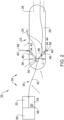
- Fig. 2 depicts the liquid tank assembly 20 in more detail.
- the liquid tank assembly 20 comprises a liquid tank 22.
- the liquid tank 22 has a tank wall 24 that encloses a tank volume 26 for storing a cryogenic liquid 28.
- the cryogenic liquid 28 has a liquid level L within the tank volume 26.
- the liquid level L is to be gauged by an optical level gauge apparatus 30.
- the optical level gauge apparatus 30 comprises a light source 32.
- the light source 32 emits at least one outgoing light ray 34.
- the outgoing light ray 34 may have a specific wavelength ⁇ .
- the light source 32 is a laser source, for example.
- the optical level gauge apparatus 30 further comprises a light conducting device 36.
- the light conducting device 36 may be configured as a fibre optic cable or a fiber bundle.
- the light conducting device 36 is optically coupled to the tank volume 26, so as to conduct the outgoing light ray 34 from the light source 32 into the tank volume 26.
- the light conducting device 36 may comprise an output member 38.
- the output member 38 may comprise optical elements, such as a lense, a prism, a polarizer and the like.
- the output member 38 is configured to launch a plurality of the outgoing light rays 34 into the tank volume 26 towards a tank wall circumferential portion 40 of the tank wall 24.
- the light source 32 is configured to emit two different discrete wavelengths ⁇ 1, ⁇ 2.
- the output member 38 may be configured such that outgoing light rays 34 having different wavelengths ⁇ 1, ⁇ 2 impinge on different tank wall circumferential portions 40 that are spaced apart along the tank longitudinal axis. With this configuration, it is possible to detect pitching of the liquid tank 22, as explained later.
- a first outgoing light ray 42 propagates through gas without being refracted and impinges on the tank wall circumferential portion 40.
- a second outgoing light ray 44 initially propagates through gas evaporating from the cryogenic liquid 28, before entering the cryogenic liquid 28, thereby being refracted at the liquid surface 46 and subsequently propagating through the cryogenic liquid 28 towards another tank wall circumferential portion 40.
- the first and second outgoing light rays 42, 44 are backscattered from the tank wall circumferential portion 40, each forming an incoming light ray 48.
- the tank wall 24 may have an interior reflective coating that is arranged at the tank wall circumferential portions 40, so as to improve backscattering. It is also possible that the tank wall 24 is structured so as to favor backscattering of the outgoing light rays 34.
- An example for a suitable structure is a reflective grating.
- the light conducting device 36 may further comprise an input member 50.
- the input member 50 may include optical elements.
- the output member 38 and the input member 50 need not necessarily be separate units, they may be integrated into a single unit and designated input/output member.
- the input member 50 preferably receives the incoming light rays 48 and couples the incoming light rays 48 into a single bidirectional light conductor 52 of the light conducting device 36. It should be noted that the bidirectional light conductor 52 is also optically coupled to the light source 32, so as to conduct the outgoing light rays 34 from the light source 32 towards the tank volume 26. It is further noted, that incoming and outgoing light rays 34, 48 may be conducted within a separate outgoing light conductor and incoming light conductor, respectively, of the light conducting device 36.
- the optical level gauge apparatus 30 further comprises a sensor device 54.
- the sensor device 54 is optically coupled to the light conducting device 36, so as to be able to receive the incoming light rays 48.
- the sensor device 54 comprises a plurality of optical sensors 56.
- the optical sensors 56 may be individual sensors, such as photodiodes, phototransistors, etc., or may be integrated into an optical chip, such as a CCD-chip or other imaging chip.
- the light conducting device 36 is optically coupled to the sensor device 54 in a manner so that each optical sensor 56 corresponds to a specific tank wall portion 58. This may, for example, be achieved by individually routing optical fibres of the light conducting device 36 towards each optical sensor 56.
- the sensor device 54 is configured to output measured light values that are indicative of the amount of light being detected by each optical sensor 56.
- the measured light values can be processed further by a data processing device, such as a microcontroller, microprocessor or other computing device.
- the optical level gauge apparatus 30 further comprises a liquid level determining device 60.
- the liquid level determining device 60 is configured to process the output of the sensor device 54 using signal processing techniques, that are known per se. After processing, the liquid level determining device 60 outputs a liquid level value, that is indicative of the liquid level L within the tank volume 26.
- the liquid level determining device 60 may be realized by a suitable data processing device, such as a microcontroller or microprocessor, an embedded system or by a general-purpose computer.
- FIG. 3 top left diagram, depicts a schematic view of the liquid tank 22 along its axial direction, i.e., its longitudinal axis. Furthermore, this diagram depicts the plurality of specific tank wall portions 58 that are distributed along the circumferential direction of the liquid tank 22 with an equal distance to each other. Each specific tank wall portion 58 corresponds to exactly one optical sensor 56. The diagram also depicts the liquid level L and two of the specific tank wall portions 58 as reference points 62, in order to facilitate the explanation.
- Fig. 3 top right diagram, depicts a schematic longitudinal cross section of the liquid tank 22.
- the outgoing and incoming light rays 34, 48 are depicted. It should be noted that the angle of refraction is greatly exaggerated in order to facilitate understanding of the measurement principle.
- Fig. 3 bottom diagram, depicts on the x-axis the sensor index, i.e. the number of the optical sensor 56 counted from a starting point.
- the y-axis depicts the attenuation of the incoming light ray 48 in a decibel scale.
- the baseline for this scale is for example given by the outgoing light ray 34.
- the liquid level L can be determined by determining the sensor index of the optical sensors 56 which begin to show less attenuation, as indicated by the arrows in Fig. 3 , bottom diagram. Since the specific tank wall portions 58 are uniquely related with the optical sensors 56 and the position of the specific tank wall portion 58 and the geometry of the tank volume 26 are known, the liquid level determining device 60 is able to calculate the position of the liquid surface 46 and hence determine the liquid level L in the tank volume 26.
- Fig. 4 top diagram, depicts the total path absorption, i.e., an absorption value, depending on the sensor index of the optical sensor 56.
- the total path absorption is shown in linear scale. Hence, points further along the y-axis designate a larger total path absorption than points closer to the x-axis, resulting in the absorption curves 65 for different fill levels I, II, ..., X of the tank volume 26.
- Fill levels I, II, ..., V are below 50 % fill level, while VI, VII, ..., X are above 50 % fill level.
- the light conducting device 36 is arranged at the 50 % level.
- Fig. 4 middle diagram, depicts the gradient of the total path absorption depicted in Fig. 4 , top diagram. With this it is easier to detect the sensor index, at which the absorption value increases/decreases so that the liquid level L may be determined more precisely.
- Fig. 4 bottom diagram, depicts absorption curves 65 for different degrees 0°, ⁇ 15°, ⁇ 30° of rotation of the liquid tank 22 about its longitudinal axis, i.e. if the aircraft 10 rolls. As illustrated, all absorption curves 65 reach the same maximum, however the sensor index of the optical sensors 56 at which the respective absorption curve 65 begins to increase/decrease changes depending on the angle of rotation about the longitudinal axis.
- Fig. 5 depicts another embodiment of a liquid tank assembly 20. This embodiment is described only insofar as it differs from the embodiment previously described.
- the optical level gauge apparatus 30 comprises a light source 32 that is capable of emitting a plurality of wavelengths, specifically two or more discrete wavelengths, or a continuous spectrum such as white light.
- the light source 32 may be configured as a laser source.
- the light conducting device 36 is configured as an imaging light conducting device that allows imaging the tank volume 26 by a corresponding sensor device 54.
- the output member 38 may be configured to output the outgoing light rays 34 so as to form a pattern arrangement 66.
- the pattern arrangement 66 is projected onto the inner surface of the tank wall 24 and may be comprised of axial and circumferential stripes as exemplified in Fig. 6 to Fig. 8 .
- the light source 32 may be optically coupled to the tank volume 26 by the light conducting device 36 such that the tank wall 24 may be illuminated. It is also possible that the tank wall 24 has the pattern arrangement 66 formed thereon. Furthermore, the tank wall 24 may comprise at least one anti-sloshing baffle 68 and the pattern arrangement 66 is disposed on or projected onto the anti-sloshing baffle 68.
- the input member 50 is configured such that an image of the tank volume 26 is passively conducted towards the sensor device 54, including backscattered or backreflected incoming light rays 48.
- the light conducting device 36 preferably comprises an outgoing light conductor 70 that is optically connected to the light source 32 and the output member 38 and conducts the outgoing light rays 34 from the light source 32 into the tank volume 26.
- the light conducting device 36 also comprises an incoming light conductor 72 that is configured as an imaging light conductor.
- the input member 50 may include optical elements that improve or facilitate imaging of the tank volume 26.
- the input member 50 is optically connected to the incoming light conductor 72, which in turn is connected to the optical sensor 56 of the sensor device 54.
- the optical sensors 56 form an imaging sensor, and the sensor device 54 is configured to output image data.
- the liquid level determining device 60 includes a computer vision algorithm for evaluating the image data detected by the sensor device 54 and may specifically search and determine distortions due to refraction or color changes of the pattern arrangement 66 in view of the liquid surface 46. It is possible to dye the liquid in the liquid tank 22 in order to improve contrast and measurement reliability. Through, for example, edge detection algorithms, and other computer vision algorithms that are known in a manner per se, the pattern arrangement 66 can be analysed and compared to the pattern arrangement 66 in a reference setup. By comparing the measured and the reference pattern arrangement 66, the liquid level L can be determined.
- this embodiment may also be used to inspect the tank volume 26 for defects by illuminating the tank wall 26 and imaging the tank wall 26 using the sensor device 54. Again computer vision algorithms may be used to detect leaks or other defects.
- Fig. 6 exemplifies the image of the tank volume 26, when the liquid tank assembly 20 is about half filled and in a neutral position, i.e., the liquid tank 22 is horizontally aligned.
- Fig. 7 depicts a similar situation, in which the liquid tank assembly 20 is aligned horizontally, however, the liquid tank 22 is rolled about its longitudinal axis.
- Fig. 8 depicts a situation, in which the aircraft 10 and consequently the liquid tank assembly 20 are pitched.
- the image of the pattern arrangement 66 changes depending on the current situation, so that as a result not only the liquid level L, but also pitching and rolling can be detected.
- Fig. 9 depicts an embodiment of an optical coupler assembly 74.
- the optical coupler assembly comprises an optical window 76 that may be attached to or integrated into the tank wall 24, preferably at a position, which allows the sensor device 45 to image a large portion of the tank volume 26.
- the optical coupler assembly 74 comprises an alignment flange 78, that is configured such that the light conducting device 36, specifically the input/output member can only be inserted in a manner, that allows meaningful imaging of the tank volume 26.
- the light conducting device 36 may comprise an alignment ring 80 that matches the alignment flange 78.
- the alignment flange 78 and the alignment ring 80 are configured such that they magnetically interact and hold firm the light conducting device 36.
- the optical coupler assembly 74 may further comprise a feedthrough guiding tube 82 that feeds the light conducting device 36 into the liquid tank 22 close to the tank volume 26, such that the optical level gauge apparatus can perform its function.
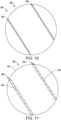
- Fig. 10 depicts schematically a tank wall portion 84 that is arranged opposite the light conducting device 36.
- the tank wall portion 84 comprises the pattern arrangement 66, which in this instance is configured to include two parallel slanted stripes 86.
- the pattern arrangement 66 includes a reflective material, that upon being illuminated by the light source 38 reflects the outgoing light rays 34 as incoming light rays 48 back towards the light conducting device 36 along the longitudinal axis of the tank 22.
- Fig. 10 shows the stripes without being illuminated. The back reflection may be diffuse or specular, whereas the latter case may be realized by reflection gratings.
- Fig. 11 illustrates the tank volume 26 being completely filled, wherein the pattern arrangement 66 is illuminated by the light source 32 and the reflected incoming light rays 48 are detected by the sensor device 54.
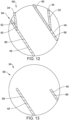
- Fig. 12 and Fig. 13 illustrate what happens when the liquid level L drops.
- Fig. 12 depicts the positions of the outgoing light rays 34. Due to the propagation within the cryogenic liquid 28, the outgoing light rays 34 illuminate the pattern arrangement 66 in a bottom section 88 below the liquid level L. Due to refraction at the liquid surface 46, however, the outgoing light rays 34 failed to illuminate the pattern arrangement 66 in a top section 90 and are instead hitting a tank wall section 92 next to the pattern arrangement 66.
- Fig. 13 illustrates the actual image, that would be recorded by the sensor device 54 in this case. Only the bottom section 88 is visible, and the liquid level L can be directly read of the illuminated pattern arrangement 66.
- the invention provides an apparatus and method for determining the liquid level L.
- light source emits outgoing light rays 34 that are back reflected by the tank wall 24 of the liquid tank 22.
- the back reflected incoming light rays are received by a light conducting device 36, which conducts the incoming light rays 48 towards a sensor device 54.
- the sensor device 54 has optical sensors 56 that are coupled to the light conducting device 36 in such a manner that there is a one-two-one relationship between each optical sensor 56 and a specific tank wall portion 58. Due to the change in the amount of light that is received by the optical sensor 56 after the outgoing light rays 34 were refracted by the liquid surface 46, the liquid level determining device 60 is capable of determining the liquid level L.
Landscapes
- Physics & Mathematics (AREA)
- Electromagnetism (AREA)
- Engineering & Computer Science (AREA)
- Thermal Sciences (AREA)
- Fluid Mechanics (AREA)
- General Physics & Mathematics (AREA)
- Aviation & Aerospace Engineering (AREA)
- Mechanical Engineering (AREA)
- Measurement Of Levels Of Liquids Or Fluent Solid Materials (AREA)
Priority Applications (3)
| Application Number | Priority Date | Filing Date | Title |
|---|---|---|---|
| EP21209235.7A EP4184131B1 (fr) | 2021-11-19 | 2021-11-19 | Appareil et procédé de jauge de niveau optique, ensemble de réservoir de liquide et véhicule l'utilisant |
| CN202211444317.5A CN116182987A (zh) | 2021-11-19 | 2022-11-18 | 光学液位计设备和方法、液体罐组件和使用其的载具 |
| US17/989,901 US12545425B2 (en) | 2021-11-19 | 2022-11-18 | Optical level gauge apparatus and method, liquid tank assembly and vehicle employing the same |
Applications Claiming Priority (1)
| Application Number | Priority Date | Filing Date | Title |
|---|---|---|---|
| EP21209235.7A EP4184131B1 (fr) | 2021-11-19 | 2021-11-19 | Appareil et procédé de jauge de niveau optique, ensemble de réservoir de liquide et véhicule l'utilisant |
Publications (2)
| Publication Number | Publication Date |
|---|---|
| EP4184131A1 true EP4184131A1 (fr) | 2023-05-24 |
| EP4184131B1 EP4184131B1 (fr) | 2025-09-03 |
Family
ID=78709284
Family Applications (1)
| Application Number | Title | Priority Date | Filing Date |
|---|---|---|---|
| EP21209235.7A Active EP4184131B1 (fr) | 2021-11-19 | 2021-11-19 | Appareil et procédé de jauge de niveau optique, ensemble de réservoir de liquide et véhicule l'utilisant |
Country Status (3)
| Country | Link |
|---|---|
| US (1) | US12545425B2 (fr) |
| EP (1) | EP4184131B1 (fr) |
| CN (1) | CN116182987A (fr) |
Families Citing this family (5)
| Publication number | Priority date | Publication date | Assignee | Title |
|---|---|---|---|---|
| CA3206426A1 (fr) * | 2022-10-31 | 2024-04-30 | Agco Corporation | Systeme de determination de volume, vehicule comprenant le systeme de determination de volume et methodes d~exploitation d~un tel vehicule |
| US12623673B2 (en) | 2023-06-29 | 2026-05-12 | Torc Robotics, Inc. | Systems and methods of detecting fluid release |
| US12626545B2 (en) | 2023-06-29 | 2026-05-12 | Torc Robotics, Inc. | Systems and methods of detecting fluid release |
| US12546269B2 (en) * | 2023-06-30 | 2026-02-10 | Torc Robotics, Inc. | Systems and methods of detecting fluid release |
| DE102023121539A1 (de) * | 2023-08-11 | 2025-02-13 | Technische Universität Dresden, Körperschaft des öffentlichen Rechts | Bauraumangepasster Wasserstofftank |
Citations (8)
| Publication number | Priority date | Publication date | Assignee | Title |
|---|---|---|---|---|
| US5973770A (en) * | 1998-05-06 | 1999-10-26 | Quantum Imaging, Inc. | Method for measuring the relative proximity of and interacting with a plurality of media/molecular structures |
| US20050242117A1 (en) * | 2004-02-06 | 2005-11-03 | Goro Yoshida | Liquid dispensing apparatus, automatic analyzer using same, and liquid surface detecting apparatus |
| US8159660B2 (en) * | 2008-04-04 | 2012-04-17 | Leddartech Inc. | Optical level measurement device and method |
| US9074921B1 (en) | 2013-01-03 | 2015-07-07 | The United States Of America As Represented By The Administrator Of The National Aeronautics And Space Administration | Cryogenic liquid level sensor apparatus and method |
| US20170230635A1 (en) * | 2016-02-04 | 2017-08-10 | Simmonds Precision Products, Inc. | Imaging system for fuel tank analysis |
| DE102017205981A1 (de) * | 2017-04-07 | 2018-10-11 | Robert Bosch Gmbh | Messvorrichtung und Messverfahren zur Überwachung einer Flüssigkeit in einem Flüssigkeitstank sowie Flüssigkeitstank |
| DE102018200363B3 (de) * | 2018-01-11 | 2019-03-21 | Robert Bosch Gmbh | Messvorrichtung zur Füllstandüberwachung und differenziellen Messung des optischen Brechungsindex |
| WO2020003303A2 (fr) * | 2018-06-28 | 2020-01-02 | Ormetrix Sensing Technologies Ltd | Système de jaugeage de volume de fluides |
Family Cites Families (9)
| Publication number | Priority date | Publication date | Assignee | Title |
|---|---|---|---|---|
| US6274880B1 (en) * | 1998-07-31 | 2001-08-14 | Hewlett-Packard Company | Fluid level sensing system and method having controlled surface pairs |
| WO2007142933A2 (fr) * | 2006-05-31 | 2007-12-13 | Giraffe Liquid Management Systems, Inc. | Détecteurs de niveau de liquide et systèmes pour les utiliser |
| US7635854B1 (en) * | 2008-07-09 | 2009-12-22 | Institut National D'optique | Method and apparatus for optical level sensing of agitated fluid surfaces |
| EP2351997A4 (fr) * | 2008-10-28 | 2017-12-27 | Northeastern University | Dispositif pour mesurer un niveau de métal fondu et procédé pour celui-ci |
| EP2685226B1 (fr) * | 2012-07-11 | 2019-02-27 | AIRBUS HELICOPTERS DEUTSCHLAND GmbH | Capteur de niveau liquide optique |
| US10053269B2 (en) * | 2015-02-09 | 2018-08-21 | The Boeing Company | Multi-functional fiber optic fuel sensor system having a photonic membrane |
| US10371559B2 (en) * | 2017-04-17 | 2019-08-06 | The Boeing Company | Differential spectral liquid level sensor |
| US10352755B2 (en) * | 2017-04-17 | 2019-07-16 | The Boeing Company | Passive differential liquid level sensor using optical fibers |
| US10935413B2 (en) * | 2019-04-10 | 2021-03-02 | The Boeing Company | Non-contact time-of-flight fuel level sensor using plastic optical fiber |
-
2021
- 2021-11-19 EP EP21209235.7A patent/EP4184131B1/fr active Active
-
2022
- 2022-11-18 CN CN202211444317.5A patent/CN116182987A/zh active Pending
- 2022-11-18 US US17/989,901 patent/US12545425B2/en active Active
Patent Citations (8)
| Publication number | Priority date | Publication date | Assignee | Title |
|---|---|---|---|---|
| US5973770A (en) * | 1998-05-06 | 1999-10-26 | Quantum Imaging, Inc. | Method for measuring the relative proximity of and interacting with a plurality of media/molecular structures |
| US20050242117A1 (en) * | 2004-02-06 | 2005-11-03 | Goro Yoshida | Liquid dispensing apparatus, automatic analyzer using same, and liquid surface detecting apparatus |
| US8159660B2 (en) * | 2008-04-04 | 2012-04-17 | Leddartech Inc. | Optical level measurement device and method |
| US9074921B1 (en) | 2013-01-03 | 2015-07-07 | The United States Of America As Represented By The Administrator Of The National Aeronautics And Space Administration | Cryogenic liquid level sensor apparatus and method |
| US20170230635A1 (en) * | 2016-02-04 | 2017-08-10 | Simmonds Precision Products, Inc. | Imaging system for fuel tank analysis |
| DE102017205981A1 (de) * | 2017-04-07 | 2018-10-11 | Robert Bosch Gmbh | Messvorrichtung und Messverfahren zur Überwachung einer Flüssigkeit in einem Flüssigkeitstank sowie Flüssigkeitstank |
| DE102018200363B3 (de) * | 2018-01-11 | 2019-03-21 | Robert Bosch Gmbh | Messvorrichtung zur Füllstandüberwachung und differenziellen Messung des optischen Brechungsindex |
| WO2020003303A2 (fr) * | 2018-06-28 | 2020-01-02 | Ormetrix Sensing Technologies Ltd | Système de jaugeage de volume de fluides |
Non-Patent Citations (2)
| Title |
|---|
| DILLER: "Refractive Index of Gaseous and Liquid Hydrogen", J. CHEM. PHYS, vol. 49, 1968, pages 3096, Retrieved from the Internet <URL:https://doi.org/10.1063/1.1670554> |
| GROSSLE: "Minimal and complete set of descriptors for IR-absorption spectra of liquid H2-D2 mixtures", AIP ADVANCES, vol. 10, 2020, pages 055108, XP012247409, Retrieved from the Internet <URL:https://doi.org/10.1063/l5111000> DOI: 10.1063/1.5111000 |
Also Published As
| Publication number | Publication date |
|---|---|
| US20230159182A1 (en) | 2023-05-25 |
| CN116182987A (zh) | 2023-05-30 |
| EP4184131B1 (fr) | 2025-09-03 |
| US12545425B2 (en) | 2026-02-10 |
Similar Documents
| Publication | Publication Date | Title |
|---|---|---|
| US12545425B2 (en) | Optical level gauge apparatus and method, liquid tank assembly and vehicle employing the same | |
| US10928303B2 (en) | Concentration measuring device | |
| US4943157A (en) | Fiber optic triangulation gage | |
| CA2272033A1 (fr) | Disposition pour determiner les fluctuations de contraintes sur une fibre optique et sa temperature | |
| US9116029B2 (en) | Optical liquid level sensor having a plurality of optical fibers | |
| CN104335067A (zh) | 坐标测量系统与方法 | |
| CN105865578A (zh) | 具有光子膜的多功能纤维光学燃油传感器系统 | |
| CN106017340A (zh) | 一种基于机器视觉的透光容器壁厚检测装置及方法 | |
| US20180259551A1 (en) | Fiber-Optic Accelerometer | |
| US11989346B2 (en) | Fiber-optic sensor, data glove and method for detecting curvature | |
| CN108507597A (zh) | 光纤法珀传感器解调装置及方法 | |
| JP6322483B2 (ja) | 曲率センサ、内視鏡装置 | |
| US10222607B2 (en) | Three-dimensional endoscope | |
| US10401140B2 (en) | Bending detecting system, light guide body, tubular apparatus, light detecting apparatus, light detecting method, and optical bending measuring apparatus | |
| EP0079944A1 (fr) | Interferometre a fibre optique. | |
| US6329660B1 (en) | Method of deriving sunlight induced fluorescence from radiance measurements and devices for executing the method | |
| GB2105034A (en) | Fiber optic impurity detector | |
| US9267788B2 (en) | Optical sensor having light guide members with characteristic detection portions whose optical charateristics vary in accordance with a physicochemical state | |
| US20120092673A1 (en) | Device and method for optically detecting gas | |
| JPH068724B2 (ja) | 光学的検出装置 | |
| JPH01197632A (ja) | 流体屈折計およびこれを用いた流体密度計 | |
| US10627346B2 (en) | Refractive index measuring device and refractive index measuring method | |
| US9255876B2 (en) | Temperature sensor and method for measuring a temperature change | |
| US20240263937A1 (en) | Measurement head | |
| US12152973B2 (en) | Apparatus and method for detecting objects |
Legal Events
| Date | Code | Title | Description |
|---|---|---|---|
| PUAI | Public reference made under article 153(3) epc to a published international application that has entered the european phase |
Free format text: ORIGINAL CODE: 0009012 |
|
| STAA | Information on the status of an ep patent application or granted ep patent |
Free format text: STATUS: THE APPLICATION HAS BEEN PUBLISHED |
|
| AK | Designated contracting states |
Kind code of ref document: A1 Designated state(s): AL AT BE BG CH CY CZ DE DK EE ES FI FR GB GR HR HU IE IS IT LI LT LU LV MC MK MT NL NO PL PT RO RS SE SI SK SM TR |
|
| STAA | Information on the status of an ep patent application or granted ep patent |
Free format text: STATUS: REQUEST FOR EXAMINATION WAS MADE |
|
| 17P | Request for examination filed |
Effective date: 20231124 |
|
| RBV | Designated contracting states (corrected) |
Designated state(s): AL AT BE BG CH CY CZ DE DK EE ES FI FR GB GR HR HU IE IS IT LI LT LU LV MC MK MT NL NO PL PT RO RS SE SI SK SM TR |
|
| GRAP | Despatch of communication of intention to grant a patent |
Free format text: ORIGINAL CODE: EPIDOSNIGR1 |
|
| STAA | Information on the status of an ep patent application or granted ep patent |
Free format text: STATUS: GRANT OF PATENT IS INTENDED |
|
| INTG | Intention to grant announced |
Effective date: 20240327 |
|
| GRAJ | Information related to disapproval of communication of intention to grant by the applicant or resumption of examination proceedings by the epo deleted |
Free format text: ORIGINAL CODE: EPIDOSDIGR1 |
|
| STAA | Information on the status of an ep patent application or granted ep patent |
Free format text: STATUS: REQUEST FOR EXAMINATION WAS MADE |
|
| INTC | Intention to grant announced (deleted) | ||
| GRAP | Despatch of communication of intention to grant a patent |
Free format text: ORIGINAL CODE: EPIDOSNIGR1 |
|
| STAA | Information on the status of an ep patent application or granted ep patent |
Free format text: STATUS: GRANT OF PATENT IS INTENDED |
|
| INTG | Intention to grant announced |
Effective date: 20241009 |
|
| GRAJ | Information related to disapproval of communication of intention to grant by the applicant or resumption of examination proceedings by the epo deleted |
Free format text: ORIGINAL CODE: EPIDOSDIGR1 |
|
| STAA | Information on the status of an ep patent application or granted ep patent |
Free format text: STATUS: REQUEST FOR EXAMINATION WAS MADE |
|
| INTC | Intention to grant announced (deleted) | ||
| GRAP | Despatch of communication of intention to grant a patent |
Free format text: ORIGINAL CODE: EPIDOSNIGR1 |
|
| STAA | Information on the status of an ep patent application or granted ep patent |
Free format text: STATUS: GRANT OF PATENT IS INTENDED |
|
| INTG | Intention to grant announced |
Effective date: 20250328 |
|
| GRAS | Grant fee paid |
Free format text: ORIGINAL CODE: EPIDOSNIGR3 |
|
| GRAA | (expected) grant |
Free format text: ORIGINAL CODE: 0009210 |
|
| STAA | Information on the status of an ep patent application or granted ep patent |
Free format text: STATUS: THE PATENT HAS BEEN GRANTED |
|
| AK | Designated contracting states |
Kind code of ref document: B1 Designated state(s): AL AT BE BG CH CY CZ DE DK EE ES FI FR GB GR HR HU IE IS IT LI LT LU LV MC MK MT NL NO PL PT RO RS SE SI SK SM TR |
|
| REG | Reference to a national code |
Ref country code: CH Ref legal event code: EP |
|
| REG | Reference to a national code |
Ref country code: DE Ref legal event code: R096 Ref document number: 602021037629 Country of ref document: DE |
|
| REG | Reference to a national code |
Ref country code: IE Ref legal event code: FG4D |
|
| REG | Reference to a national code |
Ref country code: NL Ref legal event code: MP Effective date: 20250903 |
|
| PGFP | Annual fee paid to national office [announced via postgrant information from national office to epo] |
Ref country code: DE Payment date: 20251119 Year of fee payment: 5 |
|
| PGFP | Annual fee paid to national office [announced via postgrant information from national office to epo] |
Ref country code: GB Payment date: 20251121 Year of fee payment: 5 |
|
| PG25 | Lapsed in a contracting state [announced via postgrant information from national office to epo] |
Ref country code: NO Free format text: LAPSE BECAUSE OF FAILURE TO SUBMIT A TRANSLATION OF THE DESCRIPTION OR TO PAY THE FEE WITHIN THE PRESCRIBED TIME-LIMIT Effective date: 20251203 |
|
| REG | Reference to a national code |
Ref country code: LT Ref legal event code: MG9D |
|
| PG25 | Lapsed in a contracting state [announced via postgrant information from national office to epo] |
Ref country code: FI Free format text: LAPSE BECAUSE OF FAILURE TO SUBMIT A TRANSLATION OF THE DESCRIPTION OR TO PAY THE FEE WITHIN THE PRESCRIBED TIME-LIMIT Effective date: 20250903 |
|
| PG25 | Lapsed in a contracting state [announced via postgrant information from national office to epo] |
Ref country code: HR Free format text: LAPSE BECAUSE OF FAILURE TO SUBMIT A TRANSLATION OF THE DESCRIPTION OR TO PAY THE FEE WITHIN THE PRESCRIBED TIME-LIMIT Effective date: 20250903 |
|
| PGFP | Annual fee paid to national office [announced via postgrant information from national office to epo] |
Ref country code: FR Payment date: 20251126 Year of fee payment: 5 |
|
| PG25 | Lapsed in a contracting state [announced via postgrant information from national office to epo] |
Ref country code: GR Free format text: LAPSE BECAUSE OF FAILURE TO SUBMIT A TRANSLATION OF THE DESCRIPTION OR TO PAY THE FEE WITHIN THE PRESCRIBED TIME-LIMIT Effective date: 20251204 |
|
| PG25 | Lapsed in a contracting state [announced via postgrant information from national office to epo] |
Ref country code: SE Free format text: LAPSE BECAUSE OF FAILURE TO SUBMIT A TRANSLATION OF THE DESCRIPTION OR TO PAY THE FEE WITHIN THE PRESCRIBED TIME-LIMIT Effective date: 20250903 |
|
| PG25 | Lapsed in a contracting state [announced via postgrant information from national office to epo] |
Ref country code: LV Free format text: LAPSE BECAUSE OF FAILURE TO SUBMIT A TRANSLATION OF THE DESCRIPTION OR TO PAY THE FEE WITHIN THE PRESCRIBED TIME-LIMIT Effective date: 20250903 |
|
| PG25 | Lapsed in a contracting state [announced via postgrant information from national office to epo] |
Ref country code: BG Free format text: LAPSE BECAUSE OF FAILURE TO SUBMIT A TRANSLATION OF THE DESCRIPTION OR TO PAY THE FEE WITHIN THE PRESCRIBED TIME-LIMIT Effective date: 20250903 Ref country code: PL Free format text: LAPSE BECAUSE OF FAILURE TO SUBMIT A TRANSLATION OF THE DESCRIPTION OR TO PAY THE FEE WITHIN THE PRESCRIBED TIME-LIMIT Effective date: 20250903 |
|
| PG25 | Lapsed in a contracting state [announced via postgrant information from national office to epo] |
Ref country code: RS Free format text: LAPSE BECAUSE OF FAILURE TO SUBMIT A TRANSLATION OF THE DESCRIPTION OR TO PAY THE FEE WITHIN THE PRESCRIBED TIME-LIMIT Effective date: 20251203 |
|
| PG25 | Lapsed in a contracting state [announced via postgrant information from national office to epo] |
Ref country code: ES Free format text: LAPSE BECAUSE OF FAILURE TO SUBMIT A TRANSLATION OF THE DESCRIPTION OR TO PAY THE FEE WITHIN THE PRESCRIBED TIME-LIMIT Effective date: 20250903 |
|
| REG | Reference to a national code |
Ref country code: AT Ref legal event code: MK05 Ref document number: 1833547 Country of ref document: AT Kind code of ref document: T Effective date: 20250903 |
|
| PG25 | Lapsed in a contracting state [announced via postgrant information from national office to epo] |
Ref country code: NL Free format text: LAPSE BECAUSE OF FAILURE TO SUBMIT A TRANSLATION OF THE DESCRIPTION OR TO PAY THE FEE WITHIN THE PRESCRIBED TIME-LIMIT Effective date: 20250903 |
|
| PG25 | Lapsed in a contracting state [announced via postgrant information from national office to epo] |
Ref country code: SM Free format text: LAPSE BECAUSE OF FAILURE TO SUBMIT A TRANSLATION OF THE DESCRIPTION OR TO PAY THE FEE WITHIN THE PRESCRIBED TIME-LIMIT Effective date: 20250903 |
|
| PG25 | Lapsed in a contracting state [announced via postgrant information from national office to epo] |
Ref country code: AT Free format text: LAPSE BECAUSE OF FAILURE TO SUBMIT A TRANSLATION OF THE DESCRIPTION OR TO PAY THE FEE WITHIN THE PRESCRIBED TIME-LIMIT Effective date: 20250903 |
|
| PG25 | Lapsed in a contracting state [announced via postgrant information from national office to epo] |
Ref country code: RO Free format text: LAPSE BECAUSE OF FAILURE TO SUBMIT A TRANSLATION OF THE DESCRIPTION OR TO PAY THE FEE WITHIN THE PRESCRIBED TIME-LIMIT Effective date: 20250903 Ref country code: IT Free format text: LAPSE BECAUSE OF FAILURE TO SUBMIT A TRANSLATION OF THE DESCRIPTION OR TO PAY THE FEE WITHIN THE PRESCRIBED TIME-LIMIT Effective date: 20250903 |
|
| PG25 | Lapsed in a contracting state [announced via postgrant information from national office to epo] |
Ref country code: IS Free format text: LAPSE BECAUSE OF FAILURE TO SUBMIT A TRANSLATION OF THE DESCRIPTION OR TO PAY THE FEE WITHIN THE PRESCRIBED TIME-LIMIT Effective date: 20260103 |
|
| PG25 | Lapsed in a contracting state [announced via postgrant information from national office to epo] |
Ref country code: PT Free format text: LAPSE BECAUSE OF FAILURE TO SUBMIT A TRANSLATION OF THE DESCRIPTION OR TO PAY THE FEE WITHIN THE PRESCRIBED TIME-LIMIT Effective date: 20260105 Ref country code: CZ Free format text: LAPSE BECAUSE OF FAILURE TO SUBMIT A TRANSLATION OF THE DESCRIPTION OR TO PAY THE FEE WITHIN THE PRESCRIBED TIME-LIMIT Effective date: 20250903 |
|
| PG25 | Lapsed in a contracting state [announced via postgrant information from national office to epo] |
Ref country code: EE Free format text: LAPSE BECAUSE OF FAILURE TO SUBMIT A TRANSLATION OF THE DESCRIPTION OR TO PAY THE FEE WITHIN THE PRESCRIBED TIME-LIMIT Effective date: 20250903 Ref country code: SK Free format text: LAPSE BECAUSE OF FAILURE TO SUBMIT A TRANSLATION OF THE DESCRIPTION OR TO PAY THE FEE WITHIN THE PRESCRIBED TIME-LIMIT Effective date: 20250903 |