EP4184183B1 - Erkennung des offenen oder geschlossenen zustandes eines leistungsschalters - Google Patents
Erkennung des offenen oder geschlossenen zustandes eines leistungsschalters Download PDFInfo
- Publication number
- EP4184183B1 EP4184183B1 EP22207560.8A EP22207560A EP4184183B1 EP 4184183 B1 EP4184183 B1 EP 4184183B1 EP 22207560 A EP22207560 A EP 22207560A EP 4184183 B1 EP4184183 B1 EP 4184183B1
- Authority
- EP
- European Patent Office
- Prior art keywords
- meter
- test signal
- voltage level
- phase
- injection
- Prior art date
- Legal status (The legal status is an assumption and is not a legal conclusion. Google has not performed a legal analysis and makes no representation as to the accuracy of the status listed.)
- Active
Links
Images
Classifications
-
- G—PHYSICS
- G01—MEASURING; TESTING
- G01R—MEASURING ELECTRIC VARIABLES; MEASURING MAGNETIC VARIABLES
- G01R31/00—Arrangements for testing electric properties; Arrangements for locating electric faults; Arrangements for electrical testing characterised by what is being tested not provided for elsewhere
- G01R31/327—Testing of circuit interrupters, switches or circuit-breakers
- G01R31/3271—Testing of circuit interrupters, switches or circuit-breakers of high voltage or medium voltage devices
- G01R31/3272—Apparatus, systems or circuits therefor
- G01R31/3274—Details related to measuring, e.g. sensing, displaying or computing; Measuring of variables related to the contact pieces, e.g. wear, position or resistance
-
- G—PHYSICS
- G01—MEASURING; TESTING
- G01R—MEASURING ELECTRIC VARIABLES; MEASURING MAGNETIC VARIABLES
- G01R22/00—Arrangements for measuring time integral of electric power or current, e.g. electricity meters
- G01R22/06—Arrangements for measuring time integral of electric power or current, e.g. electricity meters by electronic methods
- G01R22/061—Details of electronic electricity meters
- G01R22/068—Arrangements for indicating or signaling faults
-
- G—PHYSICS
- G01—MEASURING; TESTING
- G01R—MEASURING ELECTRIC VARIABLES; MEASURING MAGNETIC VARIABLES
- G01R31/00—Arrangements for testing electric properties; Arrangements for locating electric faults; Arrangements for electrical testing characterised by what is being tested not provided for elsewhere
- G01R31/327—Testing of circuit interrupters, switches or circuit-breakers
-
- G—PHYSICS
- G01—MEASURING; TESTING
- G01R—MEASURING ELECTRIC VARIABLES; MEASURING MAGNETIC VARIABLES
- G01R19/00—Arrangements for measuring currents or voltages or for indicating presence or sign thereof
- G01R19/0084—Measuring voltage only
-
- G—PHYSICS
- G01—MEASURING; TESTING
- G01R—MEASURING ELECTRIC VARIABLES; MEASURING MAGNETIC VARIABLES
- G01R31/00—Arrangements for testing electric properties; Arrangements for locating electric faults; Arrangements for electrical testing characterised by what is being tested not provided for elsewhere
- G01R31/327—Testing of circuit interrupters, switches or circuit-breakers
- G01R31/3271—Testing of circuit interrupters, switches or circuit-breakers of high voltage or medium voltage devices
- G01R31/3275—Fault detection or status indication
Definitions
- the invention relates to the field of electric meters.
- Modern electricity meters are so-called “intelligent” electronic meters which are of course designed to measure electrical energy supplied by a distributor to an electrical installation via a distribution network, but which are also capable of performing a certain number of additional functions: rate management by receiving orders, remote reading and programming, remote customer information, etc.
- Some electric meters include a cut-off device (located inside the electric meter), which makes it possible to selectively connect and disconnect, remotely or from the electric meter, the electrical installation from the distribution network.
- the cutting device is used in particular to remotely cut off or restore the power supply to the installation in the event, for example, of termination of the subscription or non-compliance with the subscription contract.
- circuit breaker located outside and downstream of the electricity meter (i.e. on the installation side).
- the circuit breaker which can be activated by the subscriber, has the role of protecting the installation by opening when an overvoltage, resulting for example from a short circuit between a phase and the neutral, occurs on the network of distribution.
- the object of the invention is to detect from inside the meter, in a reliable and robust manner, the open or closed state of the circuit breaker while the meter cut-off member is open.
- the detection circuit of the meter according to the invention therefore makes it possible to detect, by injecting a test signal on the phase conductor, whether the circuit breaker is open or closed when the cut-off member is open.
- the difference in the intermediate voltage level, between the open circuit breaker and closed circuit breaker cases, is typically of the order of V or hundreds of mV, and is therefore easily measurable.
- the detection is less sensitive to noise and therefore more reliable and more robust than in the prior art.
- the injection component being a first capacitor integrated in a first high-pass filter making it possible to filter parasitic signals coming from the distribution network.
- the at least one generator component comprises a generator module arranged to produce the test signal with the predetermined voltage level, and a driver forming a current source arranged to ensure that the test signal is generated with a level of sufficient current to maintain, at the output of the at least one generator component, a voltage level equal to the predetermined voltage level.
- the measurement chain successively comprises, from upstream to downstream, a second high-pass filter, an envelope detector and a low-pass filter.
- the injection chain being arranged to, when the cut-off member is open, inject the test signal periodically, for a predetermined duration.
- the injection chain being arranged to, when the cut-off member is open, inject the test signal continuously.
- test signal is an alternating signal having a frequency at least one hundred times greater than a frequency of a phase current circulating on the phase of the distribution network.
- phase conductor is connected to an electrical mass of the meter upstream of the cutting member, the meter further comprising a second capacitor positioned upstream of the switching member. cut-off and having a first terminal connected to the neutral conductor and a second terminal connected to the phase conductor.
- the injection component being a first capacitor
- the injection chain comprising a resistor mounted between the first capacitor and an output of at least one generator component
- the injection component being a first capacitor
- the injection chain comprising a resistor mounted between the first capacitor and an output of at least one generator component
- a computer-readable recording medium is provided, on which the computer program as previously described is recorded.
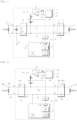
- the meter 1 is a single-phase meter, which is intended to measure electrical energy supplied to the electrical installation 2 of a subscriber by a distribution network 3.
- Distribution network 3 includes a phase 4 and a neutral 5.
- Circuit breaker 6 is positioned between meter 1 and installation 2.
- Meter 1 comprises an upstream phase port P connected to phase 4 and an upstream neutral port N connected to neutral 5.
- Meter 1 further comprises a downstream phase port P' and a downstream neutral port N'.
- the downstream phase port P' and the downstream neutral port N' of meter 1 are connected to installation 2 respectively via a switch 8 and a switch 9 integrated into circuit breaker 6.
- the meter 1 further comprises a phase conductor 10, which is connected to phase 4 of the distribution network 3 via the upstream phase port P, and which is connected to the circuit breaker 6 via the downstream phase port P'.
- the meter 1 further comprises a neutral conductor 11, which is connected to the neutral 5 via the upstream neutral port N, and which is connected to the circuit breaker 6 via the downstream neutral port N'.
- the counter 1 further comprises a cut-off member 12 comprising a switch 13 mounted on the phase conductor 10.
- the meter 1 includes an electrical ground 14.
- the phase conductor 10 is connected to the ground 14 near the upstream phase port P and upstream of the cutoff member 12. This grounding of the phase conductor 10 s 'explained by the fact that the meter 1 includes a current sensor, making it possible to measure the phase current circulating on phase 4, which is a shunt (not shown here), positioned on the phase conductor 10 upstream of the cutoff member 12. Without grounding the phase conductor 10, the voltage across the shunt would be of the order of that present between the phase and the neutral of the network 3, and therefore very high.
- phase conductor 10 makes it possible to obtain a low voltage across the shunt (here of the order of 3.3V maximum after the application of a gain knowing that the voltage across a shunt is of the order of 15 to 20mV for a current passing through it of 100A effective), which corresponds to the acceptable voltage range at the input of the metrology microcontroller (not shown here) integrated into the meter 1.
- Counter 1 also includes a detection circuit.
- the detection circuit includes an injection chain 15, a measurement chain 16, and a processing component.
- chain we mean a succession of one or more components (or functional modules) connected in series.
- the injection chain 15 comprises at least one generator component (in this case two generator components), a resistor R, and an injection component (in this case a first capacitor C1).
- the two generator components include a generator module 20, integrated into the application microcontroller 17 of counter 1, and a driver 21.
- the microcontroller 17 includes a PWM output 22 (for Pulse Width Modulation ) .
- the output of generator module 20 is connected to PWM output 22.
- Driver 21 here is an amplifier mounted as a follower. Output 22 of microcontroller 17 is connected to the non-inverting input of driver 21. The inverting input of driver 21 is connected to the output of driver 21.
- the output of driver 21 is connected to a first terminal of the resistor R, a second terminal of which is connected to a first terminal of the first capacitor C1.
- the second terminal of the first capacitor C1 is connected to the phase conductor 10 downstream of the cutoff member 12.
- the resistor R has a resistance value which is here equal to 1k ⁇ .
- the first capacitor C1 has a capacitance value which is here equal to 47nF.
- the first capacitor C1 is integrated into a first high-pass filter (filter R-C1) making it possible to filter spurious signals coming from the distribution network 3.
- the measurement chain 16 comprises the following elements, arranged successively from upstream to downstream: a second high-pass filter 24, an analog-digital converter (ADC) 25, an envelope detector 26 and a low-pass filter 27.
- ADC analog-digital converter
- the second high-pass filter 24 is therefore here an analog filter while the envelope detector 26 and the low-pass filter 27 are digital modules.
- the ADC 25, the envelope detector 26 and the low-pass filter 27 are here integrated into the microcontroller 17.
- the processing component of the detection circuit is here the microcontroller 17.
- the microcontroller 17 is adapted to execute program instructions to implement the detection method which will be described.
- the program is stored in a memory 28, which is integrated into or connected to the microcontroller 17.
- the counter 1 further comprises a second capacitor C2 positioned upstream of the cutoff member 12 and having a first terminal connected to the neutral conductor 11 and a second terminal connected to the phase conductor 10.
- the second capacitor C2 has a value of capacity typically equal to that of the first capacitor C1, that is to say here at 47nF.
- the second capacitor C2 thus positioned between the neutral conductor 11 and the phase conductor 10, makes it possible to constitute a controlled mass return path for the measurements carried out during detection (remember that the cut-off member 12 is open during detection).
- a test signal St is injected periodically and for a predetermined duration by the injection chain 15.
- the period is for example equal to 1s and the predetermined duration to 500ms, i.e. that is to say that, when the cutoff member 12 is open, the test signal St is injected for 500ms, every 1s.
- the injection chain 15 could, when the cutoff member 12 is open, inject the test signal St continuously.
- the generator module 20 of the microcontroller 17 produces the test signal St and applies it to output 22.
- the test signal St is here a square (or rectangular) alternating signal having a frequency advantageously at least one hundred times higher than the frequency of the phase current circulating on phase 4 of the distribution network 3.
- the frequency of the phase current is equal to 50Hz
- the frequency of the test signal St is equal to 10kHz.
- the test signal St is generated by the microcontroller 17 with a predetermined voltage level, here equal to 3.3V (peak to peak).
- test signal St is applied to the non-inverting input of driver 21 and is therefore reproduced on the output of driver 21.
- the driver 21 forms a current source providing a complementary current making it possible to ensure that the test signal St is generated with a current level sufficient to maintain, at the output of the generating components (that is to say here at the output of the driver 21), a voltage level equal to the predetermined voltage level.
- the driver 21 is necessary here, because the different elements constituting and connected to the injection chain 15 “draw” current that the microcontroller 17 is not capable of providing alone.
- the resistance R limits the current.
- the first capacitor C1 makes it possible to inject the test signal St, produced by the microcontroller 17 and the driver 21, onto the phase conductor 10 downstream of the cutoff member 12.
- the measuring chain 16 makes it possible to measure, at a measuring point Pm of the injection chain 15 located between the at least one generator component and the injection component, an intermediate voltage level of the test signal St.
- the measuring point Pm is here located between the resistor R and the first capacitor C1.
- the second high-pass filter 24 is here an active high-pass filter with a gain equal to 1.
- the cut-off frequency of the second high-pass filter 24 is typically equal to 5kHz.
- the second high-pass filter 24, located upstream of the CAN 25, makes it possible to eliminate the possible 50Hz (which can be captured by the antenna effect in the case where the cutting member 12 and circuit breaker 6 are both open) and possible disturbances coming from network 3.
- the second high-pass filter 24 therefore makes it possible to present an undisturbed signal to CAN 25. It is then sufficient to detect the envelope of this signal (via the digital envelope detector 26) and to digitally filter the output of the detector 26 by the low-pass filter 27, the cutoff frequency of which is typically equal to 10 Hz.
- the microcontroller 17 compares the measured intermediate voltage level of the test signal St with a predetermined threshold, and detects that the circuit breaker 6 is open when the intermediate voltage level of the test signal St is greater than the predetermined threshold, and that the circuit breaker 6 is closed when the intermediate voltage level of the test signal St is less than or equal to the predetermined threshold.
- the measured intermediate voltage level is equal to a high level Vh equal to 3.3V (that is to say at the predetermined voltage level Vp of the test signal St).
- Vb Vp * Z C1 + Z subscriber + Z C2 / / Z upstream / R + Z C1 + Z subscription nborn + Z C2 / / Z upstream ,
- Z(C1) is an impedance of the first capacitor
- Z(C2) is an impedance of the second capacitor
- Z(upstream) is an impedance between the phase and the neutral upstream of meter 1
- Z(subscriber) is an impedance between the phase and neutral downstream of meter 1, said impedances being estimated at a frequency of the test signal (that is to say at 10kHz).
- the predetermined threshold Sp is therefore between the high level Vh (here equal to the predetermined voltage level Vp) and the low level Vb.
- the low level here is equal to 1.06V.
- the PWM output 22 is at 0, so that no injection of the test signal St is applied at the measurement point. This is also always the case when the cutting member 12 is closed.
- the counter 101 is a three-phase counter.
- Each element represented on the figure 2 which is similar to an element of the figure 1 , is referenced by adding 100 to the reference of the figure 1 .
- the distribution network 103 comprises three phases 104_i (i varying from 1 to 3) and a neutral 105.
- the counter 101 For each phase 104_i, the counter 101 comprises an upstream phase port Pi connected to said phase 104_i, and a downstream phase port P'i.
- the meter 101 further includes an upstream neutral port N connected to neutral 105 and a downstream neutral port N'.
- the downstream phase ports P'i and the downstream neutral port N' of the meter 101 are connected to the installation 102, respectively via switches 108_i and a switch 109 integrated in the circuit breaker 106.
- the counter 101 further comprises, for each phase 104_i, a phase conductor 110_i connected to said phase 104_i via the associated upstream phase port Pi.
- the meter 101 also includes a neutral conductor 111 connected to the neutral 105 via the upstream neutral port N.
- the counter 101 further comprises a cut-off member 112 comprising, for each phase, a switch 113_i mounted on the associated phase conductor 110_i.
- the counter 101 further comprises a detection circuit making it possible to detect, when the cut-off member 112 is open, whether the circuit breaker 106 is open or closed.
- the counter 101 here only integrates a single detection circuit, connected to a single phase conductor 110_i (connected to the phase 104_i represented on the figure 2 ).
- the counter 101 could, however, perfectly integrate several detection circuits to confirm the result and thus improve the robustness of the detection.
- the counter detection circuit 101 operates in the same way as the counter detection circuit 1.
- the detection circuit comprises an injection chain 115 which includes the generator module 120 integrated in the application microcontroller 117 and the driver 121 (the two generator components), a first capacitor C1 (the injection component), and a resistor R mounted between the output of driver 121 and the first capacitor C1.
- the first capacitor C1 and the resistor R form a first high pass filter.
- the detection circuit also includes a measurement chain 116 comprising a second high-pass filter 124 (analog), an ADC 125, an envelope detector 126 (digital) and a low-pass filter 127 (digital).
- the detection circuit further comprises a processing component, in this case the microcontroller 117 (in which the ADC 125, the envelope detector 126 and the low-pass filter 127 are integrated).
- a processing component in this case the microcontroller 117 (in which the ADC 125, the envelope detector 126 and the low-pass filter 127 are integrated).
- the current sensor used to measure the phase current circulating on said phase 104_i is a toroid and not a shunt.
- the neutral conductor 105 can therefore be grounded (electrical ground 114) which is visible by the microcontroller 117, so that the second capacitor C2 is not necessary.
- test signal St is generated and injected in the same way as for the detection circuit previously described.
- the measured intermediate voltage level is equal to a high level Vh equal to 3.3V (that is to say at the predetermined voltage level Vp of the test signal St).
- the intermediate voltage level measured is significantly lower.
- the predetermined threshold Sp is therefore between the high level Vh and the low level Vb.
- the low level Vb here is equal to 1.06V.
- the impedance Z(subscriber) may not be negligible compared to the resistance R, or even be significantly greater than R (the impedance Z(upstream), for its part, being less than or equal to 2 ⁇ , remains systematically negligible compared to R) .
- a predetermined threshold Sp equal to 3.09V, instead of 2.17V, is compatible with both the “Spain type” configuration and the “standard” configuration.
- the envelope detector which is here made digital, could just as easily be made analog, and therefore positioned upstream of the ADC.
- the capacitance values of the first capacitor C1 and the second capacitor C2 could be different from those given here. Likewise, the value of the resistance R could be modified by typically increasing it.
- the frequency of the test signal could also be modified, in which case it would be necessary to adapt the predetermined detection threshold to an equivalent scheme.
- the predetermined detection threshold could be configurable.
- the driver is not required.
- the generator module which generates the test signal here the application microcontroller
- the driver is not necessary.
- microcontroller in which the invention is implemented is not necessarily the application microcontroller but could be a separate component.
- the processing component in which the invention is implemented is not necessarily a microcontroller, but could be a different component, and for example a classic processor, a DSP (for Digital Signal Processor, which can be translated as “digital signal processor”), or a programmable logic circuit such as an FPGA (for Field Programmable Gate Arrays ) or an ASIC (for Application Specified Integrated Circuit).
- a classic processor for Digital Signal Processor, which can be translated as “digital signal processor”
- a programmable logic circuit such as an FPGA (for Field Programmable Gate Arrays ) or an ASIC (for Application Specified Integrated Circuit).
Landscapes
- Physics & Mathematics (AREA)
- General Physics & Mathematics (AREA)
- Engineering & Computer Science (AREA)
- Theoretical Computer Science (AREA)
- Power Engineering (AREA)
- Measurement Of Resistance Or Impedance (AREA)
- Keying Circuit Devices (AREA)
Claims (17)
- Zähler (1; 101), der ausgebildet ist, eine elektrische Energie zu messen, die von einem Verteilungsnetz (3; 103), das eine Phasenleitung und eine Neutralleitung umfasst, an eine Anlage (2; 102) geliefert wird, wobei der Zähler ausgebildet ist, mit einem Schutzschalter (6; 106) verbunden zu werden, der sich außerhalb und stromabwärts des Zählers befindet, wobei der Zähler umfasst:- einen Phasenleiter (10; 110_i) und einen Neutralleiter (11; 111), die ausgebildet sind, mit der Phasenleitung bzw. der Neutralleitung des Verteilungsnetzes verbunden zu werden;- ein Trennorgan (12; 112), das auf dem Phasenleiter angebracht ist;- einen Detektionskreis, der umfasst:∘ eine Injektionskette (15; 115), die mindestens eine Erzeugerkomponente und eine Injektionskomponente umfasst, wobei die mindestens eine Erzeugerkomponente ausgebildet ist, um, wenn das Trennorgan offen ist, ein Testsignal (St) mit einem vorbestimmten Spannungsniveau zu erzeugen, wobei die Injektionskomponente ausgebildet ist, das Testsignal auf den Phasenleiter stromabwärts des Trennorgans zu injizieren;∘ eine Messkette (16; 116), die ausgebildet ist, an einem Messpunkt (Pm) der Injektionskette, der sich zwischen der mindestens einen Erzeugerkomponente und der Injektionskomponente befindet, ein intermediäres Spannungsniveau des Testsignals zu messen;∘ eine Verarbeitungskomponente (17; 117), die ausgebildet ist, in Abhängigkeit von dem intermediären Spannungsniveau zu bestimmen, ob der Schutzschalter offen oder geschlossen ist.
- Zähler nach Anspruch 1, wobei die Injektionskomponente ein erster Kondensator (C1) ist, der in ein erstes Hochpassfilter integriert ist, das ermöglicht, Störsignale, die aus dem Verteilungsnetz stammen, zu filtern.
- Zähler nach einem der vorhergehenden Ansprüche, bei dem die mindestens eine Erzeugerkomponente ein Erzeugermodul (20; 120) umfasst, das ausgebildet ist, das Testsignal mit dem vorbestimmten Spannungsniveau zu erzeugen, und einen Treiber (21; 121), der eine Stromquelle bildet, die ausgebildet ist, sicherzustellen, dass das Testsignal mit einem ausreichenden Stromniveau erzeugt wird, um am Ausgang der mindestens einen Erzeugerkomponente ein Spannungsniveau beizubehalten, das gleich dem vorbestimmten Spannungsniveau ist.
- Zähler nach einem der vorhergehenden Ansprüche, bei dem die Messkette nacheinander, von stromaufwärts nach stromabwärts, ein zweites Hochpassfilter (24; 124), einen Hülldetektor (26; 126) und ein Tiefpassfilter (27; 127) umfasst.
- Zähler nach Anspruch 4, ferner umfassend einen Analog-Digital-Wandler (25; 125), der stromaufwärts des Hülldetektors positioniert ist.
- Zähler nach Anspruch 4, ferner umfassend einen Analog-Digital-Wandler, der stromabwärts des Hülldetektors positioniert ist.
- Zähler nach einem der vorhergehenden Ansprüche, wobei die Injektionskette ausgebildet ist, um, wenn das Trennorgan offen ist, das Testsignal periodisch über eine vorbestimmte Dauer zu injizieren.
- Zähler nach einem der Ansprüche 1 bis 6, wobei die Injektionskette ausgebildet ist, um, wenn das Trennorgan offen ist, das Testsignal kontinuierlich zu injizieren.
- Zähler nach einem der vorhergehenden Ansprüche, bei dem das Testsignal ein Wechselsignal ist, das eine Frequenz hat, die mindestens hundert Mal größer als eine Frequenz eines Phasenstroms ist, der auf der Phasenleitung des Verteilungsnetzes fließt.
- Zähler nach einem der vorhergehenden Ansprüche, wobei der Zähler ein Einphasenzähler (1) ist.
- Zähler nach Anspruch 10, bei dem der Phasenleiter mit einer elektrischen Masse (14) des Zählers stromaufwärts des Trennorgans verbunden ist, wobei der Zähler ferner einen zweiten Kondensator (C2) umfasst, der stromaufwärts des Trennorgans positioniert ist und eine erste Klemme hat, die mit dem Neutralleiter verbunden ist, und eine zweite Klemme, die mit dem Phasenleiter verbunden ist.
- Zähler nach Anspruch 11, wobei die Injektionskomponente ein erster Kondensator (C1) ist, wobei die Injektionskette einen Widerstand (R) umfasst, der zwischen den ersten Kondensator und einen Ausgang der mindestens einen Erzeugerkomponente geschaltet ist, wobei die Verarbeitungskomponente ausgebildet ist, das intermediäre Spannungsniveau des Testsignals mit einem vorbestimmten Detektionsschwellenwert zu vergleichen und zu detektieren, dass der Schutzschalter offen ist, wenn das intermediäre Spannungsniveau des Testsignals höher als der vorbestimmte Detektionsschwellenwert ist, und dass der Schutzschalter geschlossen ist, wenn das intermediäre Spannungsniveau des Testsignals niedriger oder gleich dem vorbestimmten Detektionsschwellenwert ist, wobei der vorbestimmte Detektionsschwellenwert zwischen einem oberen Niveau und einem unteren Niveau Vb liegt, sodass:

Vp das vorbestimmte Spannungsniveau ist, Z(C1) eine Impedanz des ersten Kondensators ist, Z(C2) eine Impedanz des zweiten Kondensators ist, Z(amont) eine Impedanz zwischen der Phasenleitung und der Neutralleitung stromaufwärts des Zählers ist, Z(abonné) eine Impedanz zwischen der Phasenleitung und der Neutralleitung stromabwärts des Zählers ist, wobei die genannten Impedanzen bei einer Frequenz des Testsignals geschätzt werden. - Zähler nach einem der Ansprüche 1 bis 9, wobei der Zähler ein Dreiphasenzähler (101) ist.
- Zähler nach Anspruch 13, wobei die Injektionskomponente ein erster Kondensator (C1) ist, wobei die Injektionskette einen Widerstand (R) umfasst, der zwischen den ersten Kondensator und einen Ausgang der mindestens einen Erzeugerkomponente geschaltet ist, wobei die Verarbeitungskomponente ausgebildet ist, das intermediäre Spannungsniveau des Testsignals mit einem vorbestimmten Detektionsschwellenwert zu vergleichen und zu detektieren, dass der Schutzschalter offen ist, wenn das intermediäre Spannungsniveau des Testsignals höher als der vorbestimmte Detektionsschwellenwert ist, und dass der Schutzschalter geschlossen ist, wenn das intermediäre Spannungsniveau des Testsignals niedriger oder gleich dem vorbestimmten Detektionsschwellenwert ist, wobei der vorbestimmte Detektionsschwellenwert zwischen einem oberen Niveau und einem unteren Niveau Vb liegt, sodass:

Vp das vorbestimmte Spannungsniveau des Testsignals ist, Z(C1) eine Impedanz des ersten Kondensators ist, Z(abonné) eine Impedanz zwischen der Phasenleitung und der Neutralleitung stromabwärts des Zählers ist, wobei die genannten Impedanzen bei einer Frequenz des Testsignals geschätzt werden. - Detektionsverfahren, das in der Verarbeitungskomponente (17; 117) eines Zählers nach einem der vorhergehenden Ansprüche durchgeführt wird und die Schritte umfasst, wenn das Trennorgan offen ist:- Erzeugen und Injizieren des Testsignals auf den Phasenleiter stromabwärts des Trennorgans durch die Injektionskette;- Erfassen des intermediären Spannungsniveaus des Testsignals;- Bestimmen in Abhängigkeit des intermediären Spannungsniveaus des Testsignals, ob der Schutzschalter offen oder geschlossen ist.
- Computerprogramm, umfassend Anweisungen, die die Verarbeitungskomponente des Zählers nach einem der Ansprüche 1 bis 14 veranlassen, die Schritte des Detektionsverfahrens nach Anspruch 15 auszuführen.
- Computerlesbarer Aufzeichnungsträger, auf dem das Computerprogramm nach Anspruch 16 gespeichert ist.
Applications Claiming Priority (1)
| Application Number | Priority Date | Filing Date | Title |
|---|---|---|---|
| FR2112312A FR3129488A1 (fr) | 2021-11-22 | 2021-11-22 | Détection de l’état ouvert ou fermé d’un disjoncteur |
Publications (2)
| Publication Number | Publication Date |
|---|---|
| EP4184183A1 EP4184183A1 (de) | 2023-05-24 |
| EP4184183B1 true EP4184183B1 (de) | 2024-03-27 |
Family
ID=79601784
Family Applications (1)
| Application Number | Title | Priority Date | Filing Date |
|---|---|---|---|
| EP22207560.8A Active EP4184183B1 (de) | 2021-11-22 | 2022-11-15 | Erkennung des offenen oder geschlossenen zustandes eines leistungsschalters |
Country Status (5)
| Country | Link |
|---|---|
| US (1) | US12591009B2 (de) |
| EP (1) | EP4184183B1 (de) |
| CN (1) | CN116148648B (de) |
| ES (1) | ES2982774T3 (de) |
| FR (1) | FR3129488A1 (de) |
Family Cites Families (12)
| Publication number | Priority date | Publication date | Assignee | Title |
|---|---|---|---|---|
| US8023235B2 (en) * | 2006-10-31 | 2011-09-20 | Siemens Industry, Inc. | Multifunctional residential circuit breaker |
| FR2931947B1 (fr) * | 2008-05-29 | 2010-08-13 | Electricite De France | Fermeture organe coupure hf. |
| FR2987449B1 (fr) * | 2012-02-29 | 2014-02-14 | Sagemcom Energy & Telecom Sas | Compteur d'energie electrique |
| RU2665819C2 (ru) * | 2013-03-12 | 2018-09-10 | Абб Швайц Аг | Устройство для контроля в реальном времени автоматического выключателя среднего и высокого напряжения |
| JP6343926B2 (ja) * | 2013-12-24 | 2018-06-20 | パナソニックIpマネジメント株式会社 | 遮断器 |
| ITUB20169940A1 (it) * | 2016-01-12 | 2017-07-12 | Antonio Ricciardiello | Dispositivo di interruzione circuitale |
| SE1650931A1 (en) * | 2016-06-29 | 2017-12-30 | Megger Sweden Ab | System for analyzing high voltage circuit breakers |
| FR3063185B1 (fr) * | 2017-02-20 | 2019-03-22 | Sagemcom Energy & Telecom Sas | Procede de verification du cablage d’un compteur |
| FR3068138B1 (fr) * | 2017-06-22 | 2019-07-19 | Schneider Electric Industries Sas | Dispositif et procede de test du fonctionnement d'un appareil de protection et appareil de protection comportant un tel dispositif de test |
| FR3070218B1 (fr) * | 2017-08-18 | 2020-09-11 | Sagemcom Energy & Telecom Sas | Systeme comprenant un compteur electrique et un disjoncteur |
| JP7122677B2 (ja) * | 2018-10-02 | 2022-08-22 | パナソニックIpマネジメント株式会社 | 開閉器、及び開閉器の試験方法 |
| FR3094498B1 (fr) * | 2019-03-25 | 2021-04-02 | Sagemcom Energy & Telecom Sas | Compteur électrique comprenant un circuit de détection d’un état ouvert ou fermé d’un disjoncteur |
-
2021
- 2021-11-22 FR FR2112312A patent/FR3129488A1/fr not_active Ceased
-
2022
- 2022-11-15 EP EP22207560.8A patent/EP4184183B1/de active Active
- 2022-11-15 ES ES22207560T patent/ES2982774T3/es active Active
- 2022-11-21 US US17/991,607 patent/US12591009B2/en active Active
- 2022-11-22 CN CN202211465069.2A patent/CN116148648B/zh active Active
Also Published As
| Publication number | Publication date |
|---|---|
| CN116148648A (zh) | 2023-05-23 |
| CN116148648B (zh) | 2025-12-09 |
| EP4184183A1 (de) | 2023-05-24 |
| US20230160961A1 (en) | 2023-05-25 |
| ES2982774T3 (es) | 2024-10-17 |
| FR3129488A1 (fr) | 2023-05-26 |
| US12591009B2 (en) | 2026-03-31 |
Similar Documents
| Publication | Publication Date | Title |
|---|---|---|
| CA2546891C (fr) | Procede de chargement equilibre d'une batterie lithium-ion ou lithium polymere | |
| FR3019303B1 (fr) | Dispositif de mesure d'au moins une grandeur physique d'une installation electrique | |
| EP1854165B1 (de) | Verfahren zum ausgewogenen aufladen einer lithiumionen- oder lithium-polymer-batterie | |
| EP3715874B1 (de) | Stromzähler, der einen schaltkreis zur erkennung eines offenen oder geschlossenen zustands eines leistungsschalters umfasst | |
| WO2014053302A1 (fr) | Compteur d'energie electrique | |
| EP4134695B1 (de) | Überprüfung der metrologischen präzision eines stromzählers | |
| FR2978556A1 (fr) | Dispositif de surveillance d'un conducteur de terre avec mesure de l'impedance | |
| FR3139201A1 (fr) | Procédé et système de diagnostic de transformateurs de tension | |
| EP4184183B1 (de) | Erkennung des offenen oder geschlossenen zustandes eines leistungsschalters | |
| EP3660524B1 (de) | Verfahren zur bestimmung einer korrigierten charakteristischen strom-spannungs-kurve eines elektrischen systems | |
| EP0592337B1 (de) | Elektronischer Auslöser mit Erdschutz | |
| EP3009851B1 (de) | Zähler zum aufdecken von betrug durch bypass | |
| EP3961239B1 (de) | Überprüfung der genauigkeit der von einem stromzähler vorgenommenen messungen | |
| EP4155738B1 (de) | Erkennung einer fehlerhaften klemme | |
| FR3066277A1 (fr) | Dispositif et procede de detection d'une charge electrique | |
| EP3771055B1 (de) | Güberstrom-erkennungsvorrichtung in einem elektrischen leistungsschaltkreis umfassend einen filter zur steuerung der ladung eines kondensators | |
| EP4105670B1 (de) | Detektion der öffnung eines externen transformators | |
| EP1357386B1 (de) | Vorrichtung und Verfahren zur Detektion von elektrischen Ladungen und elektrisches Gerät mit einer solchen Anordnung | |
| EP3033760A1 (de) | Verfahren, vorrichtung und computerprogramm zum steuern eines mechatronischen schutzschalters | |
| EP3015873B1 (de) | Detektionsverfahren eines betrügerischen by-pass-versuchs an einem zähler | |
| EP4546588A1 (de) | Differential-elektroschutzvorrichtung | |
| WO2021043749A1 (fr) | Procede de gestion de fonctionnement de batterie |
Legal Events
| Date | Code | Title | Description |
|---|---|---|---|
| PUAI | Public reference made under article 153(3) epc to a published international application that has entered the european phase |
Free format text: ORIGINAL CODE: 0009012 |
|
| STAA | Information on the status of an ep patent application or granted ep patent |
Free format text: STATUS: EXAMINATION IS IN PROGRESS |
|
| 17P | Request for examination filed |
Effective date: 20221115 |
|
| AK | Designated contracting states |
Kind code of ref document: A1 Designated state(s): AL AT BE BG CH CY CZ DE DK EE ES FI FR GB GR HR HU IE IS IT LI LT LU LV MC ME MK MT NL NO PL PT RO RS SE SI SK SM TR |
|
| RIC1 | Information provided on ipc code assigned before grant |
Ipc: G01R 22/06 20060101AFI20230825BHEP |
|
| GRAP | Despatch of communication of intention to grant a patent |
Free format text: ORIGINAL CODE: EPIDOSNIGR1 |
|
| STAA | Information on the status of an ep patent application or granted ep patent |
Free format text: STATUS: GRANT OF PATENT IS INTENDED |
|
| INTG | Intention to grant announced |
Effective date: 20231013 |
|
| RBV | Designated contracting states (corrected) |
Designated state(s): AL AT BE BG CH CY CZ DE DK EE ES FI FR GB GR HR HU IE IS IT LI LT LU LV MC ME MK MT NL NO PL PT RO RS SE SI SK SM TR |
|
| RAP3 | Party data changed (applicant data changed or rights of an application transferred) |
Owner name: SAGEMCOM ENERGY & TELECOM SAS |
|
| GRAS | Grant fee paid |
Free format text: ORIGINAL CODE: EPIDOSNIGR3 |
|
| GRAA | (expected) grant |
Free format text: ORIGINAL CODE: 0009210 |
|
| STAA | Information on the status of an ep patent application or granted ep patent |
Free format text: STATUS: THE PATENT HAS BEEN GRANTED |
|
| AK | Designated contracting states |
Kind code of ref document: B1 Designated state(s): AL AT BE BG CH CY CZ DE DK EE ES FI FR GB GR HR HU IE IS IT LI LT LU LV MC ME MK MT NL NO PL PT RO RS SE SI SK SM TR |
|
| REG | Reference to a national code |
Ref country code: GB Ref legal event code: FG4D Free format text: NOT ENGLISH |
|
| REG | Reference to a national code |
Ref country code: CH Ref legal event code: EP |
|
| REG | Reference to a national code |
Ref country code: DE Ref legal event code: R096 Ref document number: 602022002571 Country of ref document: DE |
|
| REG | Reference to a national code |
Ref country code: IE Ref legal event code: FG4D Free format text: LANGUAGE OF EP DOCUMENT: FRENCH |
|
| PG25 | Lapsed in a contracting state [announced via postgrant information from national office to epo] |
Ref country code: LT Free format text: LAPSE BECAUSE OF FAILURE TO SUBMIT A TRANSLATION OF THE DESCRIPTION OR TO PAY THE FEE WITHIN THE PRESCRIBED TIME-LIMIT Effective date: 20240327 |
|
| REG | Reference to a national code |
Ref country code: LT Ref legal event code: MG9D |
|
| PG25 | Lapsed in a contracting state [announced via postgrant information from national office to epo] |
Ref country code: GR Free format text: LAPSE BECAUSE OF FAILURE TO SUBMIT A TRANSLATION OF THE DESCRIPTION OR TO PAY THE FEE WITHIN THE PRESCRIBED TIME-LIMIT Effective date: 20240628 |
|
| PG25 | Lapsed in a contracting state [announced via postgrant information from national office to epo] |
Ref country code: RS Free format text: LAPSE BECAUSE OF FAILURE TO SUBMIT A TRANSLATION OF THE DESCRIPTION OR TO PAY THE FEE WITHIN THE PRESCRIBED TIME-LIMIT Effective date: 20240627 Ref country code: HR Free format text: LAPSE BECAUSE OF FAILURE TO SUBMIT A TRANSLATION OF THE DESCRIPTION OR TO PAY THE FEE WITHIN THE PRESCRIBED TIME-LIMIT Effective date: 20240327 |
|
| PG25 | Lapsed in a contracting state [announced via postgrant information from national office to epo] |
Ref country code: RS Free format text: LAPSE BECAUSE OF FAILURE TO SUBMIT A TRANSLATION OF THE DESCRIPTION OR TO PAY THE FEE WITHIN THE PRESCRIBED TIME-LIMIT Effective date: 20240627 Ref country code: NO Free format text: LAPSE BECAUSE OF FAILURE TO SUBMIT A TRANSLATION OF THE DESCRIPTION OR TO PAY THE FEE WITHIN THE PRESCRIBED TIME-LIMIT Effective date: 20240627 Ref country code: LT Free format text: LAPSE BECAUSE OF FAILURE TO SUBMIT A TRANSLATION OF THE DESCRIPTION OR TO PAY THE FEE WITHIN THE PRESCRIBED TIME-LIMIT Effective date: 20240327 Ref country code: HR Free format text: LAPSE BECAUSE OF FAILURE TO SUBMIT A TRANSLATION OF THE DESCRIPTION OR TO PAY THE FEE WITHIN THE PRESCRIBED TIME-LIMIT Effective date: 20240327 Ref country code: GR Free format text: LAPSE BECAUSE OF FAILURE TO SUBMIT A TRANSLATION OF THE DESCRIPTION OR TO PAY THE FEE WITHIN THE PRESCRIBED TIME-LIMIT Effective date: 20240628 Ref country code: FI Free format text: LAPSE BECAUSE OF FAILURE TO SUBMIT A TRANSLATION OF THE DESCRIPTION OR TO PAY THE FEE WITHIN THE PRESCRIBED TIME-LIMIT Effective date: 20240327 Ref country code: BG Free format text: LAPSE BECAUSE OF FAILURE TO SUBMIT A TRANSLATION OF THE DESCRIPTION OR TO PAY THE FEE WITHIN THE PRESCRIBED TIME-LIMIT Effective date: 20240327 |
|
| REG | Reference to a national code |
Ref country code: NL Ref legal event code: MP Effective date: 20240327 |
|
| PG25 | Lapsed in a contracting state [announced via postgrant information from national office to epo] |
Ref country code: SE Free format text: LAPSE BECAUSE OF FAILURE TO SUBMIT A TRANSLATION OF THE DESCRIPTION OR TO PAY THE FEE WITHIN THE PRESCRIBED TIME-LIMIT Effective date: 20240327 Ref country code: LV Free format text: LAPSE BECAUSE OF FAILURE TO SUBMIT A TRANSLATION OF THE DESCRIPTION OR TO PAY THE FEE WITHIN THE PRESCRIBED TIME-LIMIT Effective date: 20240327 |
|
| PG25 | Lapsed in a contracting state [announced via postgrant information from national office to epo] |
Ref country code: NL Free format text: LAPSE BECAUSE OF FAILURE TO SUBMIT A TRANSLATION OF THE DESCRIPTION OR TO PAY THE FEE WITHIN THE PRESCRIBED TIME-LIMIT Effective date: 20240327 |
|
| REG | Reference to a national code |
Ref country code: AT Ref legal event code: MK05 Ref document number: 1670404 Country of ref document: AT Kind code of ref document: T Effective date: 20240327 |
|
| PG25 | Lapsed in a contracting state [announced via postgrant information from national office to epo] |
Ref country code: NL Free format text: LAPSE BECAUSE OF FAILURE TO SUBMIT A TRANSLATION OF THE DESCRIPTION OR TO PAY THE FEE WITHIN THE PRESCRIBED TIME-LIMIT Effective date: 20240327 |
|
| PG25 | Lapsed in a contracting state [announced via postgrant information from national office to epo] |
Ref country code: IS Free format text: LAPSE BECAUSE OF FAILURE TO SUBMIT A TRANSLATION OF THE DESCRIPTION OR TO PAY THE FEE WITHIN THE PRESCRIBED TIME-LIMIT Effective date: 20240727 |
|
| PG25 | Lapsed in a contracting state [announced via postgrant information from national office to epo] |
Ref country code: PT Free format text: LAPSE BECAUSE OF FAILURE TO SUBMIT A TRANSLATION OF THE DESCRIPTION OR TO PAY THE FEE WITHIN THE PRESCRIBED TIME-LIMIT Effective date: 20240729 Ref country code: SM Free format text: LAPSE BECAUSE OF FAILURE TO SUBMIT A TRANSLATION OF THE DESCRIPTION OR TO PAY THE FEE WITHIN THE PRESCRIBED TIME-LIMIT Effective date: 20240327 |
|
| REG | Reference to a national code |
Ref country code: ES Ref legal event code: FG2A Ref document number: 2982774 Country of ref document: ES Kind code of ref document: T3 Effective date: 20241017 |
|
| PG25 | Lapsed in a contracting state [announced via postgrant information from national office to epo] |
Ref country code: CZ Free format text: LAPSE BECAUSE OF FAILURE TO SUBMIT A TRANSLATION OF THE DESCRIPTION OR TO PAY THE FEE WITHIN THE PRESCRIBED TIME-LIMIT Effective date: 20240327 Ref country code: EE Free format text: LAPSE BECAUSE OF FAILURE TO SUBMIT A TRANSLATION OF THE DESCRIPTION OR TO PAY THE FEE WITHIN THE PRESCRIBED TIME-LIMIT Effective date: 20240327 |
|
| PG25 | Lapsed in a contracting state [announced via postgrant information from national office to epo] |
Ref country code: AT Free format text: LAPSE BECAUSE OF FAILURE TO SUBMIT A TRANSLATION OF THE DESCRIPTION OR TO PAY THE FEE WITHIN THE PRESCRIBED TIME-LIMIT Effective date: 20240327 |
|
| PG25 | Lapsed in a contracting state [announced via postgrant information from national office to epo] |
Ref country code: PL Free format text: LAPSE BECAUSE OF FAILURE TO SUBMIT A TRANSLATION OF THE DESCRIPTION OR TO PAY THE FEE WITHIN THE PRESCRIBED TIME-LIMIT Effective date: 20240327 |
|
| PG25 | Lapsed in a contracting state [announced via postgrant information from national office to epo] |
Ref country code: SK Free format text: LAPSE BECAUSE OF FAILURE TO SUBMIT A TRANSLATION OF THE DESCRIPTION OR TO PAY THE FEE WITHIN THE PRESCRIBED TIME-LIMIT Effective date: 20240327 |
|
| PG25 | Lapsed in a contracting state [announced via postgrant information from national office to epo] |
Ref country code: SM Free format text: LAPSE BECAUSE OF FAILURE TO SUBMIT A TRANSLATION OF THE DESCRIPTION OR TO PAY THE FEE WITHIN THE PRESCRIBED TIME-LIMIT Effective date: 20240327 Ref country code: SK Free format text: LAPSE BECAUSE OF FAILURE TO SUBMIT A TRANSLATION OF THE DESCRIPTION OR TO PAY THE FEE WITHIN THE PRESCRIBED TIME-LIMIT Effective date: 20240327 Ref country code: RO Free format text: LAPSE BECAUSE OF FAILURE TO SUBMIT A TRANSLATION OF THE DESCRIPTION OR TO PAY THE FEE WITHIN THE PRESCRIBED TIME-LIMIT Effective date: 20240327 Ref country code: PT Free format text: LAPSE BECAUSE OF FAILURE TO SUBMIT A TRANSLATION OF THE DESCRIPTION OR TO PAY THE FEE WITHIN THE PRESCRIBED TIME-LIMIT Effective date: 20240729 Ref country code: PL Free format text: LAPSE BECAUSE OF FAILURE TO SUBMIT A TRANSLATION OF THE DESCRIPTION OR TO PAY THE FEE WITHIN THE PRESCRIBED TIME-LIMIT Effective date: 20240327 Ref country code: IS Free format text: LAPSE BECAUSE OF FAILURE TO SUBMIT A TRANSLATION OF THE DESCRIPTION OR TO PAY THE FEE WITHIN THE PRESCRIBED TIME-LIMIT Effective date: 20240727 Ref country code: EE Free format text: LAPSE BECAUSE OF FAILURE TO SUBMIT A TRANSLATION OF THE DESCRIPTION OR TO PAY THE FEE WITHIN THE PRESCRIBED TIME-LIMIT Effective date: 20240327 Ref country code: CZ Free format text: LAPSE BECAUSE OF FAILURE TO SUBMIT A TRANSLATION OF THE DESCRIPTION OR TO PAY THE FEE WITHIN THE PRESCRIBED TIME-LIMIT Effective date: 20240327 Ref country code: AT Free format text: LAPSE BECAUSE OF FAILURE TO SUBMIT A TRANSLATION OF THE DESCRIPTION OR TO PAY THE FEE WITHIN THE PRESCRIBED TIME-LIMIT Effective date: 20240327 |
|
| PG25 | Lapsed in a contracting state [announced via postgrant information from national office to epo] |
Ref country code: IT Free format text: LAPSE BECAUSE OF FAILURE TO SUBMIT A TRANSLATION OF THE DESCRIPTION OR TO PAY THE FEE WITHIN THE PRESCRIBED TIME-LIMIT Effective date: 20240327 |
|
| PG25 | Lapsed in a contracting state [announced via postgrant information from national office to epo] |
Ref country code: IT Free format text: LAPSE BECAUSE OF FAILURE TO SUBMIT A TRANSLATION OF THE DESCRIPTION OR TO PAY THE FEE WITHIN THE PRESCRIBED TIME-LIMIT Effective date: 20240327 |
|
| REG | Reference to a national code |
Ref country code: DE Ref legal event code: R097 Ref document number: 602022002571 Country of ref document: DE |
|
| PG25 | Lapsed in a contracting state [announced via postgrant information from national office to epo] |
Ref country code: DK Free format text: LAPSE BECAUSE OF FAILURE TO SUBMIT A TRANSLATION OF THE DESCRIPTION OR TO PAY THE FEE WITHIN THE PRESCRIBED TIME-LIMIT Effective date: 20240327 |
|
| PG25 | Lapsed in a contracting state [announced via postgrant information from national office to epo] |
Ref country code: DK Free format text: LAPSE BECAUSE OF FAILURE TO SUBMIT A TRANSLATION OF THE DESCRIPTION OR TO PAY THE FEE WITHIN THE PRESCRIBED TIME-LIMIT Effective date: 20240327 |
|
| PLBE | No opposition filed within time limit |
Free format text: ORIGINAL CODE: 0009261 |
|
| STAA | Information on the status of an ep patent application or granted ep patent |
Free format text: STATUS: NO OPPOSITION FILED WITHIN TIME LIMIT |
|
| 26N | No opposition filed |
Effective date: 20250103 |
|
| PG25 | Lapsed in a contracting state [announced via postgrant information from national office to epo] |
Ref country code: SI Free format text: LAPSE BECAUSE OF FAILURE TO SUBMIT A TRANSLATION OF THE DESCRIPTION OR TO PAY THE FEE WITHIN THE PRESCRIBED TIME-LIMIT Effective date: 20240327 |
|
| PG25 | Lapsed in a contracting state [announced via postgrant information from national office to epo] |
Ref country code: MC Free format text: LAPSE BECAUSE OF FAILURE TO SUBMIT A TRANSLATION OF THE DESCRIPTION OR TO PAY THE FEE WITHIN THE PRESCRIBED TIME-LIMIT Effective date: 20240327 |
|
| PG25 | Lapsed in a contracting state [announced via postgrant information from national office to epo] |
Ref country code: LU Free format text: LAPSE BECAUSE OF NON-PAYMENT OF DUE FEES Effective date: 20241115 |
|
| REG | Reference to a national code |
Ref country code: BE Ref legal event code: MM Effective date: 20241130 |
|
| PG25 | Lapsed in a contracting state [announced via postgrant information from national office to epo] |
Ref country code: BE Free format text: LAPSE BECAUSE OF NON-PAYMENT OF DUE FEES Effective date: 20241130 |
|
| PG25 | Lapsed in a contracting state [announced via postgrant information from national office to epo] |
Ref country code: IE Free format text: LAPSE BECAUSE OF NON-PAYMENT OF DUE FEES Effective date: 20241115 |
|
| PGFP | Annual fee paid to national office [announced via postgrant information from national office to epo] |
Ref country code: DE Payment date: 20251022 Year of fee payment: 4 |
|
| PGFP | Annual fee paid to national office [announced via postgrant information from national office to epo] |
Ref country code: FR Payment date: 20251022 Year of fee payment: 4 |
|
| PGFP | Annual fee paid to national office [announced via postgrant information from national office to epo] |
Ref country code: ES Payment date: 20251201 Year of fee payment: 4 |
|
| PG25 | Lapsed in a contracting state [announced via postgrant information from national office to epo] |
Ref country code: HU Free format text: LAPSE BECAUSE OF FAILURE TO SUBMIT A TRANSLATION OF THE DESCRIPTION OR TO PAY THE FEE WITHIN THE PRESCRIBED TIME-LIMIT; INVALID AB INITIO Effective date: 20221115 |
|
| PG25 | Lapsed in a contracting state [announced via postgrant information from national office to epo] |
Ref country code: CY Free format text: LAPSE BECAUSE OF FAILURE TO SUBMIT A TRANSLATION OF THE DESCRIPTION OR TO PAY THE FEE WITHIN THE PRESCRIBED TIME-LIMIT; INVALID AB INITIO Effective date: 20221115 |