EP4184196A1 - Phasenmoduliertes dauerstrichradarsystem mit geschwindigkeitsmarkiertem multiplexen zur erzeugung - Google Patents
Phasenmoduliertes dauerstrichradarsystem mit geschwindigkeitsmarkiertem multiplexen zur erzeugung Download PDFInfo
- Publication number
- EP4184196A1 EP4184196A1 EP21209387.6A EP21209387A EP4184196A1 EP 4184196 A1 EP4184196 A1 EP 4184196A1 EP 21209387 A EP21209387 A EP 21209387A EP 4184196 A1 EP4184196 A1 EP 4184196A1
- Authority
- EP
- European Patent Office
- Prior art keywords
- velocity
- radar system
- modulation signal
- pmcw
- transmit antenna
- Prior art date
- Legal status (The legal status is an assumption and is not a legal conclusion. Google has not performed a legal analysis and makes no representation as to the accuracy of the status listed.)
- Pending
Links
Images




Classifications
-
- G—PHYSICS
- G01—MEASURING; TESTING
- G01S—RADIO DIRECTION-FINDING; RADIO NAVIGATION; DETERMINING DISTANCE OR VELOCITY BY USE OF RADIO WAVES; LOCATING OR PRESENCE-DETECTING BY USE OF THE REFLECTION OR RERADIATION OF RADIO WAVES; ANALOGOUS ARRANGEMENTS USING OTHER WAVES
- G01S7/00—Details of systems according to groups G01S13/00, G01S15/00, G01S17/00
- G01S7/02—Details of systems according to groups G01S13/00, G01S15/00, G01S17/00 of systems according to group G01S13/00
- G01S7/023—Interference mitigation, e.g. reducing or avoiding non-intentional interference with other HF-transmitters, base station transmitters for mobile communication or other radar systems, e.g. using electro-magnetic interference [EMI] reduction techniques
- G01S7/0233—Avoidance by phase multiplex
-
- G—PHYSICS
- G01—MEASURING; TESTING
- G01S—RADIO DIRECTION-FINDING; RADIO NAVIGATION; DETERMINING DISTANCE OR VELOCITY BY USE OF RADIO WAVES; LOCATING OR PRESENCE-DETECTING BY USE OF THE REFLECTION OR RERADIATION OF RADIO WAVES; ANALOGOUS ARRANGEMENTS USING OTHER WAVES
- G01S13/00—Systems using the reflection or reradiation of radio waves, e.g. radar systems; Analogous systems using reflection or reradiation of waves whose nature or wavelength is irrelevant or unspecified
- G01S13/02—Systems using reflection of radio waves, e.g. primary radar systems; Analogous systems
- G01S13/06—Systems determining position data of a target
- G01S13/08—Systems for measuring distance only
- G01S13/32—Systems for measuring distance only using transmission of continuous waves, whether amplitude-, frequency-, or phase-modulated, or unmodulated
- G01S13/325—Systems for measuring distance only using transmission of continuous waves, whether amplitude-, frequency-, or phase-modulated, or unmodulated using transmission of coded signals, e.g. P.S.K. signals
-
- G—PHYSICS
- G01—MEASURING; TESTING
- G01S—RADIO DIRECTION-FINDING; RADIO NAVIGATION; DETERMINING DISTANCE OR VELOCITY BY USE OF RADIO WAVES; LOCATING OR PRESENCE-DETECTING BY USE OF THE REFLECTION OR RERADIATION OF RADIO WAVES; ANALOGOUS ARRANGEMENTS USING OTHER WAVES
- G01S13/00—Systems using the reflection or reradiation of radio waves, e.g. radar systems; Analogous systems using reflection or reradiation of waves whose nature or wavelength is irrelevant or unspecified
- G01S13/02—Systems using reflection of radio waves, e.g. primary radar systems; Analogous systems
- G01S13/06—Systems determining position data of a target
- G01S13/42—Simultaneous measurement of distance and other co-ordinates
- G01S13/44—Monopulse radar, i.e. simultaneous lobing
- G01S13/449—Combined with MTI or Doppler processing circuits
-
- G—PHYSICS
- G01—MEASURING; TESTING
- G01S—RADIO DIRECTION-FINDING; RADIO NAVIGATION; DETERMINING DISTANCE OR VELOCITY BY USE OF RADIO WAVES; LOCATING OR PRESENCE-DETECTING BY USE OF THE REFLECTION OR RERADIATION OF RADIO WAVES; ANALOGOUS ARRANGEMENTS USING OTHER WAVES
- G01S13/00—Systems using the reflection or reradiation of radio waves, e.g. radar systems; Analogous systems using reflection or reradiation of waves whose nature or wavelength is irrelevant or unspecified
- G01S13/02—Systems using reflection of radio waves, e.g. primary radar systems; Analogous systems
- G01S13/50—Systems of measurement based on relative movement of target
- G01S13/58—Velocity or trajectory determination systems; Sense-of-movement determination systems
- G01S13/583—Velocity or trajectory determination systems; Sense-of-movement determination systems using transmission of continuous unmodulated waves, amplitude-, frequency-, or phase-modulated waves and based upon the Doppler effect resulting from movement of targets
- G01S13/584—Velocity or trajectory determination systems; Sense-of-movement determination systems using transmission of continuous unmodulated waves, amplitude-, frequency-, or phase-modulated waves and based upon the Doppler effect resulting from movement of targets adapted for simultaneous range and velocity measurements
-
- G—PHYSICS
- G01—MEASURING; TESTING
- G01S—RADIO DIRECTION-FINDING; RADIO NAVIGATION; DETERMINING DISTANCE OR VELOCITY BY USE OF RADIO WAVES; LOCATING OR PRESENCE-DETECTING BY USE OF THE REFLECTION OR RERADIATION OF RADIO WAVES; ANALOGOUS ARRANGEMENTS USING OTHER WAVES
- G01S13/00—Systems using the reflection or reradiation of radio waves, e.g. radar systems; Analogous systems using reflection or reradiation of waves whose nature or wavelength is irrelevant or unspecified
- G01S13/88—Radar or analogous systems specially adapted for specific applications
- G01S13/93—Radar or analogous systems specially adapted for specific applications for anti-collision purposes
- G01S13/931—Radar or analogous systems specially adapted for specific applications for anti-collision purposes of land vehicles
-
- G—PHYSICS
- G01—MEASURING; TESTING
- G01S—RADIO DIRECTION-FINDING; RADIO NAVIGATION; DETERMINING DISTANCE OR VELOCITY BY USE OF RADIO WAVES; LOCATING OR PRESENCE-DETECTING BY USE OF THE REFLECTION OR RERADIATION OF RADIO WAVES; ANALOGOUS ARRANGEMENTS USING OTHER WAVES
- G01S7/00—Details of systems according to groups G01S13/00, G01S15/00, G01S17/00
- G01S7/02—Details of systems according to groups G01S13/00, G01S15/00, G01S17/00 of systems according to group G01S13/00
- G01S7/023—Interference mitigation, e.g. reducing or avoiding non-intentional interference with other HF-transmitters, base station transmitters for mobile communication or other radar systems, e.g. using electro-magnetic interference [EMI] reduction techniques
- G01S7/0234—Avoidance by code multiplex
-
- G—PHYSICS
- G01—MEASURING; TESTING
- G01S—RADIO DIRECTION-FINDING; RADIO NAVIGATION; DETERMINING DISTANCE OR VELOCITY BY USE OF RADIO WAVES; LOCATING OR PRESENCE-DETECTING BY USE OF THE REFLECTION OR RERADIATION OF RADIO WAVES; ANALOGOUS ARRANGEMENTS USING OTHER WAVES
- G01S7/00—Details of systems according to groups G01S13/00, G01S15/00, G01S17/00
- G01S7/02—Details of systems according to groups G01S13/00, G01S15/00, G01S17/00 of systems according to group G01S13/00
- G01S7/027—Constructional details of housings, e.g. form, type, material or ruggedness
- G01S7/028—Miniaturisation, e.g. surface mounted device [SMD] packaging or housings
-
- G—PHYSICS
- G01—MEASURING; TESTING
- G01S—RADIO DIRECTION-FINDING; RADIO NAVIGATION; DETERMINING DISTANCE OR VELOCITY BY USE OF RADIO WAVES; LOCATING OR PRESENCE-DETECTING BY USE OF THE REFLECTION OR RERADIATION OF RADIO WAVES; ANALOGOUS ARRANGEMENTS USING OTHER WAVES
- G01S7/00—Details of systems according to groups G01S13/00, G01S15/00, G01S17/00
- G01S7/02—Details of systems according to groups G01S13/00, G01S15/00, G01S17/00 of systems according to group G01S13/00
- G01S7/03—Details of HF subsystems specially adapted therefor, e.g. common to transmitter and receiver
- G01S7/032—Constructional details for solid-state radar subsystems
-
- G—PHYSICS
- G01—MEASURING; TESTING
- G01S—RADIO DIRECTION-FINDING; RADIO NAVIGATION; DETERMINING DISTANCE OR VELOCITY BY USE OF RADIO WAVES; LOCATING OR PRESENCE-DETECTING BY USE OF THE REFLECTION OR RERADIATION OF RADIO WAVES; ANALOGOUS ARRANGEMENTS USING OTHER WAVES
- G01S7/00—Details of systems according to groups G01S13/00, G01S15/00, G01S17/00
- G01S7/02—Details of systems according to groups G01S13/00, G01S15/00, G01S17/00 of systems according to group G01S13/00
- G01S7/35—Details of non-pulse systems
- G01S7/352—Receivers
- G01S7/354—Extracting wanted echo-signals
-
- G—PHYSICS
- G01—MEASURING; TESTING
- G01S—RADIO DIRECTION-FINDING; RADIO NAVIGATION; DETERMINING DISTANCE OR VELOCITY BY USE OF RADIO WAVES; LOCATING OR PRESENCE-DETECTING BY USE OF THE REFLECTION OR RERADIATION OF RADIO WAVES; ANALOGOUS ARRANGEMENTS USING OTHER WAVES
- G01S7/00—Details of systems according to groups G01S13/00, G01S15/00, G01S17/00
- G01S7/02—Details of systems according to groups G01S13/00, G01S15/00, G01S17/00 of systems according to group G01S13/00
- G01S7/35—Details of non-pulse systems
- G01S7/352—Receivers
- G01S7/356—Receivers involving particularities of FFT processing
-
- G—PHYSICS
- G01—MEASURING; TESTING
- G01S—RADIO DIRECTION-FINDING; RADIO NAVIGATION; DETERMINING DISTANCE OR VELOCITY BY USE OF RADIO WAVES; LOCATING OR PRESENCE-DETECTING BY USE OF THE REFLECTION OR RERADIATION OF RADIO WAVES; ANALOGOUS ARRANGEMENTS USING OTHER WAVES
- G01S7/00—Details of systems according to groups G01S13/00, G01S15/00, G01S17/00
- G01S7/02—Details of systems according to groups G01S13/00, G01S15/00, G01S17/00 of systems according to group G01S13/00
- G01S7/35—Details of non-pulse systems
- G01S7/352—Receivers
- G01S7/358—Receivers using I/Q processing
Definitions
- An autonomous vehicle is a motorized vehicle that can operate without human conduction.
- An exemplary autonomous vehicle includes a plurality of sensor systems, such as but not limited to, a lidar sensor system, a camera sensor system, and a radar sensor system, amongst others.
- the autonomous vehicle operates based upon sensor signals output by the sensor systems.
- a radar sensor system can identify a range from the autonomous vehicle to another vehicle in a driving environment, and the autonomous vehicle can plan and execute a maneuver to traverse the driving environment based upon the identified range to the other vehicle.
- MIMO radar sensor systems can be utilized in autonomous vehicles to improve spatial resolution, while maintaining low hardware cost and complexity.
- Conventional MIMO radar sensor systems implement various types of multiplexing schemes, where mutually orthogonal modulated signal sequences are transmitted on a transmit side and de-multiplexed on a receiver side.
- subsequent signal processing mainly in the digital domain
- multiplexing schemes that are conventionally utilized to provide orthogonal transmit signals include Time Division Multiplexing (TDM), Frequency Division Multiplexing (FDM), and Code Division Multiplexing (CDM).
- TDM orthogonality among the transmitted signals is obtained in the time domain by dividing a transmit period into time slots, where only a single transmitter from the multiple transmitters of the MIMO radar sensor system irradiates per time slot.
- a MIMO radar sensor system that implements TDM can expose motion-induced phase error in the virtual channels due the time elapsed between consecutively acting transmitters.
- TDM schemes may also lead to increased measurement time and velocity ambiguity, with both increasing based on the number of participating transmitters.
- orthogonality among transmitted signals is obtained in the frequency domain by dedicating an exclusive and non-overlapping frequency band for each transmitter of the MIMO radar sensor system.
- greater receiver bandwidth is typically needed to support FDM relative to other types of multiplexing schemes.
- hardware complexity can be increased for modulation, multiplexing, demodulation, and demultiplexing in a MIMO radar sensor system that employs FDM as compared to other types of multiplexing.
- CDM orthogonality among the transmitted signals is obtained by modulation of a mutually orthogonal spread code for each transmitter in slow-time or fast-time sequences.
- demultiplexing can occur by cross-correlation of the per channel sequence with the respective spread code.
- CDM can be computationally intensive, since spreading occurs prior to range (fast-time spread code) or velocity processing (slow-time spread code), respectively, resulting in more channels in subsequent processing steps.
- the resulting velocity spectrum can be prone to high sidelobe levels (which may be addressed by increasing the sequence length in fast-time or slow-time, respectively).
- a phase modulated continuous wave (PMCW) multiple input multiple output (MIMO) radar system is described herein.
- the radar system is configured to compute the range, velocity, and direction of arrival angle of objects relative to the radar system.
- the radar system includes several transmitting antennas and several receiving antennas, where the transmitting antennas simultaneously transmit radar signals based on the same modulation signal.
- Per transmitting antenna the transmissions are modulated with respective phase offsets on a per pulse repetition interval (PRI) basis.
- PRI pulse repetition interval
- Receiver channels of the radar system receive echo signals caused by the transmitted signals reflecting from objects, whereupon the echo signals are processed to provide frequency spectra.
- energy of the echo signal is distributed and ordered into distinguishable positions in the velocity spectrum (e.g., velocity bins) in correspondence to the unique phase offset modulation of the ramps in the transmitted radar signal that corresponds to the echo signal.
- the energy distribution in the velocity spectrum is determined by the actual velocity of a detected object in terms of a velocity offset. This shifts the positions of the energy peaks in the velocity spectrum by a number of velocity bins relative to the actual velocity. However, the order of the positions and the distance among the positions is maintained irrespective of the object's actual velocity.
- a virtual receiver array can be formed by collecting the receive channels corresponding to the transmitters as identified in the velocity spectrum. Beamforming applied on this virtual array provides the beam spectrum for the respective velocity bin.
- Reduction in processing performed to compute velocities is possible by including the following processing steps, as will be described in greater detail herein: 1) incoherent integration is performed over receive channels to form a heat map; 2) target detection and target velocity identification is performed under consideration of the velocity labeling scheme and range dependent subarray formation; 3) beamforming with a complete virtual array at range-velocity bins identified in step 2); and 4) detection with enhanced signal to noise ratio is performed due to coherent integration of all virtual channels in the beamforming step. Again, this procedure reduces the amount of data that is processed.
- the term "or” is intended to mean an inclusive “or” rather than an exclusive “or.” That is, unless specified otherwise, or clear from the context, the phrase “X employs A or B” is intended to mean any of the natural inclusive permutations. That is, the phrase “X employs A or B” is satisfied by any of the following instances: X employs A; X employs B; or X employs both A and B.
- the articles “a” and “an” as used in this application and the appended claims should generally be construed to mean “one or more” unless specified otherwise or clear from the context to be directed to a singular form.
- the terms “component”, “system”, and “module” are intended to encompass computer-readable data storage that is configured with computer-executable instructions that cause certain functionality to be performed when executed by a processor.
- the computer-executable instructions may include a routine, a function, or the like. It is also to be understood that a component or system may be localized on a single device or distributed across several devices. Further, as used herein, the term “exemplary” is intended to mean “serving as an illustration or example of something.”
- the technologies described herein generally relate to a radar system and a method of operating thereof, and more particularly to a radar system that efficiently uses of signal processing resources due to data reduction by way of a two-step process for generating a target detection, such that range to the target, relative velocity of the target, and relative direction of the target can be computed.
- phase modulated continuous wave (PMCW) radar system and method is described herein, where the radar system includes multiple receivers (M) and multiple simultaneously operating transmitters (N), thereby providing a two-dimensional virtual array with relatively high angular resolution in horizontal and vertical directions.
- the transmitters are operated simultaneously and not sequentially (e.g., the transmitters transmit PMCW signals simultaneously).
- the transmitters are phase modulated and phase shifts are applied to the transmissions over a pulse repetition interval (PRI).
- PRI pulse repetition interval
- groups of transmitters can transmit based on the same modulation signal with respective phase shifts applied to each modulation signal.
- the modulation signals can be generated based on a seed input provided to a pseudo-random binary sequence generator (PRBS), which generates a code sequence that is modulated by a Gaussian Minimum Shift Keying (GMSK) modulator to generate the modulation signal.
- PRBS pseudo-random binary sequence generator
- GMSK Gaussian Minimum Shift Keying
- the same seed input can be provided to respective transmit chains and the PRBS generators on each transmit chain will generate the same code sequence.
- Each transmission is modulated in phase over the PRI and at the receiver, a range profile for each transmit-receive pair is obtained by correlating the transmissions with a copy of the transmitted sequences.
- a Fast Fourier Transform (FFT) is applied to the sequence to determine the velocity profile for achieve a range-velocity echo profile for each receiver-channel.
- the phase increment can be selected in a way that the signals from individual transmitters are distributed over the velocity-dimension (Doppler division multiplex) with velocity offsets in accordance with the phase increments.
- N number of transmitters
- Q number of unique seeds
- P N/Q which is the number of phase shifts/velocity labels.
- a single target exhibits P spectral repetitions in the velocity spectrum each of which is assigned to one of the multiple phase shifts applied uniformly to the transmitted sequences.
- the true velocity bin of the target is ambiguous, unless the assignment of the velocity bins to each transmitter is known.
- the velocity bins assigned to each transmitter are extracted, resulting in M x N virtual receiving channels.
- a virtual array is then formed on which beamforming is processed. Finally, detection and filtering take place.
- each group of transmitters transmit the same modulation signal on the PRI basis at respective phases, the number of matched filters at the receiver can be reduced, which enables a significant data reduction within the signal processing chain before beamforming, and thereby enables a reduction in an amount of processing resources required to perform velocity computation.
- a pair of transmitters can transmit based on the same modulation signal, with each transmitter transmitting a uniquely phase shifted transmission.
- one seed input is used by the PRBS to generate a code for each transmission pair received, thus reducing by half the number of matched filters. In at least one embodiment, this reduction in resources required enables the receiver to double the number of range bins or can halve the PRI by either halving the number of pings or ping length, or by providing an increased chip rate (x2).
- the radar system 100 includes transmitting electronics 102 and receiving electronics 104.
- the transmitting electronics 102 include N transmitting antennas 110, 156, and 112 that output PMCW radar signals based upon the respective N PMCW radar signals output by the modulators 114, 154, and 116.
- the N transmitting antennas 110, 156, and 112 include between 2 and 12 transmitting antennas.
- the N transmitting antennas include between four and twenty transmitting antennas. It is to be understood, however, that there may be any suitable number of transmitting antennas 110, 156, and 112 in the transmitting electronics 102, where N is greater than 1.
- the transmitting antennas 110, 156, and 112 are included in a two-dimensional array of transmitting antennas, such that the first transmitting antenna 110 is vertically offset from a second transmitting antenna in the transmitting antennas 110, 156, and 112 and is horizontally offset from a third transmitting antenna in the transmitting antennas 110, 156, and 112.
- the transmitting antennas 110, 156, and 112 are included in a one-dimensional array of transmitting antennas, such that the first transmitting antenna 110 is horizontally offset from a second transmitting antenna in the transmitting antennas 110, 156, and 112 but is not vertically offset from any other antenna in the transmitting antennas 110, 156, and 112.
- the transmitting antennas 110, 156, and 112 may be uniformly spaced with respect to one another, such that distances between any two adjacent antennas in the horizontal or vertical direction in the transmitting antennas 110, 156, and 112 is equivalent.
- the transmitting antennas are non-uniformly spaced with respect to one another, such that a first distance between a first pair of transmitting antennas that are adjacent to one another is different from a second distance between a second pair of transmitting antennas that are adjacent to one another.
- the transmitting electronics 102 also include N PRBS generators 150, 152, and 158 that generate pseudo-random code sequences based on a seed input and a clock signal, and N modulators 114, 154, and 116 that are respectively coupled to the N transmitting antennas 110, 156, and 112, although the first modulator 114, as will be described herein, is optional.
- the modulators 114, 154, and 116 perform phase modulation on the PMCW radar signals based on the code sequences generated by PRBS generators 150, 152, and 158 on a PRI basis.
- the transmitting electronics 102 also include N IQ mixers 160, 162, and 164 that can perform phase shifts on the modulated signals before being transmitted by transmit antennas 110, 156, and 112.
- PRBS generators 150 and 152 can receive the same seed input and generate identical code sequences resulting in the same modulated signal from modulators 114 and 154.
- IQ 160 can apply a first phase shift to the modulated signal transmitted by transmit antenna 110, and IQ 162 can provide a second phase shift to the modulated signal transmitted by transmit antenna 156.
- the radar system 100 is configured to estimate a velocity of a target relative to the radar system 100 over a velocity range; for example, between -200 km/hour and 200 km/hour, and therefore a range of 400 km/hour.
- Each phase rate of change corresponds to a velocity offset within the velocity range.
- the velocity offset is zero.
- the velocity offset is non-zero.
- the phase rates of change can be selected such that the velocity offsets are uniformly distributed across the velocity range (e.g., differences between velocity offsets that are adjacent to one another are all the same).
- the phase rates of change can be selected such that the velocity offsets are non-uniformly distributed across the velocity range; non-uniformly distributing the velocity offsets across the velocity range has advantages that are described in greater detail below.
- the receiver electronics 104 include M receiving antennas 118-120 that are configured to detect echo signals (reflections of the signals emitted by the transmitting antennas 110, 156, and 112 off of objects in a scene) and output electrical signals that represent the detected echo signals.
- the receiver electronics 104 also include M amplifiers 122-124 that are respectively coupled to the receiving antennas 118-120, where the amplifiers 122-124 amplify electrical signals output by the receiving antennas 118-120.
- the receiver electronics 104 further include mixers 126-128 that are respectively configured to downmix the amplified electrical signals output by the amplifiers 122-124 with a local oscillator (LO), thereby forming downmixed signals.
- mixers 126-128 that are respectively configured to downmix the amplified electrical signals output by the amplifiers 122-124 with a local oscillator (LO), thereby forming downmixed signals.
- LO local oscillator
- the receiver electronics 104 also include low pass filters 130-132 that are respectively electrically coupled to the mixers 128-130 and are configured to filter higher frequencies from the downmixed signals output by the mixers 128-130 and output filtered signals, where the filtered signals include frequencies in the baseband spectrum of the radar system 100. While not shown, the receiver electronics 104 optionally include second amplifiers that are respectively coupled to the low pass filters 130-132, where such amplifiers are configured to amplify the filtered signals.
- the receiver electronics 104 further include analog to digital converters (ADCs) 134-136 that convert the filtered signals output by the low pass filters 130-132 from analog signals to digital signals, thereby outputting M digital signals.
- the receiver electronics 104 additionally include processing circuitry 138 that processes digital signals output by the ADCs 134-136.
- the processing circuitry 138 is or includes a digital signal processor (DSP), although other types of processing circuitry are contemplated.
- DSP digital signal processor
- the processing circuitry 138 includes a range module 140, a Doppler module 142, a beamformer module 144, and a detector module 146.
- the processing circuitry optionally includes a predetector module 148. Operation of the modules 140-148 with respect to the digital signals output by the ADCs 134-136 is described in detail below.
- the first step includes a sequence of acts for estimating range, velocity, and angle of an object relative to the radar system 100.
- the second step includes a sequence of acts that are configured to reduce an amount of data processed by the processing circuitry 138 by exploiting properties of the VLM approach.
- the first step is set forth herein.
- the ADC 136 samples from receiving antenna 120 are correlated with a copy of the N transmitted signals.
- the output of the digital correlator is a range spectrum (e.g., a range gate from 0 to K-1) for N virtual receivers stemming from receiving antenna 120.
- the Doppler module 142 performs a velocity/Doppler FFT over slow time samples (a sequence of PRI) per virtual receive channel, thereby obtaining characteristic peaks in the velocity spectrum that are offset from one another in correspondence with the phase change rates assigned to the transmitting antennas 110-112.
- the Doppler module 142 can arrange the data set of one coherent processing interval in a three-dimensional complex-valued matrix (data cube) represented as follows: mat CPI Rx m RG k VG l With dimensions range gates (RG), velocity gates (VG), and virtual receive channels (VRx), as illustrated by the data cube 500 depicted in Fig. 5 .
- the Doppler module 142 can extract the virtual array of an individual transmitting antenna in each range-velocity gate from this data set, where the Doppler module 142 takes into account the velocity label vlTx n and transmitted sequence assigned to the particular transmitting antenna.
- Applying this extraction approach throughout the VRx, RG, and VG dimensions of the data cube results in an extended data cube with transmitter de-multiplexing, as illustrated by the extended data cube 600 shown in Fig. 6 .
- the beamformer module 146 performs beamforming on data in the extended data cube, where beamforming is applied on the total of MxN virtual receivers in each range-velocity gate. Due to the VLM modulation described above, a single target energy in one range gate is distributed over the velocity dimension into P discrete velocity bins (as defined by the velocity labels and relative to the actual radial velocity of the target). An effect is that after beamforming, the velocity spectrum exhibits discrete sidelobes together with the mainlobe located at the true velocity gate of the target. Sidelobe levels are generally determined by the design of the array of transmitting antennas 110-112 and the design of the velocity labels.
- velocity sidelobes Due to the predefined velocity-gate iteration (by velocity labels) and modulo operations in the demultiplexing procedure, velocity sidelobes occur with a deterministic number and at deterministic locations. Thus, for a single target, the number of velocity sidelobes is P ( P - 1). Generally, the minimum sidelobe levels and the number of velocity sidelobes can be reduced through design of the array of transmitting antennas 110-112 and phase rates of change assigned to the transmitting antennas 110-112.
- the beamformer module 144 can filter interference before or after performing beamforming, depending upon the signal processing chain. Moreover, the beamformer module 144 can be designed, in the present of interference, to filter out all interfering targets O . In another example, the beamformer module 144 can be configured to use additional criteria when performing filtering, such as signal strengths of individual targets.
- the optimized processing approach is now set forth, where the predetector module 148 is employed.
- the optimized processing approach is designed to efficiently employ hardware resources of the radar system 100 in terms of utilization as well as timing.
- Use of the optimized processing approach described herein results in reduced data load prior to beamforming, as the predetector module 148 (as will be described below) detects targets and identifies their range and velocity information; thereafter, the detected range-velocity gates are provided to the beamformer module 144 for calculation of the angular information for the targets. Accordingly, the steps prior to the Doppler FFT being performed for velocity computation are identical in the optimized processing approach to those described above with respect to the first approach.
- the predetector module 148 receives the heat map data, which detects range-velocity gates of potential targets and performs VLM demultiplexing.
- the predetector module 148 treats each velocity gate in the velocity fraction as a seed velocity gate; for each seed velocity, P possible true velocities can be assumed (based upon the phrase rate of change assigned to the transmitting antennas 110-112). This is illustrated in the first column of Table 1, set forth below. For the NP possible true velocities, the relative positions of other velocity peaks associated with the same target can be calculated, as illustrated row-wise in Table 1. Table 1 true velocity possibility based on seed velo gate vgSeed Tx0 Tx1 ...
- TxP-1 vgSeed-vlTxO vgSeed (vgSeed-vlTx0+vlTx1)mod L (vgSeed-vlTx0+vlTxP-1)mod L vgSeed-vlTx1 (vgSeed-vlTx1+vlTx0)mod L vgSeed ... ... ... ... ... ... ... ... vgSeed-vlTxP-1 (vgSeed-vlTxP-1+vlTx0)mod L ... ... vgSeed
- the predetector module 148 can use a single or another fixed number of transmitters for true velocity gate identification (e.g., information required for VLM demultiplexing) and detection. Initially, an approach using a single transmitter is described, followed by an approaching using an arbitrary number of transmitters.
- true velocity gate identification e.g., information required for VLM demultiplexing
- the true velocity possibility l true velo ⁇ ⁇ vgSeed - vlTx 0,..., vgSeed - vlTxP - 1 that maximizes the magnitude of eq. (7) for range gate k identifies the true velocity gate.
- a threshold detector can be applied on the magnitude of heat map ( k, l true velo )to detect potential targets in the respective range-velo gates.
- a disadvantage of this approach is that the first detector is applied on the heat map data (eq. (7)), which has yet only experienced the non-coherent integration gain of MxQ virtual receivers instead of that of the full MxN virtual receiver array. This reduces the sensitivity of the predetector module 148 towards weaker targets.
- the heat map data can be further processed to capture the full virtual receiver array (or alternatively any sub-array that can be formed from the N transmitters and M receivers).
- the true velocity possibilities l true velo can be summed up column-wise, where the number of columns taken into account corresponds to the number of transmitters involved in the formation of the sub-array (e.g., up to N columns for the full virtual receiver array).
- N ! N ⁇ n use ! n use ! sub-arrays can be created for true velocity gate identification and detection for an arbitrary sub-array with n use involved transmitters.
- N transmitters it is desirable to use N transmitters in this step; however, this reduces the dynamic range for the predetector module 148, because the higher the number of transmitters involved in the integration process, the higher the number of velocity side lobes resulting in the velocity spectrum - e.g., n use ( n use - 1).
- the predetector module 148 can use a range-dependent number of transmitters for true velocity gate identification and detection.
- the number of transmitters involved in the non-coherent integration process are increased with the range of the potential target. This is due to the fact that targets at further distances require higher sensitivity of the detector to be detected.
- the farther the potential target is located in a range gate the more transmitters are used for the non-coherent integration process.
- This approach is desirable because it balances the advantages and disadvantages of using only one transmitter versus that of all N transmitters in the non-coherent integration process.
- the beamformer module 144 can apply beamforming for the range-velocity gates of the potential target identified by the predetector module 148.
- the detector module 146 then makes a detection in the beam dimension. It is possible to subsequently apply an interference filter as described in the previously described (first) process. Alternatively, the interference filter can be applied at the output of the predetector module 148, which results in fewer range-Doppler detections to be passed to the beamformer module 144 (thereby saving processing resources).
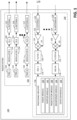
- FIG. 2 illustrated is a functional block diagram that illustrates a transmit side of a PMCW radar on a chip (RoC) 200.
- RoC chip
- the RoC 200 can include a digital portion 202 and an analog portion 204.
- the RoC 200 can include N transmit antennas 224-230, and each transmit antennas can have an associated transmit chain of digital and analog components.
- Each grouping of antennas e.g., 224 and 226, 228 and 230
- the antennas are grouped in pairs, but in other embodiments, different groupings are possible.
- a common seed input 206 can be provided to PRBS generators 208 and 210, which output an identical code sequence which can be modulated by modulators 212 and 214.
- the resulting modulation signal can have a sequence of pulses that are phase shifted on a PRI basis.
- Digital to analog converters 216 and 218 convert the digital signal to an analog signal, and IQ mixers 220 and 222 can apply respective phase shifts ⁇ 0 or ⁇ 1.
- Fig. 3 illustrated is a functional block diagram that illustrates a receive side of a PMCW RoC 300.
- the receive portion includes analog components 304 and digital components 306.
- the receive antennas 302 receives echo signals corresponding to the transmissions from the transmit antennas 224-230.
- the received signals are passed through the Rx Analog processing block 308 and Rx Digital processing block 310, the received signals are sent to a Replay Buffer 312.
- the matched filters needed for Digital Correlation can be generated based on a code sequence from PRBS 316-318 that receive the same seed input that were provided to the transmit antennas (e.g., seed input 206).
- a digital correlator 314 can then perform the correlation and other processing.
- each code sequence provided by the PRBS generators 316-318 can be used to generate two signals for the matched filters, the overall data throughput is halved so the digital correlator performs half the amount of work in a traditional commercial PMCW radar system. With the reduction in bandwidth, the number of range bins can be increased to give longer range on the detection, or the PRI can be reduced so that the radar has a wider Doppler span.
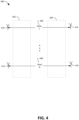
- Fig. 4 illustrated is a functional block diagram 400 that illustrates the transmit sides of a dual PMCW RoC.
- the radar system can have a first RoC 402 and a second RoC 404 that have transmit antennas that are provided common seed inputs.
- transmit antennas 410-412 on RoC 402 and transmit antennas 414-416 on RoC 404 can receive inputs from seeds 406-408.
- the modulation signals for transmit antennas 414 and 410 are identical, but different phase shifts can be applied to each modulation signal by IQ mixers on the respective transmit chains.
- Each RoC 402 and 404 can operate with a single set of parameters which improves robustness and reliability of the radars as each transmitter is cycling through the same parameters on a PRI basis, and not shifting phases between ⁇ 0 or ⁇ 1 as in single RoC embodiment.
- Figs. 7 and 8 illustrate methodologies relating to processing radar data to compute information about an object in a scene. While the methodologies are shown and described as being a series of acts that are performed in a sequence, it is to be understood and appreciated that the methodologies are not limited by the order of the sequence. For example, some acts can occur in a different order than what is described herein. In addition, an act can occur concurrently with another act. Further, in some instances, not all acts may be required to implement a methodology described herein.
- the acts described herein may be computer-executable instructions that can be implemented by one or more processors and/or stored on a computer-readable medium or media.
- the computer-executable instructions can include a routine, a sub-routine, programs, a thread of execution, and/or the like.
- results of acts of the methodologies can be stored in a computer-readable medium, displayed on a display device, and/or the like.
- a range processing step can be carried out that comprises correlating the samples of data received from the receiver digital hardware 310 with a copy of the transmitted digital sequences 316-318 to determine range bins for targets in a scene.
- a velocity FFT is performed with respect to samples of data (slow time) received from the digital correlator 314 to determine (ambiguous) velocity bins for the targets in the scene.
- VLM demultiplexing is performed to construct a multi-dimensional data matrix.
- virtual array formation is performed by extracting arrays from the multi-dimensional matrix that correspond to each transmitter.
- beamforming is performed on each virtual array formed at 708, and at 712, a detector detects targets and filters interfering targets.
- a range processing step is carried out which comprises correlating the samples of data received from the receiver digital hardware 310 with a copy of the transmitted digital sequences 316-318 to determine range bins for targets in a scene.
- a velocity FFT is performed with respect to samples of data (slow time) received from the digital correlator 314 to determine (ambiguous) velocity bins for the targets in the scene.
- non-coherent integration is performed across receivers in the radar system 100, and at 808 a first detection is performed and further demultiplexing is performed in order to compute velocities for the targets.
- beamforming is applied using the detected velocities as well as data corresponding to the detected velocities acquired during the velocity FFT at 804.
- a second detection is performed to assign angular information to the targets (and optionally filtering is undertaken to filter interfering targets).
- Fig. 9 is a schematic of an autonomous vehicle (AV) 900.
- the AV 900 includes the radar system 100.
- the AV 900 includes a computing system 904 that is in communication with the radar system 904, where the computing system 904 is in communication with systems of the AV 900, such as a propulsion system (e.g., an electric motor, a combustion engine, etc.), a braking system, a steering system, etc.
- the AV 900 also optionally includes a camera 906 that is in communication with the computing system 904.
- the AV 900 can also optionally include other sensor systems, such as a LIDAR sensor system, a positional sensor system (such as a GPS sensor system), an accelerometer, etc.
- the computing system 900 receives detections output by the radar system 100 (and optionally images output by the camera 906 and/or other sensor systems) and causes the AV 900 to plan and/or perform a driving maneuver based upon the detections. For instance, the computing system 900 can, based upon the detections, control the propulsion system to cause the AV 900 to accelerate, to maintain a constant velocity, to decelerate, etc. In another example, the computing system 904 can, based upon the detections, control the braking system to initiate braking, to release from braking, etc. In still yet another example, the computing system 904 can, based upon the detections, control the steering system to turn, to maintain course, etc.
- the AV 900 may be a fully autonomous vehicle. In other examples, the radar system 100 can be employed in a partially autonomous vehicle, where detections can be employed by driver assistance technologies.
- the computing device 1000 may be or be included within the radar system 100 and/or the AV 900.
- the computing device 1000 includes at least one processor 1002 that executes instructions that are stored in a memory 1004.
- the instructions may be, for instance, instructions for implementing functionality described as being carried out by one or more systems discussed above or instructions for implementing one or more of the methods described above.
- the processor 1002 may be a GPU, a plurality of GPUs, a CPU, a plurality of CPUs, a multi-core processor, etc.
- the processor 1002 may access the memory 1004 by way of a system bus 1006.
- the memory 1004 may also store range data, velocity data, velocity labels, etc.
- the computing device 1000 additionally includes a data store 1008 that is accessible by the processor 1002 by way of the system bus 1006.
- the data store 1008 may include executable instructions, range data, velocity data, velocity labels, etc.
- the computing device 1000 also includes an input interface 1010 that allows external devices to communicate with the computing device 1000. For instance, the input interface 1010 may be used to receive instructions from an external computer device, etc.
- the computing device 1000 also includes an output interface 1012 that interfaces the computing device 1000 with one or more external devices. For example, the computing device 1000 may transmit control signals to the engine, the braking system, and/or the steering system by way of the output interface 1012.
- the computing device 1000 may be a distributed system. Thus, for instance, several devices may be in communication by way of a network connection and may collectively perform tasks described as being performed by the computing device 1400.
- Computer-readable media includes computer-readable storage media.
- a computer-readable storage media can be any available storage media that can be accessed by a computer.
- such computer-readable storage media can comprise RAM, ROM, EEPROM, CD-ROM or other optical disk storage, magnetic disk storage or other magnetic storage devices, or any other medium that can be used to store desired program code in the form of instructions or data structures and that can be accessed by a computer.
- Disk and disc include compact disc (CD), laser disc, optical disc, digital versatile disc (DVD), floppy disk, and Blu-ray disc (BD), where disks usually reproduce data magnetically and discs usually reproduce data optically with lasers. Further, a propagated signal is not included within the scope of computer-readable storage media.
- Computer-readable media also includes communication media including any medium that facilitates transfer of a computer program from one place to another. A connection, for instance, can be a communication medium.
- the software is transmitted from a website, server, or other remote source using a coaxial cable, fiber optic cable, twisted pair, digital subscriber line (DSL), or wireless technologies such as infrared, radio, and microwave
- coaxial cable, fiber optic cable, twisted pair, DSL, or wireless technologies such as infrared, radio and microwave
- the coaxial cable, fiber optic cable, twisted pair, DSL, or wireless technologies such as infrared, radio and microwave
- the functionality described herein can be performed, at least in part, by one or more hardware logic components.
- illustrative types of hardware logic components include Field-programmable Gate Arrays (FPGAs), Application-specific Integrated Circuits (ASICs), Application-specific Standard Products (ASSPs), System-on-a-chip systems (SOCs), Complex Programmable Logic Devices (CPLDs), etc.
- the disclosure set forth herein relates to a PMCW radar system according to at least the following examples.
Landscapes
- Engineering & Computer Science (AREA)
- Radar, Positioning & Navigation (AREA)
- Remote Sensing (AREA)
- Computer Networks & Wireless Communication (AREA)
- Physics & Mathematics (AREA)
- General Physics & Mathematics (AREA)
- Electromagnetism (AREA)
- Radar Systems Or Details Thereof (AREA)
Priority Applications (2)
| Application Number | Priority Date | Filing Date | Title |
|---|---|---|---|
| EP21209387.6A EP4184196A1 (de) | 2021-11-19 | 2021-11-19 | Phasenmoduliertes dauerstrichradarsystem mit geschwindigkeitsmarkiertem multiplexen zur erzeugung |
| US17/535,562 US12146949B2 (en) | 2021-08-03 | 2021-11-24 | Phase modulated continuous wave radar system that uses velocity labeled multiplexing for generating detections |
Applications Claiming Priority (1)
| Application Number | Priority Date | Filing Date | Title |
|---|---|---|---|
| EP21209387.6A EP4184196A1 (de) | 2021-11-19 | 2021-11-19 | Phasenmoduliertes dauerstrichradarsystem mit geschwindigkeitsmarkiertem multiplexen zur erzeugung |
Publications (1)
| Publication Number | Publication Date |
|---|---|
| EP4184196A1 true EP4184196A1 (de) | 2023-05-24 |
Family
ID=78709357
Family Applications (1)
| Application Number | Title | Priority Date | Filing Date |
|---|---|---|---|
| EP21209387.6A Pending EP4184196A1 (de) | 2021-08-03 | 2021-11-19 | Phasenmoduliertes dauerstrichradarsystem mit geschwindigkeitsmarkiertem multiplexen zur erzeugung |
Country Status (1)
| Country | Link |
|---|---|
| EP (1) | EP4184196A1 (de) |
Citations (2)
| Publication number | Priority date | Publication date | Assignee | Title |
|---|---|---|---|---|
| US9720073B1 (en) * | 2016-04-25 | 2017-08-01 | Uhnder, Inc. | Vehicular radar sensing system utilizing high rate true random number generator |
| US20210190904A1 (en) * | 2019-12-18 | 2021-06-24 | Imec Vzw | Radar Ranging |
-
2021
- 2021-11-19 EP EP21209387.6A patent/EP4184196A1/de active Pending
Patent Citations (2)
| Publication number | Priority date | Publication date | Assignee | Title |
|---|---|---|---|---|
| US9720073B1 (en) * | 2016-04-25 | 2017-08-01 | Uhnder, Inc. | Vehicular radar sensing system utilizing high rate true random number generator |
| US20210190904A1 (en) * | 2019-12-18 | 2021-06-24 | Imec Vzw | Radar Ranging |
Non-Patent Citations (1)
| Title |
|---|
| SUN HONGBO ET AL: "Analysis and comparison of MIMO radar waveforms", 2014 INTERNATIONAL RADAR CONFERENCE, IEEE, 13 October 2014 (2014-10-13), pages 1 - 6, XP032746346, DOI: 10.1109/RADAR.2014.7060251 * |
Similar Documents
| Publication | Publication Date | Title |
|---|---|---|
| US12146949B2 (en) | Phase modulated continuous wave radar system that uses velocity labeled multiplexing for generating detections | |
| EP4130789B1 (de) | Radarsystem mit geschwindigkeitsmarkiertem multiplexen zur erzeugung von detektionen | |
| US11906618B2 (en) | MIMO radar apparatuses and MIMO radar methods | |
| EP4009074B1 (de) | Mimo-radar-verfahren und -system mit co-prime-codierter (cpc) dopplermultiplex-ing (ddm) | |
| CN109917340B (zh) | 一种mimo雷达波形调制解调方法 | |
| US11846696B2 (en) | Reduced complexity FFT-based correlation for automotive radar | |
| US10613195B2 (en) | Radar apparatus and radar method | |
| CN110100188B (zh) | 针对扩展雷达系统的时间和频率同步 | |
| CN111157981A (zh) | 多入多出调频连续波雷达系统 | |
| CN110622026A (zh) | 用于环境检测的方法和装置 | |
| CN118962657A (zh) | 使用二进制移相器的慢时频分复用 | |
| US20240402324A1 (en) | Mimo radar apparatus and mimo radar method | |
| US12578425B2 (en) | MIMO radar apparatus and MIMO radar method | |
| CN104160296A (zh) | 目标检测方法 | |
| US20220050176A1 (en) | Radar device | |
| CN115856866A (zh) | 利用不同脉冲重复频率组的雷达通信 | |
| US20240019565A1 (en) | Motion compensation for fast target detection in automotive radar | |
| EP4538733A1 (de) | Hybrides zufalls-zeitmultiplex-radarsystem und verfahren mit multiple-input-multiple-output (mimo) und doppler-multiplex-verfahren | |
| EP4184196A1 (de) | Phasenmoduliertes dauerstrichradarsystem mit geschwindigkeitsmarkiertem multiplexen zur erzeugung | |
| US12578453B2 (en) | System and method of determining a relative radial velocity of a radar target | |
| US20240353524A1 (en) | Interference mitigation in high resolution radars | |
| EP4732040A1 (de) | System und verfahren zur bestimmung einer relativen radialgeschwindigkeit eines radarziels | |
| US20260063756A1 (en) | Method and apparatus for evaluating radar data from a radar sensor | |
| US12474442B2 (en) | Doppler division multiplexing (DDM) multiple-input multiple-output (MIMO) radar system and decoding method | |
| US20250216540A1 (en) | Mimo radar with object reflected signal overlap detection |
Legal Events
| Date | Code | Title | Description |
|---|---|---|---|
| PUAI | Public reference made under article 153(3) epc to a published international application that has entered the european phase |
Free format text: ORIGINAL CODE: 0009012 |
|
| STAA | Information on the status of an ep patent application or granted ep patent |
Free format text: STATUS: THE APPLICATION HAS BEEN PUBLISHED |
|
| AK | Designated contracting states |
Kind code of ref document: A1 Designated state(s): AL AT BE BG CH CY CZ DE DK EE ES FI FR GB GR HR HU IE IS IT LI LT LU LV MC MK MT NL NO PL PT RO RS SE SI SK SM TR |
|
| P01 | Opt-out of the competence of the unified patent court (upc) registered |
Effective date: 20230526 |
|
| STAA | Information on the status of an ep patent application or granted ep patent |
Free format text: STATUS: REQUEST FOR EXAMINATION WAS MADE |
|
| 17P | Request for examination filed |
Effective date: 20231124 |
|
| RBV | Designated contracting states (corrected) |
Designated state(s): AL AT BE BG CH CY CZ DE DK EE ES FI FR GB GR HR HU IE IS IT LI LT LU LV MC MK MT NL NO PL PT RO RS SE SI SK SM TR |
|
| STAA | Information on the status of an ep patent application or granted ep patent |
Free format text: STATUS: EXAMINATION IS IN PROGRESS |
|
| 17Q | First examination report despatched |
Effective date: 20250814 |