EP4184199A1 - Systèmes, procédés et appareil pour déterminer des caractéristiques d'un radôme - Google Patents
Systèmes, procédés et appareil pour déterminer des caractéristiques d'un radôme Download PDFInfo
- Publication number
- EP4184199A1 EP4184199A1 EP22207694.5A EP22207694A EP4184199A1 EP 4184199 A1 EP4184199 A1 EP 4184199A1 EP 22207694 A EP22207694 A EP 22207694A EP 4184199 A1 EP4184199 A1 EP 4184199A1
- Authority
- EP
- European Patent Office
- Prior art keywords
- radar
- radome
- reflected
- vehicle
- radar signal
- Prior art date
- Legal status (The legal status is an assumption and is not a legal conclusion. Google has not performed a legal analysis and makes no representation as to the accuracy of the status listed.)
- Pending
Links
Images




Classifications
-
- G—PHYSICS
- G06—COMPUTING OR CALCULATING; COUNTING
- G06F—ELECTRIC DIGITAL DATA PROCESSING
- G06F30/00—Computer-aided design [CAD]
- G06F30/20—Design optimisation, verification or simulation
-
- G—PHYSICS
- G01—MEASURING; TESTING
- G01S—RADIO DIRECTION-FINDING; RADIO NAVIGATION; DETERMINING DISTANCE OR VELOCITY BY USE OF RADIO WAVES; LOCATING OR PRESENCE-DETECTING BY USE OF THE REFLECTION OR RERADIATION OF RADIO WAVES; ANALOGOUS ARRANGEMENTS USING OTHER WAVES
- G01S7/00—Details of systems according to groups G01S13/00, G01S15/00, G01S17/00
- G01S7/02—Details of systems according to groups G01S13/00, G01S15/00, G01S17/00 of systems according to group G01S13/00
- G01S7/40—Means for monitoring or calibrating
- G01S7/4004—Means for monitoring or calibrating of parts of a radar system
- G01S7/4039—Means for monitoring or calibrating of parts of a radar system of sensor or antenna obstruction, e.g. dirt- or ice-coating
-
- H—ELECTRICITY
- H01—ELECTRIC ELEMENTS
- H01Q—ANTENNAS, i.e. RADIO AERIALS
- H01Q1/00—Details of, or arrangements associated with, antennas
- H01Q1/42—Housings not intimately mechanically associated with radiating elements, e.g. radome
-
- G—PHYSICS
- G01—MEASURING; TESTING
- G01S—RADIO DIRECTION-FINDING; RADIO NAVIGATION; DETERMINING DISTANCE OR VELOCITY BY USE OF RADIO WAVES; LOCATING OR PRESENCE-DETECTING BY USE OF THE REFLECTION OR RERADIATION OF RADIO WAVES; ANALOGOUS ARRANGEMENTS USING OTHER WAVES
- G01S13/00—Systems using the reflection or reradiation of radio waves, e.g. radar systems; Analogous systems using reflection or reradiation of waves whose nature or wavelength is irrelevant or unspecified
- G01S13/88—Radar or analogous systems specially adapted for specific applications
- G01S13/93—Radar or analogous systems specially adapted for specific applications for anti-collision purposes
- G01S13/931—Radar or analogous systems specially adapted for specific applications for anti-collision purposes of land vehicles
-
- G—PHYSICS
- G01—MEASURING; TESTING
- G01S—RADIO DIRECTION-FINDING; RADIO NAVIGATION; DETERMINING DISTANCE OR VELOCITY BY USE OF RADIO WAVES; LOCATING OR PRESENCE-DETECTING BY USE OF THE REFLECTION OR RERADIATION OF RADIO WAVES; ANALOGOUS ARRANGEMENTS USING OTHER WAVES
- G01S7/00—Details of systems according to groups G01S13/00, G01S15/00, G01S17/00
- G01S7/02—Details of systems according to groups G01S13/00, G01S15/00, G01S17/00 of systems according to group G01S13/00
- G01S7/027—Constructional details of housings, e.g. form, type, material or ruggedness
-
- G—PHYSICS
- G01—MEASURING; TESTING
- G01S—RADIO DIRECTION-FINDING; RADIO NAVIGATION; DETERMINING DISTANCE OR VELOCITY BY USE OF RADIO WAVES; LOCATING OR PRESENCE-DETECTING BY USE OF THE REFLECTION OR RERADIATION OF RADIO WAVES; ANALOGOUS ARRANGEMENTS USING OTHER WAVES
- G01S7/00—Details of systems according to groups G01S13/00, G01S15/00, G01S17/00
- G01S7/02—Details of systems according to groups G01S13/00, G01S15/00, G01S17/00 of systems according to group G01S13/00
- G01S7/40—Means for monitoring or calibrating
- G01S7/4004—Means for monitoring or calibrating of parts of a radar system
- G01S7/4039—Means for monitoring or calibrating of parts of a radar system of sensor or antenna obstruction, e.g. dirt- or ice-coating
- G01S7/4043—Means for monitoring or calibrating of parts of a radar system of sensor or antenna obstruction, e.g. dirt- or ice-coating including means to prevent or remove the obstruction
-
- G—PHYSICS
- G01—MEASURING; TESTING
- G01S—RADIO DIRECTION-FINDING; RADIO NAVIGATION; DETERMINING DISTANCE OR VELOCITY BY USE OF RADIO WAVES; LOCATING OR PRESENCE-DETECTING BY USE OF THE REFLECTION OR RERADIATION OF RADIO WAVES; ANALOGOUS ARRANGEMENTS USING OTHER WAVES
- G01S13/00—Systems using the reflection or reradiation of radio waves, e.g. radar systems; Analogous systems using reflection or reradiation of waves whose nature or wavelength is irrelevant or unspecified
- G01S13/86—Combinations of radar systems with non-radar systems, e.g. sonar, direction finder
-
- G—PHYSICS
- G01—MEASURING; TESTING
- G01S—RADIO DIRECTION-FINDING; RADIO NAVIGATION; DETERMINING DISTANCE OR VELOCITY BY USE OF RADIO WAVES; LOCATING OR PRESENCE-DETECTING BY USE OF THE REFLECTION OR RERADIATION OF RADIO WAVES; ANALOGOUS ARRANGEMENTS USING OTHER WAVES
- G01S13/00—Systems using the reflection or reradiation of radio waves, e.g. radar systems; Analogous systems using reflection or reradiation of waves whose nature or wavelength is irrelevant or unspecified
- G01S13/86—Combinations of radar systems with non-radar systems, e.g. sonar, direction finder
- G01S13/865—Combination of radar systems with lidar systems
-
- G—PHYSICS
- G01—MEASURING; TESTING
- G01S—RADIO DIRECTION-FINDING; RADIO NAVIGATION; DETERMINING DISTANCE OR VELOCITY BY USE OF RADIO WAVES; LOCATING OR PRESENCE-DETECTING BY USE OF THE REFLECTION OR RERADIATION OF RADIO WAVES; ANALOGOUS ARRANGEMENTS USING OTHER WAVES
- G01S13/00—Systems using the reflection or reradiation of radio waves, e.g. radar systems; Analogous systems using reflection or reradiation of waves whose nature or wavelength is irrelevant or unspecified
- G01S13/86—Combinations of radar systems with non-radar systems, e.g. sonar, direction finder
- G01S13/867—Combination of radar systems with cameras
-
- G—PHYSICS
- G01—MEASURING; TESTING
- G01S—RADIO DIRECTION-FINDING; RADIO NAVIGATION; DETERMINING DISTANCE OR VELOCITY BY USE OF RADIO WAVES; LOCATING OR PRESENCE-DETECTING BY USE OF THE REFLECTION OR RERADIATION OF RADIO WAVES; ANALOGOUS ARRANGEMENTS USING OTHER WAVES
- G01S13/00—Systems using the reflection or reradiation of radio waves, e.g. radar systems; Analogous systems using reflection or reradiation of waves whose nature or wavelength is irrelevant or unspecified
- G01S13/88—Radar or analogous systems specially adapted for specific applications
- G01S13/93—Radar or analogous systems specially adapted for specific applications for anti-collision purposes
- G01S13/931—Radar or analogous systems specially adapted for specific applications for anti-collision purposes of land vehicles
- G01S2013/9327—Sensor installation details
- G01S2013/93273—Sensor installation details on the top of the vehicles
-
- H—ELECTRICITY
- H01—ELECTRIC ELEMENTS
- H01Q—ANTENNAS, i.e. RADIO AERIALS
- H01Q1/00—Details of, or arrangements associated with, antennas
- H01Q1/27—Adaptation for use in or on movable bodies
- H01Q1/32—Adaptation for use in or on road or rail vehicles
- H01Q1/325—Adaptation for use in or on road or rail vehicles characterised by the location of the antenna on the vehicle
- H01Q1/3275—Adaptation for use in or on road or rail vehicles characterised by the location of the antenna on the vehicle mounted on a horizontal surface of the vehicle, e.g. on roof, hood, trunk
Definitions
- An autonomous vehicle or autonomously driven vehicle may navigate a path of travel using information about the environment obtained by sensors of the vehicle.
- the autonomous vehicle or ADV may be equipped with various types of sensors in order to detect the environment surrounding the vehicle.
- the autonomous vehicle may include light detection and ranging (lidar) sensors, radio detection and ranging (radar) sensors, sound navigation and ranging (sonar) sensors, image capture devices (e.g., cameras), microphone sensors, and other suitable sensors that scan and record data from the vehicle's surroundings. Sensor data from one or more of these sensors may be used to detect objects and their respective characteristics (position, shape, heading, speed, etc.).
- a radar system or unit may detect objects and estimate the positions of the objects in the environment by transmitting radio signals (i.e., radar signals) and analyzing the returning reflected signals from the objects and other surfaces in the environment.
- Autonomous vehicles may employ one or more radar systems or units for detecting and recognizing objects in the environment surrounding the vehicle.
- the radar system may include a radome (e.g., a radar dome or cover) to protect the internal radar components of the radar system from environmental conditions and objects in the environment.
- the radome may be constructed of one or more materials that permit the transmission and reception of radar signals through the radome.
- environmental elements e.g., rain, hail, snow, road spray, dirt, contaminants, etc.
- a radome When the outer surface of a radome deteriorates or is damaged, material or matter (e.g., rain, snow, moisture, road spray, etc.) may not be effectively repelled and/or dissipated from the radome. As a result, the water shedding capacity or efficacy of the radome may be reduced. For example, water droplets or moisture may accumulate on the radome causing undesired effects on the transmission properties or characteristics of the radome and/or the radar signals that pass through the radome, such as unwanted attenuation, reflection, refraction, absorption, beam deflection, beam broadening, etc.
- material or matter e.g., rain, snow, moisture, road spray, etc.
- the present application discloses embodiments that relate to systems, methods, and apparatus for determining transmission characteristics or properties of a radome (e.g., a radar dome or cover), such as a radome of a radar system or unit.
- the systems, methods, and apparatus may enable a computing device to determine the transmissivity of the radome of a radar system to verify accurate performance and operation of the radar system.
- the computing device may determine the transmission properties or characteristics of the radome to detect undesired accumulation of matter or material (e.g., rain, snow, spray, debris, moisture, etc.) on the radome that may degrade the performance of the radar system.
- An alert or notification may be generated when the condition of the radome has reduced the performance of the radar system to an undesired level.
- the condition of the radome of a vehicle radar system attenuates radar signals that pass through the radome to an unacceptable level
- a technician or a computer device or operator of vehicle may be notified that the performance of the radar system may be potentially degraded and the radome may need to be serviced (e.g., repaired, cleaned, recalibrated, etc.) and/or replaced.
- the reliability of the radar system may be increased and the cost effectiveness of radar operations and maintenance may be improved.
- the present disclosure describes an apparatus for determining a characteristic of a radome.
- the apparatus comprises a memory for storing radar data and a computing device.
- the computing device may be configured to cause a first radar signal to be transmitted toward an object and to receive first radar data representative of a first reflected radar signal.
- the first reflected radar signal may comprise at least a portion of the first radar signal reflected from the object.
- the computing device may also be configured to determine a first parameter associated with the first reflected radar signal based on at least the first radar data and to cause a second radar signal to be transmitted toward the object after a fluid is applied to the radome. Further, the computing device may be configured to receive second radar data representative of a second reflected radar signal.
- the second reflected radar signal may comprise at least a portion of the second radar signal reflected from the object. Additionally, the computing device may be configured to determine a second parameter associated with the second reflected radar signal based on at least the second radar data and compare the first parameter to the second parameter.
- the present disclosure describes a method for determining a characteristic of a radome.
- the method may include causing a first radar signal to be transmitted toward an object and receiving first radar data representative of a first reflected radar signal.
- the first reflected radar signal may comprise at least a portion of the first radar signal reflected from the object.
- the method may also include determining a first parameter associated with the first reflected radar signal based on at least the first radar data and causing a second radar signal to be transmitted toward the object after a fluid is applied to the radome.
- the method may include receiving second radar data representative of a second reflected radar signal.
- the second reflected radar signal may comprise at least a portion of the second radar signal reflected from the object.
- the method may include determining a second parameter associated with the second reflected radar signal based on at least the second radar data and comparing the first parameter to the second parameter.
- the present disclosure describes a non-transitory computer-readable medium configured to store instructions, that when executed by a computing system comprising one or more processors, causes the computing system to perform operations.
- the operations may include causing a first radar signal to be transmitted through a radome toward an object and receiving first radar data representative of a first reflected radar signal.
- the first reflected radar signal may comprise at least a portion of the first radar signal reflected from the object.
- the operations may include determining a first parameter associated with the first reflected radar signal based on at least the first radar data and causing a second radar signal to be transmitted through the radome toward the object after a fluid is applied to the radome. Further, the operations may also include receiving second radar data representative of a second reflected radar signal.
- the second reflected radar signal may comprise at least a portion of the second radar signal reflected from the object. Additionally, the operations may include determining a second parameter associated with the second reflected radar signal based on at least the second radar data and comparing the first parameter to the second parameter.
- a radar system or unit may be used for detecting objects and estimating their positions in the environment by transmitting electromagnetic or radio signals (i.e., radar signals) and analyzing the backscattered or reflected return signals from the objects and other surfaces in an environment.
- the radar system may use one or more antennas to emit (i.e., transmit) radar signals to measure aspects of the environment. For example, the radar system may estimate a range for objects by transmitting short pulses and/or coded waveforms, such as pulsed Doppler radar signals.
- the emitted radar signals may scatter in multiple directions with some penetrating into various surfaces while others reflect off surfaces and back towards one or more receiving antennas of the radar system.
- the radar system may process the reflected radar reflections to generate two dimensional (2D) and/or three dimensional (3D) measurements that represent aspects of the environment, such as the positions, orientations, and movements (including non-movements) of nearby objects and other surfaces located in the surrounding environment.
- 2D two dimensional
- 3D three dimensional
- radar systems or units may be used to measure distances and motions of nearby objects and other surfaces
- radar systems are being increasingly incorporated into vehicles for obtaining and providing useful information for vehicle navigation, obstacle avoidance, and other vehicle operations that may boost overall vehicle safety.
- the radar systems may be used to detect and potentially identify the positions, orientations, and movements (including non-movements) of nearby vehicles, bicycles, pedestrians, animals, and objects surrounding a vehicle.
- the radar systems may also provide information about other features in the vehicle's surrounding environment, such as the location, arrangement, and position of road boundaries, road conditions (e.g., smooth or bumpy surfaces), weather conditions (e.g., wet or snowy roadways), and the relative positions of traffic signs and signals.
- the radar systems may provide a way for vehicle systems to continuously monitor and understand changes during navigation in various environments and may supplement radar sensor data from other types of sensors.
- the radar systems may provide information aimed to assist the vehicle's driver. For instance, radar measurements may be used to generate alerts when the vehicle drifts outside its lane, when the vehicle travels too closely to another vehicle or object, and/or in other ways that can help the driver safely control the vehicle. The radar measurements may also be used to help enable autonomous or semi-autonomous operations by the vehicle. In particular, radar data may be used by control or computer systems to navigate the vehicle's environment.
- a vehicle radar system can include one or more radar systems or units positioned at various locations on a vehicle.
- one or more radar systems may be coupled to the vehicle at various positions, such as side mirrors, bumpers, the roof, front grill, doors, the trunk, or side panels on the vehicle.
- Using exterior locations to attach and position radar systems may enable swift installation of the radar systems on a standard vehicle without requiring redesigning and specially manufacturing the vehicle.
- the orientation and position of the radar systems when the radar systems are coupled at exterior vehicle locations may be easily adjusted. This may also speed up the installation and calibration processes.
- the radar system may be able to capture measurements from optimal positions and orientations on the vehicle.
- the radar system When a radar system is located on the exterior of the vehicle, the radar system may undesirably encounter contact from road debris, which can damage and degrade the performance of the radar system. For instance, as the vehicle navigates a path, debris (e.g., rocks, pieces of road, etc.) may be kicked up and propelled towards the radar system by the vehicle and other nearby vehicles. This debris can damage the radar system and impact subsequent performance of the vehicle radar system overall. In addition, puddles and snow that accumulate on the road can be propelled towards the vehicle by nearby vehicles and similarly degrade the performance over time.
- road debris e.g., rocks, pieces of road, etc.
- This debris can damage the radar system and impact subsequent performance of the vehicle radar system overall.
- puddles and snow that accumulate on the road can be propelled towards the vehicle by nearby vehicles and similarly degrade the performance over time.
- weather conditions can also create conditions that undesirably impact unprotected radar systems coupled at exterior positions on the vehicle.
- Rain, hail, sleet, snow, and other weather conditions may undesirably come into contact with the radome and, over time, degrade the performance and condition of the radar system.
- exposure to weather elements may cause the radar system to degrade and perform less optimally.
- any radar system coupled at an exterior location on a vehicle is also exposed to undesirable contact from pedestrians, such as while the vehicle is parked and not in use.
- the radar system may include a radome or some form of housing or cover composed of a radio-frequency transparent material.
- the radome may be designed to protect and conceal one or more components of the radar system (e.g., antennas) from the environment.
- the radome may enclose or cover the antennas of the radar system and provide protection from undesirable environmental factors, such as debris and weather conditions.
- the radome may be constructed from materials that allow radar signals (e.g., transmitted and received radar signals) to pass therethrough with minimum attenuation (e.g., minimum distortion, reflection, absorption, etc).
- the radome may be formed from one or more plastic materials.
- the outer surface of the radome may be susceptible to the accumulation of matter or material (e.g., rain, snow, dirt, water, etc.). For example, under certain conditions, rain, snow, road spray and/or moisture may accumulate or build up on the outer surface of the radome, and thereby adversely impact the performance of the radar system.
- the outer surface of the radome may be coated with a hydrophobic or super-hydrophobic coating or film. For example, hydrophobic coatings or surfaces may be used to mitigate or reduce the amount of material or matter (e.g., rain, snow, dirt, water, etc.) that may accumulate on the radome.
- the outer surface of the radome may be curved to further facilitate water and/or snow run-off
- the transmission properties or characteristics of the radome e.g., the outer coating or film
- the performance and/or sensitivity of the radar system may be reduced or diminished.
- a damaged or deteriorated outer surface or coating/film of the radome may not effectively disburse and/or repel material or matter (e.g., rain, snow, moisture, water, spray, etc.) from the radome. As such, water droplets or moisture may accumulate, build up, and/or remain on the outer surface of the radome.
- the presence of the water droplets or moisture on the radome may cause undesired effects on the radar signals that pass through the radome (e.g., unwanted attenuation, reflection, refraction, absorption, beam deflection, beam broadening, etc.). These undesired effects may decrease the detection and/or sensing capability of the radar system as well as reduce the accuracy of the radar system's measurements. As a result, the performance of the radar system may be degraded or diminished as signals transmitted and received by the radar unit may suffer from attenuation and other undesired effects caused by the condition of the radome. Therefore, it might not be safe to allow a vehicle operating autonomously to navigate using a radar system having a damaged and/or deteriorated radome.
- Vehicle radar systems or units may routinely undergo manual or offline inspection, testing, and/or verification to maintain proper performance and adherence to radar and/or radome specifications and requirements. For instance, human supervision or cross-sensor validation may be used to detect damage and/or deterioration of a radome of a radar system.
- a conventional vehicle radar verification process may involve skilled technicians operating a radar system to observe specially curated and placed calibration targets in a controlled calibration environment. As such, testing a scanning range of a radar unit may present a challenge due to the physical space needed to test the entire scanning range of the radar unit. Further, conventional radar inspection and verification processes may limit a vehicle's use. Thus, conventional processes may be highly manual, time consuming, and associated with high costs, such as costs for setup and maintenance of a suitable calibration environment.
- example embodiments of the present disclosure describe techniques for monitoring, testing, and evaluating a radome.
- the techniques may measure and determine the transmission characteristics and/or properties of a radome of a vehicle radar system as the vehicle operates in an environment.
- the techniques may use radar data as a basis for monitoring and evaluating the characteristics of the radome.
- a computing device of a radar system or vehicle may periodically (or continuously) monitor the transmissivity and/or condition of the radome and, in turn, the performance of the radar system while avoiding the downtime and costs associated with manual inspections and offline testing and evaluations.
- the techniques described herein may enable the transmission characteristics and/or properties of a radome of a radar system or unit to be periodically evaluated before an undesired level of degradation occurs.
- the transmissibility of the radome may be monitored and evaluated without having to take the radar system or a vehicle out of operation.
- the techniques may also facilitate the continuous or periodic monitoring of the radome in the field without requiring a testing chamber or highly-controlled targets.
- the techniques may use radar data collected during typical operations by the radar system and/or vehicle. That is, the condition of the radome and the performance of the radar system may be determined from radar reflections or returns obtained from the environment. This may eliminate the need to remove a vehicle and its radar system from service and may significantly decrease the downtime of the radar system and/or vehicle.
- the techniques may reduce the time and resources used to monitor and evaluate the transmission characteristics of the radome of a radar system or vehicle.
- the techniques described herein may be performed by systems, methods, and apparatus that determine the transmission characteristics of a radome (e.g., a housing or cover) of a vehicle or a radar system.
- the systems, methods, and apparatus may use one or more computing devices (e.g., processors, field programmable gate arrays (FPGAs), etc.) onboard a vehicle, such as a computing device of a vehicle radar system or unit or a central computing system configured to control one or more systems of the vehicle.
- the one or more computing devices may monitor and evaluate the transmissivity of the radome to ensure accurate performance of the radar system as the vehicle operates in an environment.
- the one or more computing devices may be configured to effectively and accurately monitor and/or evaluate the transmission properties or characteristics of the radome to detect undesired accumulation of matter or material (e.g., rain, snow, water droplets, moisture, etc.) on the radome.
- the one or more computing devices may obtain radar data during multiple time intervals (e.g., radar reflections or returns) and compile the radar data over multiple intervals to assess the condition of the radome and the performance of the radar system.
- one or more remote computing devices may assist with monitoring and evaluating the radome of the radar system and/or vehicle.
- a technician or a computing device or operator of a vehicle may be alerted and/or notified when the transmission characteristics or properties of the radome are reduced or degraded due to matter or material (e.g., water droplets, moisture, spray, etc.) on the radome.
- matter or material e.g., water droplets, moisture, spray, etc.
- water droplets and/or moisture on the radome may increase the reflection, absorption, and/or attenuation of the transmitted and reflected signals.
- the accumulation of the matter or material on the radome causes the transmitted and reflected signals that propagate through the radome to degrade to an undesirable level
- a technician or a computing device or operator of a vehicle may be notified that the condition of the radome and/or the performance of the radar system may be potentially degraded and the radome may need to be serviced (e.g., cleaned, repaired, etc.) and/or replaced.
- the reliability of the radar system may be increased and the cost effectiveness of radar operations and maintenance may be improved.
- a system or apparatus may be configured to determine the transmission characteristics and/or properties of a radome.
- the system may include a fluid source and a radar system.
- the radar system may transmit and receive radar signals and may detect or identify one or more objects or targets at a distance in an environment based on the radar signals. For example, a sign, vehicle, a tree, building, wall, landmark, a portion of a vehicle, and/or another object may be identified as a target.
- the radar system can be configured to determine that the detected object satisfies a set of conditions prior to initializing a process for monitoring and/or evaluating the radome.
- radar data indicative of the detected object may be required to meet one or more conditions, such as that the radar data exceeds a particular signal-to-noise ratio (SNR) threshold and/or exceeds a range threshold.
- SNR signal-to-noise ratio
- the radar system may select portions of the radar data (e.g., peaks) that are each likely to represent a single target or object (e.g., a car, truck, street sign, or another large and/or metallic object) associated with a high radar cross section (RCS) that can make determinations of one or more targets more accurate.
- RCS radar cross section
- the radar system may transmit radar signals toward the object.
- the radar system may transmit the radar signals on a first channel.
- the radar system may receive reflected signals of the transmitted radar signals and determine or measure one or more parameters of the reflected radar signals.
- the one or more parameters may be determined at the beginning of a vehicle mission, before entering wet conditions, and/or after the conclusion of the vehicle mission.
- the one or more parameters may be used as initial or baseline parameters to compare with parameters of subsequent reflected radar signals.
- the radar system may receive reflected radar signals and determine a first parameter associated with a first reflected radar signal. Once the radar system receives the first reflected radar signal, a fluid device may be operated to apply fluid to the radome of the radar system.
- the radar system may transmit radar signals toward the object.
- the radar system may transmit the radar signals on the first channel (e.g., same channel).
- the radar system may receive reflected signals of the transmitted radar signals and determine or measure one or more parameters of the reflected signals.
- the radar system may receive the reflected radar signals and determine a second parameter associated with a second reflected radar signal.
- the system may compare the parameters of the reflected signals. For example, the radar system may compare the initial or baseline parameter of the first reflected radar signal to the parameters of subsequently reflected radar signals received after the fluid has been applied to the radome. In some examples, a first parameter of a first reflected radar signal may be compared to a second parameter of a second reflected radar signal.
- the first and second parameter of the reflected radar signals may each comprise a power characteristic (e.g., a maximum power level, an average power level, a spectral power density, etc.), a radar bandwidth, a radar duration, a signal magnitude, an amplitude, and/or a phase.
- the power level of the first reflected radar signal may be compared to the power level of the second reflected radar signal.
- the comparison of the parameters of the reflected radar signals may be used to determine the transmissivity or condition of the radome of the radar system and to determine whether the radar system is providing accurate radar results.
- the comparison may indicate a loss in transmissivity of the radome (e.g., radome loss) due to damage or deterioration of the radome.
- the damage or deterioration of the radome may cause accumulation of undesired material or matter (e.g., moisture, water droplets, etc.) on the radome reducing the transmissivity of the radome.
- the radar system may determine the differences between the parameters of reflected radar signals based on the comparison.
- the radar system may determine a power difference (e.g., transmission loss) between a power level associated with the first reflected radar signal and a power level associated with the second reflected signal.
- the difference may be used to detect a decrease in the transmissivity of the radome, damage or deterioration of the radome, and/or an accumulation of material or matter (e.g., moisture, water droplets, etc.) on the radome.
- the formation and/or accumulation of water droplets or moisture on the radome of the radar unit may cause the transmissivity of the radome to decrease.
- the radar system may detect material or matter on the radome (e.g., water droplets, moisture, etc.) based on the difference.
- the radar system may compare the difference between the parameters of the reflected radar signals to a threshold value.
- the threshold value may be a reference value associated with the radar/radome specifications and/or system requirements for a particular type of the radome.
- the radar system or a computing device may determine how to respond based on the difference. For example, the formation of precipitation and/or water droplets on the radome of the radar unit may cause the transmissibility of the radome to fall outside the radar and/or radome specifications.
- the computing device may be configured to generate or provide a notification or alert indicating an undesired condition of the radome.
- a threshold value e.g., a reference value of a radar and/or radome specifications, a pre-stored threshold value, etc.
- the computing device may be configured to generate or provide a notification or alert indicating an undesired condition of the radome.
- the radar system may provide an alert to a technician or a computing device or operator of a vehicle to investigate the radar system's performance, such as an alert that indicates that the radar system is performing poorly and/or the radar signals passing through the radome have degraded to an undesired level.
- the computing device may be configured to provide a notification or alert indicating the condition of the radome and/or that the performance of the radar system may be potentially degraded and the radome may need to be repaired or replace.
- the computing device may provide an alert that indicates the radome requires cleaning and/or may initiate an automatic process that helps remove the material on the radome.
- the computing device or a vehicle system may activate a cleaning mechanism (e.g., liquid spray, high-pressure gas tube, wiper, etc.) to attempt to clean the radome.
- the radome may include a heating option, pressurized air blowing device, a fan, and/or a wiper that can be used to help remove the material.
- the alert may indicate that transmissivity or condition of the radome has decreased to an undesirable level.
- the radome may be serviced (e.g., cleaned, removed, replaced, repaired, fixed, recalibrated, etc.) and/or replaced before the radar system and vehicle is put back into operation.
- the reliability of the radar unit may be increased and the cost effectiveness of radar operation and maintenance may be improved.
- an example system may be implemented in or may take the form of a radar system or computer system of an automobile.
- a system may also be implemented in or take the form of other systems for vehicles, such as cars, trucks, motorcycles, buses, boats, airplanes, helicopters, lawn mowers, earth movers, boats, snowmobiles, aircraft, recreational vehicles, amusement park vehicles, farm equipment, construction equipment, trams, golf carts, trains, trolleys, and robot devices.
- vehicles are possible as well.
- Figure 1 is a functional block diagram illustrating systems of an example vehicle 100, which may be configured to operate fully or partially in an autonomous mode. More specifically, the vehicle 100 may operate in an autonomous mode without human interaction through receiving control instructions from a computing system. As part of operating in the autonomous mode, the vehicle 100 may use one or more sensors to detect and possibly identify objects of the surrounding environment to enable safe navigation. In some implementations, the vehicle 100 may also include subsystems that enable a driver to control operations of the vehicle 100.
- the vehicle 100 may include various subsystems, such as a propulsion system 102, a sensor system 104, a control system 106, one or more peripherals 108, a power supply 110, a computer or computing system 112, a data storage 114, and a user interface 116.
- the vehicle 100 may include more or fewer subsystems, which can each include multiple elements.
- the subsystems and components of the vehicle 100 may be interconnected in various ways.
- functions of the vehicle 100 described herein can be divided into additional functional or physical components, or combined into fewer functional or physical components within implementations.
- the control system 106 and computer system 112 may be combined into a single system that operates the vehicle 100 in accordance with various operations.
- the propulsion system 102 may include one or more components operable to provide powered motion for the vehicle 100 and can include an engine/motor 118, an energy source 119, a transmission 120, and wheels/tires 121, among other possible components.
- the engine/motor 118 may be configured to convert the energy source 119 into mechanical energy and may correspond to one or a combination of an internal combustion engine, an electric motor, steam engine, or Stirling engine, among other possible options.
- the propulsion system 102 may include multiple types of engines and/or motors, such as a gasoline engine and an electric motor.
- the energy source 119 represents a source of energy that may, in full or in part, power one or more systems of the vehicle 100 (e.g., an engine/motor 118).
- the energy source 119 can correspond to gasoline, diesel, other petroleum-based fuels, propane, other compressed gas-based fuels, ethanol, solar panels, batteries, and/or other sources of electrical power.
- the energy source 119 may include a combination of fuel tanks, batteries, capacitors, and/or flywheels.
- the transmission 120 may transmit mechanical power from the engine/motor 118 to the wheels/tires 121 and/or other possible systems of the vehicle 100.
- the transmission 120 may include a gearbox, a clutch, a differential, and a drive shaft, among other possible components.
- a drive shaft may include axles that connect to one or more of the wheels/tires 121.
- the wheels/tires 121 of the vehicle 100 may have various configurations within example implementations.
- the vehicle 100 may exist in a unicycle, bicycle/motorcycle, tricycle, or car/truck four-wheel format, among other possible configurations.
- the wheels/tires 121 may connect to the vehicle 100 in various ways and can exist in different materials, such as metal and rubber.
- the sensor system 104 can include various types of sensors or sensor devices, such as a Global Positioning System (GPS) 122, an inertial measurement unit (IMU) 124, a radar unit or system 126, a laser rangefinder/lidar sensor 128, a camera 130, a steering sensor 123, and a throttle/brake sensor 125, among other possible sensors.
- GPS Global Positioning System
- IMU inertial measurement unit
- the sensor system 104 may also include sensors configured to monitor internal systems of the vehicle 100 (e.g., O 2 monitor, fuel gauge, engine oil temperature, brake wear).
- the GPS 122 may include a transceiver operable to provide information regarding the position of vehicle 100 with respect to the Earth.
- the IMU 124 may have a configuration that uses one or more accelerometers and/or gyroscopes and may sense position and orientation changes of vehicle 100 based on inertial acceleration. For example, the IMU 124 may detect a pitch and yaw of the vehicle 100 while the vehicle 100 is stationary or in motion.
- the radar unit 126 may represent one or more systems configured to use radio signals to sense objects, including the speed and heading of the objects, within the local environment of the vehicle 100.
- the radar unit 126 may include antennas configured to transmit and receive radio signals.
- the radar unit 126 may correspond to a mountable radar unit or system configured to obtain measurements of the surrounding environment of the vehicle 100.
- the laser rangefinder/lidar 128 may include one or more laser sources, a laser scanner, and one or more detectors or sensors, among other system components, and may operate in a coherent mode (e.g., using heterodyne detection) or in an incoherent detection mode.
- the one or more detectors or sensor of the laser rangefinder/lidar 128 may include one or more photodetectors.
- the photodetectors may be capable of detecting single photon avalanche diodes (SPAD). Further, such photodetectors can be arranged (e.g., through an electrical connection in series) into an array (e.g., as in a silicon photomultiplier (SiPM)).
- the camera 130 may include one or more devices (e.g., a still camera or video camera) configured to capture images of the environment of the vehicle 100.
- the camera may include an image sensor configured to capture a series of images (e.g., image frames) in a time-sequential manner.
- the image sensor may capture images at a particular rate or at a particular time interval between successive frame exposures.
- the steering sensor 123 may sense a steering angle of the vehicle 100, which may involve measuring an angle of the steering wheel or measuring an electrical signal representative of the angle of the steering wheel. In some implementations, the steering sensor 123 may measure an angle of the wheels of the vehicle 100, such as detecting an angle of the wheels with respect to a forward axis of the vehicle 100. The steering sensor 123 may also be configured to measure a combination (or a subset) of the angle of the steering wheel, electrical signal representing the angle of the steering wheel, and the angle of the wheels of the vehicle 100.
- the throttle/brake sensor 125 may detect the position of either the throttle position or brake position of the vehicle 100. For instance, the throttle/brake sensor 125 may measure the angle of both the gas pedal (throttle) and brake pedal or may measure an electrical signal that could represent, for instance, an angle of a gas pedal (throttle) and/or an angle of a brake pedal. The throttle/brake sensor 125 may also measure an angle of a throttle body of the vehicle 100, which may include part of the physical mechanism that provides modulation of the energy source 119 to the engine/motor 118 (e.g., a butterfly valve or carburetor).
- the throttle/brake sensor 125 may measure a pressure of one or more brake pads on a rotor of the vehicle 100 or a combination (or a subset) of the angle of the gas pedal (throttle) and brake pedal, electrical signal representing the angle of the gas pedal (throttle) and brake pedal, the angle of the throttle body, and the pressure that at least one brake pad is applying to a rotor of the vehicle 100.
- the throttle/brake sensor 125 may be configured to measure a pressure applied to a pedal of the vehicle, such as a throttle or brake pedal.
- the control system 106 may include components configured to assist in navigating the vehicle 100, such as a steering unit 132, a throttle 134, a brake unit 136, a sensor fusion algorithm 138, a computer vision system 140, a navigation/pathing system 142, and an obstacle avoidance system 144. More specifically, the steering unit 132 may be operable to adjust the heading of the vehicle 100, and the throttle 134 may control the operating speed of the engine/motor 118 to control the acceleration of the vehicle 100.
- the brake unit 136 may decelerate vehicle 100, which may involve using friction to decelerate the wheels/tires 121. In some implementations, brake unit 136 may convert kinetic energy of the wheels/tires 121 to electric current for subsequent use by a system or systems of the vehicle 100.
- the sensor fusion algorithm 138 of the control system 106 may include a Kalman filter, Bayesian network, or other algorithms that can process data from the sensor system 104.
- the sensor fusion algorithm 138 may provide assessments based on incoming sensor data, such as evaluations of individual objects and/or features, evaluations of a particular situation, and/or evaluations of potential impacts within a given situation.
- the computer vision system 140 of the control system 106 may include hardware and software operable to process and analyze images in an effort to determine objects, environmental objects (e.g., stop lights, road way boundaries, etc.), and obstacles. As such, the computer vision system 140 may use object recognition, Structure From Motion (SFM), video tracking, and other algorithms used in computer vision, for instance, to recognize objects, map an environment, track objects, estimate the speed of objects, etc.
- SFM Structure From Motion
- the navigation/pathing system 142 of the control system 106 may determine a driving path for the vehicle 100, which may involve dynamically adjusting navigation during operation. As such, the navigation/pathing system 142 may use data from the sensor fusion algorithm 138, the GPS 122, and maps, among other sources to navigate the vehicle 100.
- the obstacle avoidance system 144 may evaluate potential obstacles based on sensor data and cause systems of the vehicle 100 to avoid or otherwise negotiate the potential obstacles.
- the vehicle 100 may also include peripherals 108, such as a wireless communication system 146, a touchscreen 148, a microphone 150, and/or a speaker 152.
- the peripherals 108 may provide controls or other elements for a user to interact with the user interface 116.
- the touchscreen 148 may provide information to users of the vehicle 100.
- the user interface 116 may also accept input from the user via the touchscreen 148.
- the peripherals 108 may also enable the vehicle 100 to communicate with devices, such as other vehicle devices.
- the wireless communication system 146 may wirelessly communicate with one or more devices directly or via a communication network.
- wireless communication system 146 could use 3G cellular communication, such as code-division multiple access (CDMA), evolution-data optimized (EVDO), global system for mobile communications (GSM) / general packet radio service (GPRS), or cellular communication, such as 4G worldwide interoperability for microwave access (WiMAX) or long-term evolution (LTE), or 5G.
- wireless communication system 146 may communicate with a wireless local area network (WLAN) using WIFI@ or other possible connections.
- Wireless communication system 146 may also communicate directly with a device using an infrared link, Bluetooth, or ZigBee, for example.
- Other wireless protocols such as various vehicular communication systems, are possible within the context of the disclosure.
- wireless communication system 146 may include one or more dedicated short-range communications (DSRC) devices that could include public and/or private data communications between vehicles and/or roadside stations.
- DSRC dedicated short-range communications
- the vehicle 100 may include the power supply 110 for powering components.
- the power supply 110 may include a rechargeable lithium-ion or lead-acid battery in some implementations.
- the power supply 110 may include one or more batteries configured to provide electrical power.
- the vehicle 100 may also use other types of power supplies.
- the power supply 110 and the energy source 119 may be integrated into a single energy source.
- the vehicle 100 may also include the computer system 112 to perform operations, such as operations described therein.
- the computer system 112 may include at least one processor 113 (which could include at least one microprocessor) operable to execute instructions 115 stored in a non-transitory computer readable medium, such as the data storage 114.
- the computer system 112 may represent a plurality of computing devices that may serve to control individual components or subsystems of the vehicle 100 in a distributed fashion.
- the data storage 114 may contain instructions 115 (e.g., program logic) executable by the processor 113 to execute various functions of the vehicle 100, including those described above in connection with Figure 1 .
- the data storage 114 may contain additional instructions as well, including instructions to transmit data to, receive data from, interact with, and/or control one or more of the propulsion system 102, the sensor system 104, the control system 106, and the peripherals 108.
- the data storage 114 may store data such as roadway maps, path information, among other information. Such information may be used by the vehicle 100 and the computer system 112 during the operation of the vehicle 100 in the autonomous, semi-autonomous, and/or manual modes.
- the vehicle 100 may include the user interface 116 for providing information to or receiving input from a user of the vehicle 100.
- the user interface 116 may control or enable control of content and/or the layout of interactive images that could be displayed on the touchscreen 148. Further, the user interface 116 could include one or more input/output devices within the set of peripherals 108, such as the wireless communication system 146, the touchscreen 148, the microphone 150, and the speaker 152.
- the computer system 112 may control the function of the vehicle 100 based on inputs received from various subsystems (e.g., the propulsion system 102, the sensor system 104, and the control system 106), as well as from the user interface 116.
- the computer system 112 may utilize input from the sensor system 104 in order to estimate the output produced by the propulsion system 102 and the control system 106.
- the computer system 112 could be operable to monitor many aspects of the vehicle 100 and its subsystems.
- the computer system 112 may disable some or all functions of the vehicle 100 based on signals received from the sensor system 104.
- the components of the vehicle 100 could be configured to work in an interconnected fashion with other components within or outside their respective systems.
- the camera 130 could capture a plurality of images that could represent information about a state of an environment of the vehicle 100 operating in an autonomous mode.
- the state of the environment could include parameters of the road on which the vehicle is operating.
- the computer vision system 140 may be able to recognize the slope (grade) or other features based on the plurality of images of a roadway.
- the combination of the GPS 122 and the features recognized by the computer vision system 140 may be used with map data stored in the data storage 114 to determine specific road parameters.
- the radar unit 126 may also provide information about the surroundings of the vehicle.
- a combination of various sensors which could be termed input-indication and output-indication sensors
- the computer system 112 could interact to provide an indication of an input provided to control a vehicle or an indication of the surroundings of a vehicle.
- the computer system 112 may make a determination about various objects based on data that is provided by systems other than the radio system.
- the vehicle 100 may have lasers or other optical sensors configured to sense objects in a field of view of the sensors (e.g., vehicle).
- the computer system 112 may use the outputs from the various sensors to determine information about objects in a field of view of the vehicle, and may determine distance and direction information to the various objects.
- the computer system 112 may also determine whether objects are desirable or undesirable based on the outputs from the various sensors.
- Figure 1 shows various components of the vehicle 100, i.e., the wireless communication system 146, the computer system 112, the data storage 114, and the user interface 116, as being integrated into the vehicle 100, one or more of these components could be mounted or associated separately from the vehicle 100.
- the data storage 114 could, in part or in full, exist separate from the vehicle 100.
- the vehicle 100 could be provided in the form of device elements that may be located separately or together.
- the device elements that make up the vehicle 100 could be communicatively coupled together in a wired and/or wireless fashion.
- Figure 2 depicts an example physical configuration of the vehicle 200, which may represent one possible physical configuration of vehicle 100 described in reference to Figure 1 .
- the vehicle 200 may include the sensor unit 202, the wireless communication system 204, the radio unit 206, the deflectors 208, and the camera 210, among other possible components.
- the vehicle 200 may include some or all of the elements of components described in Figure 1 .
- the vehicle 200 is depicted in Figure 2 as a car, the vehicle 200 can have other configurations within examples, such as a truck, a van, a semitrailer truck, a motorcycle, a golf cart, an off-road vehicle, or a farm vehicle, among other possible examples.
- the sensor unit 202 may include one or more sensors configured to capture information of the surrounding environment of the vehicle 200.
- the sensor unit 202 may include any combination of cameras, radars, LIDARs, range finders, radio devices (e.g., Bluetooth and/or 802.11), and acoustic sensors, among other possible types of sensors.
- the sensor unit 202 may include one or more movable mounts operable to adjust the orientation of sensors in the sensor unit 202.
- the movable mount may include a rotating platform that can scan sensors so as to obtain information from each direction around the vehicle 200.
- the movable mount of the sensor unit 202 may also be movable in a scanning fashion within a particular range of angles and/or azimuths.
- the sensor unit 202 may include mechanical structures that enable the sensor unit 202 to be mounted atop the roof of a car. Additionally, other mounting locations are possible within examples.
- the wireless communication system 204 may have a location relative to the vehicle 200 as depicted in Figure 2 , but can also have different locations within implementations.
- the wireless communication system 200 may include one or more wireless transmitters and one or more receivers that may communicate with other external or internal devices.
- the wireless communication system 204 may include one or more transceivers for communicating with a user's device, other vehicles, and roadway elements (e.g., signs, traffic signals), among other possible entities.
- the vehicle 200 may include one or more vehicular communication systems for facilitating communications, such as dedicated short-range communications (DSRC), radio frequency identification (RFID), and other proposed communication standards directed towards intelligent transport systems.
- DSRC dedicated short-range communications
- RFID radio frequency identification
- the camera 210 may have various positions relative to the vehicle 200, such as a location on a front windshield of vehicle 200. As such, the camera 210 may capture images of the environment of the vehicle 200. As illustrated in Figure 2 , the camera 210 may capture images from a forward-looking view with respect to the vehicle 200, but other mounting locations (including movable mounts) and viewing angles of the camera 210 are possible within implementations. In some examples, the camera 210 may correspond to one or more visible light cameras. Alternatively or additionally, the camera 210 may include infrared sensing capabilities. The camera 210 may also include optics that may provide an adjustable field of view.
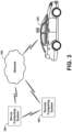
- FIG. 3 is a conceptual illustration of wireless communication between various computing systems related to an autonomous vehicle, according to an example implementation.
- wireless communication may occur between a remote computing system 302 and the vehicle 200 via a network 304.
- Wireless communication may also occur between a server computing system 306 and the remote computing system 302, and between the server computing system 306 and the vehicle 200.
- the vehicle 200 can correspond to various types of vehicles capable of transporting passengers or objects between locations and may take the form of any one or more of the vehicles discussed above.
- the vehicle 200 may operate in an autonomous mode that enables a control system to safely navigate the vehicle 200 between destinations using sensor measurements.
- the vehicle 200 may navigate with or without passengers. As a result, the vehicle 200 may pick up and drop off passengers between desired destinations.
- the remote computing system 302 may represent any type of device related to remote assistance techniques, including but not limited to those described herein.
- the remote computing system 302 may represent any type of device configured to (i) receive information related to the vehicle 200, (ii) provide an interface through which a human operator can in turn perceive the information and input a response related to the information, and (iii) transmit the response to vehicle 200 or to other devices.
- the remote computing system 302 may take various forms, such as a workstation, a desktop computer, a laptop, a tablet, a mobile phone (e.g., a smart phone), and/or a server.
- the remote computing system 302 may include multiple computing devices operating together in a network configuration.
- the remote computing system 302 may include one or more subsystems and components similar or identical to the subsystems and components of vehicle 200. At a minimum, the remote computing system 302 may include a processor configured for performing various operations described herein. In some implementations, the remote computing system 302 may also include a user interface that includes input/output devices, such as a touchscreen and a speaker. Other examples are possible as well.
- the network 304 represents infrastructure that enables wireless communication between the remote computing system 302 and the vehicle 200.
- the network 304 also enables wireless communication between the server computing system 306 and the remote computing system 302, and between the server computing system 306 and the vehicle 200.
- the position of the remote computing system 302 can vary within examples.
- the remote computing system 302 may have a remote position from the vehicle 200 that has wireless communication via the network 304.
- the remote computing system 302 may correspond to a computing device within the vehicle 200 that is separate from the vehicle 200, but with which a human operator can interact while a passenger or driver of the vehicle 200.
- the remote computing system 302 may be a computing device with a touchscreen operable by the passenger of the vehicle 200.
- operations described herein that are performed by the remote computing system 302 may be additionally or alternatively performed by the vehicle 200 (i.e., by any system(s) or subsystem(s) of the vehicle 200).
- the vehicle 200 may be configured to provide a remote assistance mechanism with which a driver or passenger of the vehicle can interact.
- the server computing system 306 may be configured to wirelessly communicate with the remote computing system 302 and the vehicle 200 via the network 304 (or perhaps directly with the remote computing system 302 and/or the vehicle 200).
- the server computing system 306 may represent any computing device configured to receive, store, determine, and/or send information relating to the vehicle 200 and the remote assistance thereof.
- the server computing system 306 may be configured to perform any operation(s), or portions of such operation(s), that is/are described herein as performed by the remote computing system 302 and/or the vehicle 200.
- Some implementations of wireless communication related to remote assistance may utilize the server computing system 306, while others may not.
- the server computing system 306 may include one or more subsystems and components similar or identical to the subsystems and components of the remote computing system 302 and/or the vehicle 200, such as a processor configured for performing various operations described herein, and a wireless communication interface for receiving information from, and providing information to, the remote computing system 302 and the vehicle 200.
- a computing or sensor system e.g., the remote computing system 302, the server computing system 306, or a computing system local to the vehicle 200
- at least one computing device or system will be able to analyze the sensor information and possibly control the autonomous vehicle.
- a vehicle may receive data representing objects in an environment in which the vehicle operates (also referred to herein as "environment data") in a variety of ways.
- a sensor or computing system on the vehicle may provide the environment data representing objects of the environment.
- the vehicle may have various sensors, including a camera, a radar sensor, a laser range finder/lidar sensor, an image sensor, a microphone, and other sensors.
- Each of these sensors may communicate data to a computing device (e.g., a processor) in the vehicle about information each respective sensor receives.
- the computing device e.g., a controller or processor
- the processing system may combine data from a lidar sensor or a radar sensor and an image sensor to determine if another vehicle or pedestrian is in front of the autonomous vehicle.
- other combinations of sensor data may be used by the computing system to make determinations about the environment.
- the vehicle While operating in an autonomous mode, the vehicle may control its operation with little-to-no human input. For example, a human-operator may enter an address into the vehicle and the vehicle may then be able to drive, without further input from the human (e.g., the human does not have to steer or touch the brake/gas pedals), to the specified destination.
- the sensor system may be receiving environment data.
- the computing or processing system of the vehicle may alter the control of the vehicle based on the environment data received from the various sensors.
- the vehicle may alter a velocity of the vehicle in response to environment data from the various sensors.
- the vehicle may change velocity in order to avoid obstacles, obey traffic laws, etc.
- a processing system in the vehicle identifies objects near the vehicle, the vehicle may be able to change velocity, or alter the movement in another way.
- the vehicle can request a human operator (or a more powerful computer) to perform one or more remote assistance tasks, such as (i) confirm whether the object is in fact present in the environment (e.g., if there is actually a stop sign or if there is actually no stop sign present), (ii) confirm whether the vehicle's identification of the object is correct, (iii) correct the identification if the identification was incorrect and/or (iv) provide a supplemental instruction (or modify a present instruction) for the autonomous vehicle.
- a human operator or a more powerful computer
- Remote assistance tasks may also include the human operator providing an instruction to control operation of the vehicle (e.g., instruct the vehicle to stop at a stop sign if the human operator determines that the object is a stop sign), although in some scenarios, the vehicle itself may control its own operation based on the human operator's feedback related to the identification of the object.
- the human operator providing an instruction to control operation of the vehicle (e.g., instruct the vehicle to stop at a stop sign if the human operator determines that the object is a stop sign), although in some scenarios, the vehicle itself may control its own operation based on the human operator's feedback related to the identification of the object.
- the vehicle may analyze the environment data representing objects of the environment to determine at least one object having a detection confidence below a threshold.
- a computing device or processor in the vehicle may be configured to detect various objects of the environment based on environment data from various sensors.
- the computing device may be configured to detect objects that may be important for the vehicle to recognize.
- objects may include pedestrians, street signs, other vehicles, indicator signals on other vehicles, and other various objects detected in the captured environment data.
- the detection confidence may be indicative of a likelihood that the determined object is correctly identified in the environment, or is present in the environment.
- the processor may perform object detection of objects within image data in the received environment data, and determine that the at least one object has the detection confidence below the threshold based on being unable to identify the object with a detection confidence above the threshold. If a result of an object detection or object recognition of the object is inconclusive, then the detection confidence may be low or below the set threshold.
- the vehicle may detect objects of the environment in various ways depending on the source of the environment data.
- the environment data may be received from a camera and include image or video data.
- the environment data may be received from a lidar sensor.
- the vehicle may analyze the captured image or video data to identify objects in the image or video data.
- the methods and apparatuses may be configured to monitor image and/or video data for the presence of objects of the environment.
- the environment data may be radar, audio, or other data.
- the vehicle may be configured to identify objects of the environment based on the radar, audio, or other data.
- the techniques the vehicle uses to detect objects may be based on a set of known data. For example, data related to environmental objects may be stored to a memory located in the vehicle. The vehicle may compare received data to the stored data to determine objects. In other implementations, the vehicle may be configured to determine objects based on the context of the data. For example, street signs related to construction may generally have an orange color. Accordingly, the vehicle may be configured to detect objects that are orange, and located near the side of roadways as construction-related street signs. Additionally, when the processing system of the vehicle detects objects in the captured data, it also may calculate a confidence for each object.
- the vehicle may also have a confidence threshold.
- the confidence threshold may vary depending on the type of object being detected. For example, the confidence threshold may be lower for an object that may require a quick responsive action from the vehicle, such as brake lights on another vehicle. However, in other implementations, the confidence threshold may be the same for all detected objects. When the confidence associated with a detected object is greater than the confidence threshold, the vehicle may assume the object was correctly recognized and responsively adjust the control of the vehicle based on that assumption.
- the actions that the vehicle takes may vary. In some implementations, the vehicle may react as if the detected object is present despite the low confidence level. In other implementations, the vehicle may react as if the detected object is not present.
- the vehicle When the vehicle detects an object of the environment, it may also calculate a confidence associated with the specific detected object.
- the confidence may be calculated in various ways depending on the implementation. In one example, when detecting objects of the environment, the vehicle may compare environment data to predetermined data relating to known objects. The closer the match between the environment data to the predetermined data, the higher the confidence. In other implementations, the vehicle may use mathematical analysis of the environment data to determine the confidence associated with the objects.
- the vehicle may transmit, to the remote computing system, a request for remote assistance with the identification of the object.
- the remote computing system may take various forms.
- the remote computing system may be a computing device within the vehicle that is separate from the vehicle, but with which a human operator can interact while a passenger or driver of the vehicle, such as a touchscreen interface for displaying remote assistance information.
- the remote computing system may be a remote computer terminal or other device that is located at a location that is not near the vehicle.
- the request for remote assistance may include the environment data that includes the object, such as image data, audio data, etc.
- the vehicle may transmit the environment data to the remote computing system over a network (e.g., network 304), and in some implementations, via a server (e.g., server computing system 306).
- the human operator of the remote computing system may in turn use the environment data as a basis for responding to the request.
- the object when the object is detected as having a confidence below the confidence threshold, the object may be given a preliminary identification, and the vehicle may be configured to adjust the operation of the vehicle in response to the preliminary identification.
- Such an adjustment of operation may take the form of stopping the vehicle, switching the vehicle to a human-controlled mode, changing a velocity of the vehicle (e.g., a speed and/or direction), among other possible adjustments.
- the vehicle may operate in accordance with the detected object (e.g., come to a stop if the object is identified with high confidence as a stop sign), but may be configured to request remote assistance at the same time as (or at a later time from) when the vehicle operates in accordance with the detected object.
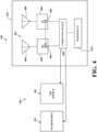
- FIG. 4 is a simplified block diagram depicting components of an example system 400 for monitoring and evaluating a radome.
- An autonomous vehicle may include one or more one of the systems 400.
- the vehicle may include a system (e.g., system 400) mounted to a top of the vehicle and another system may be located at the front of the vehicle.
- the various systems may be located in various different positions throughout the vehicle.
- the system 400 may include a fluid source 410, an air source or blower (e.g., an air puffer system) 420, and a radar system 430.
- the radar system 430 may correspond to the radar system or unit 126 of Figure 1 .
- the radar system 430 may be operated to repeatedly (e.g., periodically) scan the environmental surroundings and generate radar data 432 (e.g., position data). In this way, the radar system 430 may be used to dynamically estimate positions of reflective features in the environment.
- the radar data 432 may be used by a control system of an autonomous vehicle to make navigational decisions (e.g., the autonomous vehicle 100, 200 discussed above in connection with FIGS. 1-2 ). For example, the radar data 432 may be refreshed at a frequency that is sufficient to provide information useful for real time navigation and/or obstacle avoidance for an autonomous vehicle.
- the radar system 430 includes a radome or cover 434 and internal radar components 436.
- the radome 434 may have any suitable shape and may be configured to house one or more of the internal radar components 436 of the radar system 430.
- the radome 434 may be a dome-shaped cover.
- the radome 434 may be comprised of any suitable materials such as plastic, glass, polycarbonate, polystyrene, acrylic, polyester, etc. to allow radar signals to pass therethrough.
- the radome 434 may be formed from a light filtering material that is at least partially transparent to wavelengths of radar signals.
- the outer surface of the radome 434 may be coated with a hydrophobic or super-hydrophobic coating or film.
- the outer surface of the radome may have a hydrophobic or super-hydrophobic coating or film to mitigate or reduce the amount of material or matter (e.g., rain, snow, dirt, water, etc.) that may accumulate on the radome 434.
- the outer surface of the radome may be curved to further facilitate water and/or snow run-off Other configurations of the radome 434 are possible as well.
- the internal radar components 436 of the radar system 430 may be positioned within the radome 434 and may transmit and receive one or more radar signals through the radome 434.
- the internal radar components 436 may include a receiver 438 configured to receive signals from a receiving antenna 440 and a transmitter 442 configured to emit signals from a transmitting antenna 446.
- the receiver 438 and transmitter 442 may each be connected to a computing device 450, which provides commands and control instructions to both the transmitter 442 and the receiver 438.
- the computing device 450 may send instructions to the transmitter 442 to cause radar signals to be emitted from the transmitting antenna 446.
- the transmitter 442 may include local oscillators, mixers, amplifiers and the like to create driving signals to operate to the transmitting antenna 446 in accordance with the instructions from the computing device 450.
- the transmitting antenna 446 may receive the driving signals from the transmitter 442 and emit radar signals or waves.
- the emitted signals from the transmitting antenna 446 may be reflected back by surfaces in the environment and detected by the receiving antenna 440. For example, upon coming into contact with objects or surfaces in the environment, the emitted radar signals may scatter in multiple directions with some penetrating into various surfaces while others reflect off objects or surfaces and back towards the receiving antenna 440 of the radar system 430.
- the reflected signals received at the receiving antenna 440 may be provided to the receiver 438.
- the receiver 438 may condition the signals for further processing by the computing device 450.
- the receiver 438 may include one or more mixers, filters, amplifiers, samplers, down converters, analog to digital converters, and the like to generate digital data or an output.
- the digital data may be provided to the computing device 450 based on the reflected signals received at the receiving antenna 440.
- a signal can be conveyed from a local oscillator 452 included in the transmitter 442 to the receiver 438.
- the conveyed signals can be a copy of the transmitted radiation or signals.
- the receiver 438 may include a mixer 454 to mix the signals from the local oscillator 452 (i.e., a copy of the transmitted signal) with the reflected signal or radiation received via the receiving antenna 440.
- the output of the mixer 454 may then indicate the relative frequency shift of the reflected signals or radiation, such as due to Doppler Effect frequency shifts in the reflected signals.
- the local oscillator 452 may thereby be used as reference signals to compare with the received reflected signals and thereby sensitize the radar system 430 to the reflected signals from objects in motion relative to the radar system 430.
- the local oscillator signals sent back to the mixer 454 in the receiver 438 may then be used as reference signals to compensate for time-variant frequency patterns.
- one or both of the antennas 440, 446 may be directional antennas that are scanned across a scanning zone. For example, one or both of the antennas 440, 446 may be scanned across a scanning zone with an azimuthal span. Information indicative of the orientations of one or both antennas may then be used to determine the direction toward any reflective features that are detected. Thus, a map of reflective features surrounding the radar system 430 may be constructed by combining the range information (based on time of frequency offset of the emitted and received signals) and the direction information (according to orientations of the transmitting and/or receiving antennas 440, 446).
- the computing device 450 of the system 400 may process the received reflected radar signals to generate the radar data 432.
- the radar data 432 may include two dimensional (2D) and/or three dimensional (3D) measurements that represent aspects of the environment, such as the positions, orientations, and movements (including non-movements) of nearby objects and other surfaces located in the surrounding environment. Further, the radar data 432 may indicate the estimated locations of the reflective features.
- the radar data 432 may be output by the computing device 410.
- the computing device 450 of the system 400 may monitor and evaluate the transmissivity of the radome 434 of the radar system 430 to ensure accurate and reliable performance of the radar system 430.
- the computing device 450 may be configured to effectively and accurately monitor and/or evaluate the transmission properties or characteristics of the radome 434 to detect the accumulation of matter or material (e.g., water droplets, precipitation, etc.) on the radome 434.
- the computing device 450 may receive the radar data 432 during multiple time intervals (e.g., radar returns) and compile the radar data 432 over multiple intervals to assess the performance of the radar system.
- one or more remote computing devices or vehicle computing devices can assist with the monitoring and evaluating the radar system 430.
- the computing device 450 of the system 400 may include one or more electronic components and/or elements arranged to facilitate certain operations of the system 400.
- the computing device 450 may comprise one or more general-purpose processors, one or more special-purpose processors, servos, and/or other types of computing devices or controllers.
- the computing device 450 may include circuitry wired to perform one or more of the operations described herein.
- the computing device 450 may include one or more pulse circuits that provide pulse timing signals for triggering emission of pulses or other signals by the transmitter 442.
- the computing device 450 may also include memory or data storage (not shown) to store program instructions executable by the computing device 450 to cause the system 400 to perform the various operations described herein.
- the data storage may be optionally integrated in whole or in part with the computing device 450.
- the data storage may comprise one or more volatile and/or one or more non-volatile storage components, such as optical, magnetic, and/or organic storage.
- the computing device 450 may communicate with an external computing device, controller or the like so as to help facilitate transfer of control signals and/or data between the external computing device and the various components of system 400.
- the computing device 450 of the system 400 may analyze the radar data provided by the receiver 438 to estimate ranges of the radio-reflective features responsible for the reflected radar signals detected by the receiving antenna 440.
- the computing device 450 may, for example, determine the time delay between the emission of radiation or signals from the transmitting antenna 446 and the reception of corresponding reflected radiation or signals at the receiving antenna 440. The determined time delay may then be used to determine the distance to the radio-reflective features based on the measured time-of-flight.
- the radar system 430 may be operated in a frequency modulated continuous wave (FMCW) mode where the transmitter 440 causes the transmitting antenna 446 to emit a signal with a time-changing frequency.
- FMCW frequency modulated continuous wave
- the emitted signal may have a frequency that changes in time in accordance with a frequency saw tooth pattern, for example.
- the frequency difference between the received reflected signals and the emitted signal may be mapped to a corresponding time delay between emission and reception.
- the computing device 450 may receive radar data during the operation of the vehicle and may be configured to determine or identify one or more objects or targets in the environment based on the radar data. For example, a sign, vehicle, a tree, building, wall, landmark, a portion of a vehicle, and/or another object may be identified as a target. In some examples, the computing device 450 may determine a static object (e.g., a tree, street sign, light pole, a part of the vehicle etc.) as a target within the field of view of the radar system. Once the object or target is identified, its radar reflections may be determined based on the received radar signals.
- a static object e.g., a tree, street sign, light pole, a part of the vehicle etc.
- the computing device 450 can be configured to determine that the detected object satisfies a set of conditions.
- the radar data indicative of the detected target or object e.g., a set of peaks of the radar data
- the radar data may be required to meet one or more conditions, such as that the radar data exceeds a particular signal-to-noise ratio (SNR) threshold and/or satisfies a range threshold (e.g., a minimum or maximum distance of the target).
- SNR signal-to-noise ratio
- the computing device 450 may select portions of the radar data (e.g., peaks) that are each likely to represent a single target object (e.g., a vehicle or a portion thereof, street sign, or another large and/or metallic object) associated with a high radar cross section (RCS) that may make the determination of one or more targets more accurate.
- portions of the radar data e.g., peaks
- RCS radar cross section
- the computing device 450 may cause radar signals to be transmitted toward the object.
- the computing device 450 may receive data representative of the reflected radar signals of the transmitted radar signals and determine or measure one or more parameters of the reflected radar signals.
- the computing device may determine parameters for each of a plurality of reflected radar signals.
- the one or more parameters may be determined at the beginning of a vehicle mission, before entering wet conditions, and/or after the conclusion of the vehicle mission.
- the computing device 450 may determine a first or baseline parameter associated with a first reflected radar signal of a transmitted radar signal at the beginning of the mission.
- the computing device 450 may determine an average of the parameters associated with a plurality of reflected radar signals.
- the computing device 450 may determine the parameters associated with a plurality of reflected radar signals for a new radome prior to any deterioration or damage to the outer surface of the radome.
- the computing device 450 may cause a fluid to be applied to the radome 434 of the radar system 430.
- a fluid source may be operated to apply a fluid to the radome 434 as further described below.
- the computing device 450 may cause radar signals to be transmitted toward the object.
- the radar signals may be transmitted after a predetermined time and have substantial the same or different intervals between the transmitted signals.
- the computing device 450 may receive data representative of the reflected signals of the transmitted radar signals at particular times and determine or measure one or more parameters of the reflected signals.
- the computing device 450 may determine a second parameter associated with a second reflected radar signal of the transmitted radar signals.
- the computing device 450 may determine an average of parameters associated with a plurality or series of the reflected radar signals.
- the computing device 450 may compare one or more of the baseline parameters associated with the reflected radar signals to the one or more parameters of the subsequent reflected signals received after applying the fluid.
- the comparison may be used to determine the transmissivity of the radome of the radar system 430 and to determine whether the radar system 430 is providing accurate radar results. For example, when the transmission characteristics of the radome of the radar system fail to satisfy or exceed a threshold level (e.g., a power or loss threshold) based on the parameters of the reflected radar signals, the radar system or a computing device may determine how to respond based on the difference.
- a threshold level e.g., a power or loss threshold
- a first parameter of a first reflected radar signal may be compared to a second parameter of a second reflected radar signal.
- the parameters of the first and second reflected radar signals may each comprise a power characteristic (e.g., a maximum power level, an average power level, a spectral power density, etc.), a radar bandwidth, a radar duration, a signal magnitude, an amplitude, and/or a phase.
- a power level of the first reflected radar signal may be compared to a power level of the second reflected radar signal.
- the computing device 450 may compare one or more of the parameters (or an average of the parameters) associated with a plurality of first reflected radar signals received prior to an application of fluid with an average of the parameters associated with a plurality of reflected radar signals received after the application of the fluid to the radome. In other examples, the computing device 450 may compare a parameter associated with a reflected radar signal to each of a series of the parameters associated with a plurality of reflected radar signals received after the application of the fluid to the radome. As such, the computing device 450 may determine a shedding rate of the radome (e.g., how fast the water clears off the outer surface of the radome).
- the computing device 450 may determine the difference between reflected radar signals (e.g., a power or loss threshold). The difference may be compared to a threshold value, such as a predetermined specification level or limit for a type of radome. In some cases, the comparison may indicate damage or deterioration of the transmissivity of the radome due to material or matter (e.g., moisture, water droplets, etc.) accumulating on the radome
- the computing device 454 may be configured to provide a notification or an alert to a technician or a computing device or operator of a vehicle to investigate the radar system's performance, such as an alert that indicates that the radar signals passing through the radome 434 have degraded to an undesired level, the transmissivity or condition of the radome has been degraded, the performance of the radar system may be potentially degraded, and/or the radome the radar system is
- the vehicle systems may provide an alert that indicates the radome requires cleaning and/or may initiate an automatic process that helps remove the material on the radome.
- the computing device or the system may activate a cleaning mechanism (e.g., liquid spray, high-pressure gas tube, wiper, etc.) to attempt to clean the radome.
- the system may include a heating option, pressurized air blowing device, a fan, and/or a wiper that can be used to help remove the material.
- the computing device may include that the radome may need to be replaced, repaired, and/or fixed. As such, the radome may be serviced (e.g., cleaned, replaced, repaired, fixed, etc.) and/or replaced before the radar system and vehicle is put back into operation.
- the reliability of the radar unit may be increased and the cost effectiveness of radar operation and maintenance may be improved.
- the fluid source or apparatus 410 of the system 400 may be configured to apply a fluid or liquid to the radome 434 of the radar system 430.
- the fluid source 410 may include a sprayer configured to apply or spray fluid on the radome 434.
- the fluid source 410 may also be used to facilitate cleaning the radome or components of the radar system 430.
- the fluid can be applied to the radome to attempt to dissolve or remove material or matter (e.g., water droplets, moisture, dirt, etc.) disposed on a surface of the radome 434.
- a wiper e.g., similar to a windshield wiper
- Other examples are possible.
- the air source (e.g., air puffer device) 420 of the system 400 may be configured to facilitate the drying and/or cleaning of the radome 434 of the radar system 430.
- the air source 420 may include a fan or blower and/or a heater.
- the air source 420 may include a high-pressure pump configured to apply air or gas onto the surface of the radome 434 to dry the radome 434. For instance, air or a gas may be applied to attempt to dissolve or remove material and/or matter (e.g., water droplets, dirt, dust, etc.) accumulated on a surface of the radome 434.
- system 400 can be alternatively implemented with fewer or more components than those shown.
- Figure 5 is a flowchart of example method 500 for operating a system, according to one or more embodiments.
- the method 500 may include one or more operations, functions, or actions, as depicted by one or more of blocks 502-516, each of which may be carried out by any of the apparatus, systems, or devices shown in prior figures, among other possible systems.
- each block of the flowchart may represent a module, a segment, or a portion of program code, which includes one or more instructions executable by one or more processors for implementing specific logical functions or steps in the process.
- the program code may be stored on any type of computer readable medium, for example, such as a storage device including a disk or hard drive.
- each block may represent circuitry that is wired to perform the specific logical functions in the process.
- Alternative implementations are included within the scope of the example implementations of the present application in which functions may be executed out of order from that shown or discussed, including substantially concurrent or in reverse order, depending on the functionality involved, as would be understood by those reasonably skilled in the art.
- the method 500 may be performed in whole or in part by a computing device, such as a device similar to or the same as computing device 450 described above.
- the computing device may be part of a radar system or be located onboard a vehicle, such as a central computing device.
- one or more operations of the method 500 can be performed by a computing device that is remote from and wirelessly coupled to the vehicle (e.g., remote computing device 304 or server 306).
- a server can perform each of the blocks 502-516, and adjust the operations of the radar system by sending instructions to a central control system of the vehicle that, upon receipt, causes the central control system to control a vehicle radar system to adjust its operation.
- some examples involve using multiple computing devices, such as a combination of computing devices and FPGAs associated with the radar system.
- a system may include a radar system or unit configured to receive radar signals that are reflected back to the radar system by one or more surfaces in an environment.
- the system may transmit radar signals that may reflect off various objects within the surrounding environment and be subsequently received by an antenna of the radar system.
- the antenna may include at least one receiving antenna that receives signals or electromagnetic energy from the environment for subsequent processing.
- the at least one receiving antenna may correspond to a first reception channel that may be a physical channel of a radar unit.
- the physical channel may be a single antenna or single antenna array of the radar system.
- the at least one receiving antenna may include one or more uniform linear arrays (ULAs). Other types of antennas may also be used.
- the system may estimate positions of objects in the environment by analyzing the backscattered or reflected return signals from the objects and other surfaces in the environment.
- the system may process the received radar reflections to generate two dimensional (2D) and/or three dimensional (3D) measurements that represent aspects of the environment, such as the positions, orientations, and movements (including non-movements) of nearby objects and other surfaces located in the surrounding environment.
- the system may estimate a range for an object by transmitting short pulses and/or coded waveforms, such as pulsed Doppler radar signals.
- the system may include one or more computing devices to determine or identify an object or target in the environment based on the radar data. For example, a sign, vehicle, a tree, building, wall, landmark, a portion of a vehicle, and/or another object may be identified as the target based on the radar data.
- a FPGA or another device may filter the radar data to ensure that the detection corresponds to an object in the vehicle's environment.
- the system may identify a static object (e.g., a tree, street sign, light pole, a part of the vehicle etc.) as a target within the field of view of the radar system. Once the object or target is identified, its radar reflections may be determined based on the received radar signals.
- the computing device may select portions of the radar data (e.g., peaks) that are each likely to represent a single target object (e.g., a car, truck, street sign, or another large and/or metallic object) associated with a high radar cross section (RCS) that can make determinations of objects or targets more accurate.
- peaks portions of the radar data that are each likely to represent a single target object (e.g., a car, truck, street sign, or another large and/or metallic object) associated with a high radar cross section (RCS) that can make determinations of objects or targets more accurate.
- RCS radar cross section
- the computing device can be configured to determine that the detected object satisfies a set of conditions prior to performing an evaluation of a radome.
- the radar data indicative of the detected object e.g., a set of peaks of the radar data
- the radar data may be required to meet one or more conditions, such as that the radar data exceeds a particular signal-to-noise ratio (SNR) threshold and/or satisfies or is within a range threshold.
- SNR signal-to-noise ratio
- the set of conditions may be used to filter out object detections that are less useful to determine the condition of the radome.
- the set of conditions can be adjustable and predefined in some examples.
- the set of conditions may include one or more conditions that depend on the current environment of the vehicle.
- the method 500 may include causing a first radar signal to be transmitted toward an object.
- the radar system may transmit one or more initial radar signals toward the object.
- the radar system may transmit the radar signals at a frequency over a first channel of a plurality of channels of the radar system.
- the system may include a radome that provides protection for the components of the system.
- the system may transmit the radar signals through the radome towards the object in the environment and may receive one or more reflected radar signals through the radome.
- the method 500 involves receiving first radar data representative of a first reflected radar signal that comprises at least a portion of the first radar signal reflected from the object.
- the transmitted radar signal may reflect off the object or target in the environment and may be subsequently received by the at least one receiving antenna.
- the at least one receiving antenna of the system may be configured to receive radar signals that are reflected back to the system by one or more objects or targets in an environment.
- the first reflected radar signal may comprise at least a portion of the transmitted radar signal reflected from the object.
- the first reflected signal may be transformed into first radar data representative of the first reflected radar signal.
- the system may receive radar data representative of the first reflected radar signal comprising at least a portion of the first radar signal reflected from the object.
- the method 500 may involve determining a first parameter associated with the first reflected radar signal based on at least the first radar data.
- the system may determine or measure one or more parameters of the reflected radar signals.
- the system receives a first reflected radar signal and determines a first parameter associated with the first reflected radar signal.
- the parameter associated with the first reflected signals may comprise a power characteristic (e.g., a maximum power level, an average power level, a spectral power density, etc.), radar bandwidth, radar duration, a signal magnitude, an amplitude, or a phase.
- the system may determine a power level associated with the first reflected radar signal.
- the method 500 may involve causing a second radar signal to be transmitted toward the object after a fluid is applied to the radome of the system.
- the system may transmit radar signals on the same channel as the initial radar signals.
- the same or substantially similar signal should be received by the at least one receiving antenna and the reflected radar signals for the channel should be substantially identical, except for effects caused by radome.
- the system may be able to determine the transmissibility of the radome based on the differences in these two reflection signals as further described below.
- the system may cause a fluid or liquid to be applied to the radome.
- a fluid device may be operated to apply fluid or liquid to the radome.
- the system may transmit radar signals toward the object.
- the transmission of the radar signals may be performed at the same frequency and/or on the same channel that transmitted the initial radar signals at block 504.
- block 510 of method 500 may be performed after a predetermined period of time once the fluid is applied to the radome of the radar system.
- the predetermined period of time may be short, on the order of 10s of milliseconds.
- block 510 may be performed immediately after applying the fluid (e.g., within milliseconds or seconds).
- the method may involve receiving second radar data representative of a second reflected radar signal comprising at least a portion of the second radar signal reflected from the object.
- the transmitted radar signals may reflect off the object or target within the surrounding environment and may be subsequently received by the at least one receiving antenna.
- the at least one receiving antenna of the system may be configured to receive radar signals that are reflected back to the system by the object or target in an environment.
- the system may receive a second reflected radar signal.
- the second reflected radar signal may comprise at least a portion of a radar signal reflected from the object or object.
- the second reflected signal may be transformed into second radar data representative of the second reflected radar signal.
- the system may receive second radar data representative of a second reflected radar signal comprising at least a portion of the second radar signal reflected from the object.
- the method may include determining a second parameter associated with the second reflected radar signal based on at least the second reflected radar data.
- the system may determine or measure one or more parameters of the reflected radar signals.
- the system receives a second reflected radar signal and determines a second parameter associated with the second reflected radar signal.
- the parameter of the second reflected radar signal may comprise a power characteristic (e.g., a maximum power level, an average power level, a power spectrum, etc.), radar bandwidth, radar duration, a signal magnitude, an amplitude, and/or a phase.
- the system may determine a power level associated with a second reflected radar signal.
- the method may involve comparing the first parameter to the second parameter.
- the system may be able to determine the condition or transmissivity of the radome by comparing the reflected radar signals. After determining the parameters associated with each of the reflected radar signals, the system may compare the parameters of the reflected signals. For example, the system may compare the initial or baseline parameter of the first reflected radar signal to one or more parameters of subsequently reflected radar signals received after the fluid has been applied to the radome. In some examples, a first parameter of a first reflected radar signal may be compared to a second parameter of a second reflected radar signal.
- the first and second parameter of the reflected radar signals may each comprise a power characteristic (e.g., a maximum power level, an average power level, etc.), a radar bandwidth, a radar duration, a signal magnitude, an amplitude, and/or a phase.
- a power characteristic e.g., a maximum power level, an average power level, etc.
- the power level of the first reflected radar signal may be compared to the power level of the second reflected radar signal.
- the system may compare the initial power level of the first reflected radar signal to power levels of a series of subsequently reflected radar signals received after the fluid has been applied to the radome.
- the comparison of the parameters of the reflected radar signals may be used to determine the transmissivity or condition of the radome of the radar system and to determine whether the radar system is providing accurate radar results.
- the comparison may indicate a loss in transmissivity of the radome (e.g., radome loss) due to damage or deterioration of the radome.
- the damage or deterioration of the radome may cause accumulation of undesired material or matter (e.g., moisture, water droplets, etc.) on the radome reducing the transmissivity of the radome.
- the radar system may determine the differences between the parameters of reflected radar signals based on the comparison.
- the radar system may determine a power difference (e.g., transmission loss) between a power level associated with the first reflected radar signal and a power level associated with the second reflected signal.
- the difference may be used to detect a decrease in the transmissivity of the radome, damage or deterioration of the radome, and/or an accumulation of material or matter (e.g., moisture, water droplets, etc.) on the radome.
- the formation and/or accumulation of water droplets or moisture on the radome of the radar unit may cause the transmissivity of the radome to decrease.
- the radar system may detect material or matter on the radome (e.g., water droplets, moisture, etc.) based on the difference.
- the radar system may compare the difference between the parameters of the reflected radar signals to a threshold value.
- the threshold value may be a reference value associated with the radar/radome specifications and/or system requirements for a particular type of the radome.
- the radar system or a computing device may determine how to respond based on the difference. For example, the formation of precipitation and/or water droplets on the radome of the radar unit may cause the transmissibility of the radome to fall outside the radar and/or radome specifications.
- the computing device may be configured to generate or provide a notification or alert indicating an undesired condition of the radome.
- a threshold value e.g., a reference value of a radar and/or radome specifications, a pre-stored threshold value, etc.
- the computing device may be configured to generate or provide a notification or alert indicating an undesired condition of the radome.
- the radar system may provide an alert to a technician or a computing device or operator of a vehicle to investigate the radar system's performance, such as an alert that indicates that the radar system is performing poorly and/or the radar signals passing through the radome have degraded to an undesired level.
- the computing device may be configured to provide a notification or alert indicating the condition of the radome and/or that the performance of the radar system may be potentially degraded and the radome may need to be repaired or replace.
- the computing device may provide an alert that indicates the radome requires cleaning and/or may initiate an automatic process that helps remove the material on the radome.
- the computing device or a vehicle system may activate a cleaning mechanism (e.g., liquid spray, high-pressure gas tube, wiper, etc.) to attempt to clean the radome.
- the radome may include a heating option, pressurized air blowing device, a fan, and/or a wiper that can be used to help remove the material.
- the alert may indicate that transmissivity or condition of the radome has decreased to an undesirable level.
- the radome may be serviced (e.g., cleaned, removed, replaced, repaired, fixed, recalibrated, etc.) and/or replaced before the radar system and vehicle is put back into operation.
- the reliability of the radar unit may be increased and the cost effectiveness of radar operation and maintenance may be improved.
- Blocks 502-516 may be repeated based on various criteria to monitor and evaluate the transmissivity or condition of the radome of the system.
- Figure 6 is a schematic diagram of a computer program, according to an example implementation.
- the disclosed methods may be implemented as computer program instructions encoded on a non-transitory computer-readable storage media in a machine-readable format, or on other non-transitory media or articles of manufacture.
- computer program product 600 is provided using signal bearing medium 902, which may include one or more programming instructions 604 that, when executed by one or more processors may provide functionality or portions of the functionality described above with respect to Figures 1 -7.
- the signal bearing medium 602 may encompass a non-transitory computer-readable medium 606, such as, but not limited to, a hard disk drive, a CD, a DVD, a digital tape, memory, components to store remotely (e.g., on the cloud), etc.
- the signal bearing medium 602 may encompass a communication medium (e.g., a fiber optic cable, a waveguide, a wired communications link, a computer recordable medium 608, such as, but not limited to, memory, read/write (R/W) CDs, R/W DVDs, etc.
- the signal bearing medium 602 may encompass a communications medium 610, such as, but not limited to, a digital and/or an analog wireless communication link, etc.).
- the signal bearing medium 602 may correspond to a remote storage (e.g., a cloud).
- a computing system may share information with the cloud, including sending or receiving information.
- the computing system may receive additional information from the cloud to augment information obtained from sensors or another entity.
- the signal bearing medium 602 may be conveyed by a wireless form of the communications medium 610.
- the one or more programming instructions 604 may be, for example, computer executable and/or logic implemented instructions.
- a computing device such as the computer system 112 of Figure 1 or remote computing system 302 and perhaps server computing systems of Figures 3 may be configured to provide various operations, functions, or actions in response to the programming instructions 604 conveyed to the computer system 112 by one or more of the computer readable medium 606, the computer recordable medium 608, and/or the communications medium 610.
- the non-transitory computer readable medium could also be distributed among multiple data storage elements and/or cloud (e.g., remotely), which could be remotely located from each other.
- the computing device that executes some or all of the stored instructions could be a vehicle, such as vehicle 200 illustrated in Figure 2 .
- the computing device that executes some or all of the stored instructions could be another computing device, such as a server.
Landscapes
- Engineering & Computer Science (AREA)
- Remote Sensing (AREA)
- Radar, Positioning & Navigation (AREA)
- Physics & Mathematics (AREA)
- General Physics & Mathematics (AREA)
- Computer Networks & Wireless Communication (AREA)
- Electromagnetism (AREA)
- Theoretical Computer Science (AREA)
- Computer Hardware Design (AREA)
- Evolutionary Computation (AREA)
- Geometry (AREA)
- General Engineering & Computer Science (AREA)
- Radar Systems Or Details Thereof (AREA)
Applications Claiming Priority (1)
| Application Number | Priority Date | Filing Date | Title |
|---|---|---|---|
| US17/530,108 US12362470B1 (en) | 2021-11-18 | 2021-11-18 | Systems, methods, and apparatus for determining characteristics of a radome |
Publications (1)
| Publication Number | Publication Date |
|---|---|
| EP4184199A1 true EP4184199A1 (fr) | 2023-05-24 |
Family
ID=84359090
Family Applications (1)
| Application Number | Title | Priority Date | Filing Date |
|---|---|---|---|
| EP22207694.5A Pending EP4184199A1 (fr) | 2021-11-18 | 2022-11-16 | Systèmes, procédés et appareil pour déterminer des caractéristiques d'un radôme |
Country Status (3)
| Country | Link |
|---|---|
| US (1) | US12362470B1 (fr) |
| EP (1) | EP4184199A1 (fr) |
| CN (1) | CN116136935A (fr) |
Cited By (1)
| Publication number | Priority date | Publication date | Assignee | Title |
|---|---|---|---|---|
| WO2026010533A1 (fr) * | 2024-07-01 | 2026-01-08 | Telefonaktiebolaget Lm Ericsson (Publ) | Détermination de l'état de revêtement d'un radôme |
Families Citing this family (1)
| Publication number | Priority date | Publication date | Assignee | Title |
|---|---|---|---|---|
| CN119001628A (zh) * | 2023-05-16 | 2024-11-22 | 本田技研工业株式会社 | 车辆外部检测装置 |
Citations (3)
| Publication number | Priority date | Publication date | Assignee | Title |
|---|---|---|---|---|
| JPH10282229A (ja) * | 1997-04-03 | 1998-10-23 | Honda Motor Co Ltd | Fmレーダ装置 |
| US20070040727A1 (en) * | 2005-08-16 | 2007-02-22 | Mitsubishi Denki Kabushiki Kaisha | Radar device |
| US20200200868A1 (en) * | 2017-03-30 | 2020-06-25 | Geopraevent Ag | Radar System Having a Clearing Device |
Family Cites Families (27)
| Publication number | Priority date | Publication date | Assignee | Title |
|---|---|---|---|---|
| JP3244792B2 (ja) | 1992-08-04 | 2002-01-07 | 富士通株式会社 | 自己動作不良検知機能付自動車衝突防止レーダ |
| US5398035A (en) * | 1992-11-30 | 1995-03-14 | The United States Of America As Represented By The Administrator Of The National Aeronautics And Space Administration | Satellite-tracking millimeter-wave reflector antenna system for mobile satellite-tracking |
| US5371505A (en) | 1993-04-22 | 1994-12-06 | Microwave Power Devices, Inc. | Radome test systems and methods |
| DE19847688C2 (de) | 1998-10-15 | 2000-10-26 | Hilti Ag | Verfahren und Anwendung desselben in einem elektromagnetischen Sensor zur Entdeckung von Fremdkörpern in einem Medium mittels Radar |
| JP3308231B2 (ja) | 1999-05-17 | 2002-07-29 | 本田技研工業株式会社 | レーダ装置 |
| US6469659B1 (en) * | 2001-05-03 | 2002-10-22 | Delphi Technologies, Inc. | Apparatus and method for detecting radar obstruction |
| DE10209927B4 (de) * | 2002-03-07 | 2004-04-29 | Daimlerchrysler Ag | Leistungsüberwachung für Radarsysteme |
| JP3915742B2 (ja) | 2003-06-20 | 2007-05-16 | 株式会社デンソー | 車両用物体認識装置 |
| JP2005156337A (ja) | 2003-11-26 | 2005-06-16 | Hitachi Ltd | 車載用レーダ装置 |
| JP2005291808A (ja) | 2004-03-31 | 2005-10-20 | Fujitsu Ltd | 車載レーダ装置 |
| DE102006054320A1 (de) | 2006-11-17 | 2008-05-21 | Robert Bosch Gmbh | Verfahren und Vorrichtung zum Erkennen von Niederschlag mittels Radar |
| JP4629686B2 (ja) | 2007-01-19 | 2011-02-09 | 三菱電機株式会社 | 車載制御システム |
| JP2009250640A (ja) | 2008-04-01 | 2009-10-29 | Toyota Motor Corp | 車載用レーダ装置、及びレーダ汚れ報知方法 |
| DE102009001231A1 (de) * | 2009-02-27 | 2010-09-02 | Robert Bosch Gmbh | FMCW-Radarortungsgerät mit Einrichtung zur Detektion eines Radombelages |
| US8685544B2 (en) * | 2009-03-23 | 2014-04-01 | The Boeing Company | Durable UV blocking transparent coating |
| JP5059904B2 (ja) | 2010-05-12 | 2012-10-31 | 三菱電機株式会社 | 車載レーダ装置 |
| DE102010029699A1 (de) | 2010-06-04 | 2011-12-22 | Robert Bosch Gmbh | Radarsensor und Verfahren zur Detektion von Niederschlag mit einem Radarsensor |
| US9799949B2 (en) | 2014-09-30 | 2017-10-24 | Nidec Corporation | On-vehicle radar device and vehicle |
| US10817065B1 (en) | 2015-10-06 | 2020-10-27 | Google Llc | Gesture recognition using multiple antenna |
| EP3258288B1 (fr) | 2016-06-14 | 2024-07-31 | Rohde & Schwarz GmbH & Co. KG | Procédé pour tester les propriétés de réflexion et de transmission d'un corps de radôme automobile, ainsi qu'un appareil permettant de tester la transmission et des propriétés de réflexion d'un corps de radôme d'automobile |
| EP3290946B1 (fr) | 2016-09-02 | 2019-08-14 | Preco Electronics, LLC | Appareil de surveillance et d'alerte pour performances de radôme affectées par des salissures ou des débris |
| EP3460506B1 (fr) | 2017-09-25 | 2026-01-21 | Aptiv Technologies AG | Procédé de surveillance de la plage de performance d'un système radar automobile |
| EP3486996B1 (fr) * | 2017-11-20 | 2021-09-01 | Progress Rail Inspection & Information Systems S.r.l. | Radôme dotè d' un mécanisme à essuyage |
| US11327153B2 (en) | 2019-10-01 | 2022-05-10 | Waymo Llc | Motion compensation in radar system for autonomous vehicle |
| JP2021090128A (ja) * | 2019-12-03 | 2021-06-10 | 日本電気株式会社 | 無線通信システム |
| KR102952015B1 (ko) | 2020-02-18 | 2026-04-13 | 현대모비스 주식회사 | 차량용 레이더 센서 |
| EP4353547A4 (fr) * | 2021-07-07 | 2024-06-26 | Huawei Technologies Co., Ltd. | Procédé de détection de capteur, appareil de détection de capteur et véhicule |
-
2021
- 2021-11-18 US US17/530,108 patent/US12362470B1/en active Active
-
2022
- 2022-11-16 EP EP22207694.5A patent/EP4184199A1/fr active Pending
- 2022-11-18 CN CN202211448408.6A patent/CN116136935A/zh active Pending
Patent Citations (3)
| Publication number | Priority date | Publication date | Assignee | Title |
|---|---|---|---|---|
| JPH10282229A (ja) * | 1997-04-03 | 1998-10-23 | Honda Motor Co Ltd | Fmレーダ装置 |
| US20070040727A1 (en) * | 2005-08-16 | 2007-02-22 | Mitsubishi Denki Kabushiki Kaisha | Radar device |
| US20200200868A1 (en) * | 2017-03-30 | 2020-06-25 | Geopraevent Ag | Radar System Having a Clearing Device |
Cited By (1)
| Publication number | Priority date | Publication date | Assignee | Title |
|---|---|---|---|---|
| WO2026010533A1 (fr) * | 2024-07-01 | 2026-01-08 | Telefonaktiebolaget Lm Ericsson (Publ) | Détermination de l'état de revêtement d'un radôme |
Also Published As
| Publication number | Publication date |
|---|---|
| CN116136935A (zh) | 2023-05-19 |
| US12362470B1 (en) | 2025-07-15 |
Similar Documents
| Publication | Publication Date | Title |
|---|---|---|
| US12093052B2 (en) | Wide-view LIDAR with areas of special attention | |
| US12439003B2 (en) | Real-time adjustment of vehicle sensor field of view volume | |
| US12275430B2 (en) | Identification of proxy calibration targets for a fleet of vehicles | |
| US9086481B1 (en) | Methods and systems for estimating vehicle speed | |
| US9043072B1 (en) | Methods and systems for correcting an estimated heading using a map | |
| CN115366886B (zh) | 使用雷达检测不利道路状况的方法和系统 | |
| US12344201B2 (en) | Wiper devices for sensor housings | |
| EP4184199A1 (fr) | Systèmes, procédés et appareil pour déterminer des caractéristiques d'un radôme | |
| US12501003B2 (en) | Multi-sensor assembly with improved backward view of a vehicle | |
| US20260004405A1 (en) | Methods and Systems for Mitigating the Effects of Weather-related Attenuation on Radar Imagery | |
| EP4339700A1 (fr) | Ouvertures remplaçables, chauffées et pouvant être séchées pour systèmes optiques | |
| US20260129148A1 (en) | Real-Time Adjustment Of Vehicle Sensor Field Of View Volume | |
| HK40108187A (en) | Wiper devices for sensor housings | |
| HK40107909A (en) | Replaceable, heated, and wipeable apertures for optical systems |
Legal Events
| Date | Code | Title | Description |
|---|---|---|---|
| PUAI | Public reference made under article 153(3) epc to a published international application that has entered the european phase |
Free format text: ORIGINAL CODE: 0009012 |
|
| STAA | Information on the status of an ep patent application or granted ep patent |
Free format text: STATUS: THE APPLICATION HAS BEEN PUBLISHED |
|
| AK | Designated contracting states |
Kind code of ref document: A1 Designated state(s): AL AT BE BG CH CY CZ DE DK EE ES FI FR GB GR HR HU IE IS IT LI LT LU LV MC ME MK MT NL NO PL PT RO RS SE SI SK SM TR |
|
| STAA | Information on the status of an ep patent application or granted ep patent |
Free format text: STATUS: REQUEST FOR EXAMINATION WAS MADE |
|
| 17P | Request for examination filed |
Effective date: 20231108 |
|
| RBV | Designated contracting states (corrected) |
Designated state(s): AL AT BE BG CH CY CZ DE DK EE ES FI FR GB GR HR HU IE IS IT LI LT LU LV MC ME MK MT NL NO PL PT RO RS SE SI SK SM TR |
|
| STAA | Information on the status of an ep patent application or granted ep patent |
Free format text: STATUS: EXAMINATION IS IN PROGRESS |
|
| 17Q | First examination report despatched |
Effective date: 20250113 |
|
| GRAP | Despatch of communication of intention to grant a patent |
Free format text: ORIGINAL CODE: EPIDOSNIGR1 |
|
| STAA | Information on the status of an ep patent application or granted ep patent |
Free format text: STATUS: GRANT OF PATENT IS INTENDED |
|
| RIC1 | Information provided on ipc code assigned before grant |
Ipc: G01S 7/40 20060101AFI20260126BHEP Ipc: G01S 7/02 20060101ALI20260126BHEP Ipc: G01S 13/86 20060101ALI20260126BHEP Ipc: G01S 13/931 20200101ALN20260126BHEP |
|
| RIC1 | Information provided on ipc code assigned before grant |
Ipc: G01S 7/40 20060101AFI20260202BHEP Ipc: G01S 7/02 20060101ALI20260202BHEP Ipc: G01S 13/86 20060101ALI20260202BHEP Ipc: G01S 13/931 20200101ALN20260202BHEP |
|
| INTG | Intention to grant announced |
Effective date: 20260226 |