EP4185159B1 - Berührungsloser spender für fliessfähige nahrungsmittel - Google Patents
Berührungsloser spender für fliessfähige nahrungsmittel Download PDFInfo
- Publication number
- EP4185159B1 EP4185159B1 EP21720365.2A EP21720365A EP4185159B1 EP 4185159 B1 EP4185159 B1 EP 4185159B1 EP 21720365 A EP21720365 A EP 21720365A EP 4185159 B1 EP4185159 B1 EP 4185159B1
- Authority
- EP
- European Patent Office
- Prior art keywords
- food product
- pump
- main body
- automated
- product dispenser
- Prior art date
- Legal status (The legal status is an assumption and is not a legal conclusion. Google has not performed a legal analysis and makes no representation as to the accuracy of the status listed.)
- Active
Links
Images





Classifications
-
- B—PERFORMING OPERATIONS; TRANSPORTING
- B67—OPENING, CLOSING OR CLEANING BOTTLES, JARS OR SIMILAR CONTAINERS; LIQUID HANDLING
- B67D—DISPENSING, DELIVERING OR TRANSFERRING LIQUIDS, NOT OTHERWISE PROVIDED FOR
- B67D1/00—Apparatus or devices for dispensing beverages on draught
- B67D1/08—Details
- B67D1/0888—Means comprising electronic circuitry (e.g. control panels, switching or controlling means)
-
- A—HUMAN NECESSITIES
- A47—FURNITURE; DOMESTIC ARTICLES OR APPLIANCES; COFFEE MILLS; SPICE MILLS; SUCTION CLEANERS IN GENERAL
- A47G—HOUSEHOLD OR TABLE EQUIPMENT
- A47G19/00—Table service
- A47G19/12—Vessels or pots for table use
- A47G19/18—Containers for delivering jam, mustard, or the like
- A47G19/183—Containers for delivering jam, mustard, or the like by applying external pressure, i.e. by pumping or squeezing
-
- B—PERFORMING OPERATIONS; TRANSPORTING
- B67—OPENING, CLOSING OR CLEANING BOTTLES, JARS OR SIMILAR CONTAINERS; LIQUID HANDLING
- B67D—DISPENSING, DELIVERING OR TRANSFERRING LIQUIDS, NOT OTHERWISE PROVIDED FOR
- B67D1/00—Apparatus or devices for dispensing beverages on draught
- B67D1/08—Details
- B67D1/10—Pump mechanism
-
- B—PERFORMING OPERATIONS; TRANSPORTING
- B67—OPENING, CLOSING OR CLEANING BOTTLES, JARS OR SIMILAR CONTAINERS; LIQUID HANDLING
- B67D—DISPENSING, DELIVERING OR TRANSFERRING LIQUIDS, NOT OTHERWISE PROVIDED FOR
- B67D1/00—Apparatus or devices for dispensing beverages on draught
- B67D1/08—Details
- B67D1/12—Flow or pressure control devices or systems, e.g. valves, gas pressure control, level control in storage containers
- B67D1/1202—Flow control, e.g. for controlling total amount or mixture ratio of liquids to be dispensed
Definitions
- the present disclosure generally relates to the automatic dispensing of a flowable food product, such as condiments, from a storage container or pouch. More specifically, the present disclosure relates to a sanitary, touch-free automatic flowable food product dispensing apparatus and method to use such apparatus.
- Flowable food products can include a wide variety of products, such as condiments (i.e. ketchup, mustard, mayonnaise, tartar sauce, etc.), syrups, dressings, cheeses, fudge, caramel or other similar food products that can flow and thus be pumped.
- condiments i.e. ketchup, mustard, mayonnaise, tartar sauce, etc.
- syrups syrups
- dressings cheeses
- fudge caramel or other similar food products that can flow and thus be pumped.
- a manual pump typically include a flexible diaphragm pump mounted to a main body that includes an open interior sized to receive a supply of the food product to be dispensed.
- These dispensers typically rely upon the manual action of a handle or lever that must be depressed by the user to depress and release a flexible diaphragm of the diaphragm pump.
- the pump handle collects bacteria or viruses since multiple users touch the same pump handle during daily usage.
- the pump handle is not sanitized during use in a single day and is sanitized only at the end of a day or the beginning of the next day. For this reason, the pump handle provides a point for possible contamination from the multiple users.
- the present disclosure utilizes a flexible diaphragm pump in combination with an automated pump actuator to eliminate the need for a manual pump handle.
- the present disclosure relates to a touch-free flowable food product dispenser according to claim 1.
- the touch-free food product dispenser includes a sensor that detects the presence of the hand of a user above a sensing area.
- an automated pump actuation unit operates a pump assembly to dispense a volume of food product from the food product dispenser.
- the automated pump actuation unit is designed to be removable from the main body of the dispenser as a single unit, which allows for the conversion of mechanical food product dispensers that include a manual actuation handle to touch-free dispensers.
- the flowable food product dispenser of the present disclosure is designed to be operable to selectively dispense a food product as desired by a user.
- the dispenser includes a main body that has an open interior sized to receive a supply of food product to be dispensed.
- the main body receives and supports a pump assembly.
- the pump assembly is a flexible diaphragm pump that is securely mounted to the main body.
- the pump assembly includes a first end in fluid communication with the supply of flowable food product and a second, dispensing end that extends from the main body.
- the food product dispenser includes an automated pump actuation unit that is operable to actuate the pump assembly.
- the automated pump actuation unit actuates the pump assembly
- the food product is dispensed from the pump assembly.
- a sensor is positioned to detect the presence of an actuation member in proximity to the sensor but out of contact with the sensor.
- the actuation member can be a hand of the user.
- the pump actuator automatically actuates the pump assembly. In this manner, the product dispenser can operate touch-free to dispense food product.
- the automated pump actuation unit includes a removable cover member and the sensor can be mounted within the cover member.
- the automated pump actuation unit can include an electric drive motor within the cover member that is operable by a control unit to selectively depress and release a flexible diaphragm of the pump assembly. Both the drive motor and the control unit are contained within the cover member of the automated pump actuation unit to be removable from the main body as a single unit.
- an automated actuation unit is designed for use with a food product dispenser that includes a main body having an open interior and a diaphragm pump supported by the main body.
- the automated pump actuation unit includes a cover member that is removably mounted to the main body.
- the automated pump actuation unit is mounted to the cover member and is removable from the main body with the cover member.
- the automated pump actuation unit is operable to selectively actuate the diaphragm pump when the diaphragm pump is supported by the main body and the cover member is mounted to the main body.
- the actuation unit can include a sensor positioned on the cover member and operable to detect the presence of a hand of a user in close proximity to the sensor but out of contact with the sensor.
- a control unit can be included in the cover member and is in communication with the sensor and the automated pump actuation unit. Upon detection of the presence of the hand of the user, the control unit operates the pump actuator to actuate the diaphragm pump to automatically dispense the flowable food product.
- the automated actuation unit is designed to replace manual pump components such that a manual pump dispenser can be converted into a touch-free dispenser.
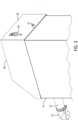
- Fig. 1 illustrates a flowable food product dispenser 10 constructed in accordance with an exemplary embodiment of the present disclosure.
- the term "flowable food product” or “food product” is meant to refer to a wide variety of products, such as condiments (i.e. ketchup, mustard, mayonnaise, tartar sauce, etc.), syrups, dressings, cheeses, fudge, caramel or other similar food products that can flow and thus be pumped.
- condiments i.e. ketchup, mustard, mayonnaise, tartar sauce, etc.
- syrups i.e. ketchup, mustard, mayonnaise, tartar sauce, etc.
- syrups i.e. ketchup, mustard, mayonnaise, tartar sauce, etc.
- dressings i.e. ketchup, mustard, mayonnaise, tartar sauce, etc.
- cheeses i.e. ketchup, mustard, mayonnaise, tartar sauce, etc.
- caramel i.e. ketchup, mustard
- the food product dispenser 10 includes a dispensing spout 12 that extends away from a main body 14.
- the dispensing spout 12 includes an outlet nozzle 16 that directs the food product onto the food item or into a condiment container.
- the main body 14 receives an automated pump actuation unit 17 that sits on top of the main body 14 during use of the food product dispenser 10.
- the automated pump actuation unit 17 is removable from the body 14 as a single unit, the significance of which will be described in detail below.
- the automated pump actuation unit 17 includes a touch-free, automated dispensing mechanism mounted within a cover member 18, the details of which will also be described in greater detail below. Although the automated pump actuation unit 17 is shown mounted within the cover member 18, other configurations are contemplated in which the automated dispensing mechanism could be mounted in other locations, such as within the main body 14, and would not be removable with the cover member 18.
- the cover member 18 includes a front face panel 20.
- the front face panel 20 includes a sensor window 22.
- the sensor window 22 is typically a clear area that provides the ability for an internal sensor to detect the presence of an actuation member, such as the hand of a user is in close proximity to the sensor. The details of the sensor and control system that form part of the automated pump actuation unit 17 will be described in greater detail below.
- the sensor window 22 is contained within a larger sensing area 24 that provides a visual indication to a user where the sensor is located.
- the main body 14 and the outer portions of the cover member 18 are formed from a durable material, such as stainless steel or durable plastic. Such material allows the main body 14 and cover member 18 to be cleaned and sanitized after periods of use.
- the back face 23 of the cover member 18 includes a power switch 25 and a connector 27 that secures the cover member 18 to the main body 14.
- Fig. 5 is a section view of the food product dispenser 10.
- the details of a pump assembly 26 are shown.
- the pump assembly 26 is a standard flexible diaphragm pump that has been utilized to dispense food products utilizing a variety of manual pump based food product dispensers, such as those available from Server Products.
- a flexible diaphragm pump is shown in the figures of the present application, it is contemplated that other pump assemblies could be used while operating within the scope of the present disclosure.
- the pump assembly 26 shown includes a hollow dispensing spout 12 that terminates at the nozzle 16.
- the dispensing spout 12 extends into a pump body 28 that has an internal pumping chamber 30.
- the pump assembly 26 further includes a pumping tube 32 that extends downward into the open interior 34 defined by the main body 14.
- the open interior 34 defines a reservoir designed to receive the supply of food product to be dispensed.
- the food product to be dispensed can be contained in a sealed pouch (not shown) or can be directly poured into the open interior 34 as shown in Fig. 5 .
- the pump tube 32 could include a pouch fitting 36 having a piercing end 38 that is designed to be received within a fitting of a condiment pouch (not shown). However, it is contemplated that the pouch fitting 36 could be removed and the pumping tube 32 could extend down into the supply of food product that is directly contained within the open interior 34 as shown in Fig. 5 .
- the main body 14 of the food product dispenser 10 includes an outer shell 37 that receives a removable liner 39.
- the removable liner 39 creates the open interior 34 and can be removed from the outer shell 37 for cleaning.
- the liner 39 includes a sloped bottom wall 40 that is used to direct the supply of condiment toward the pumping tube 32, whether the condiment is included in a bag or pouch or is directly received in the open interior 34.
- the pump assembly 26 is securely mounted to the main body 14 such that the pump assembly 26 is supported by the main body 14 independent from the cover member 18.
- the pump assembly 26 includes a flexible diaphragm 42 that extends from the pump body 28.
- pressure on the flexible diaphragm 42 pushes the food product out of the spout 12 through a one-way discharge valve 44.
- the flexible diaphragm 42 expands and creates a negative source of pressure that draws food product through a second one-way inflow valve 46.
- the operation of such a flexible diaphragm pump is well-known in the industry.
- the manual pump handle typically used with a flexible diaphragm pump is replaced with a touch free, automated pump actuation unit 17.
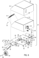
- the automated pump actuation unit 17 includes a mechanical actuator 48 and the cover member 18, which are shown in an exploded view in Fig. 6 .
- the mechanical actuator 48 is shown mounted to the interior of the cover member 18 such that the automated pump actuation unit 17 can be removed as a single unit from the main body 14 of the food product dispenser 10 as was shown in Fig. 2 .
- the mechanical actuator 48 operates to depress and release the diaphragm 42 such that the diaphragm acts in a known and conventional manner to pump food product from the food product dispenser.
- the mechanical actuator 48 operates in an automated fashion and eliminates any need for the customer or food service worker to touch a manual handle as in the prior systems.
- the cover member 18 includes an outer hood 50 and an inner hood 51 that are both formed from a metallic material, such as stainless steel. However, it is contemplated that the inner and outer hoods could be formed from another material that is easy to clean, such as plastic.
- the outer hood 50 includes the sloping front wall 52 that includes the sensing area 24 shown in Figs. 1 and 2 .
- a control board 54 is mounted to the inner surface 56 of the front wall 52.
- the control board 54 includes a control unit 61, such as a processor or CPU, along with a variety of other electronic operating components, including a sensor 58 that is designed to be aligned with the sensor window.
- the senor 58 is a capacitive proximity sensor that can sense the presence of an actuation member, such as user's hand, within a sensing area 59.
- the sensor 58 creates the sensing area 59 in the shape of a sensing cone that extends above the front wall 52. Whenever an actuation member, such as a hand or other body part of a user enters the sensing cone and remains in the sensing cone for a predetermined period of time, such as 1 second, the sensor 58 generates an output signal.
- the sensing area 59 created by the sensor 58 extends between one inch and six inches above the front wall 52.
- the sensor 58 is contemplated as being a capacitive sensor, other sensor types, such as an inductive sensor, photo sensor or magnetic sensor could be utilized to detect the presence of a user.
- control board 54 includes other operating components, such as a control unit 61 that may be comprised of an operating processor.
- the control board 54 can also include memory device 63 for storing operating instructions.
- the control board 54 could also include a wireless communication device 65 that would allow for wireless communication and monitoring of the food product dispenser from a near or remote location. For example, the remote monitoring would allow a foodservice company to monitor the amount of the food product that has been dispensed to predict when the dispenser would need to be refilled.
- the mechanical actuator 48 of the automated pump actuation unit 17 includes a support plate 60 that provides operative support for the components of the mechanical actuator 48 within the outer hood 50 of cover member 18 of the automated pump actuation unit 17.
- the support plate 60 is securely attached to the hood 50 by a series of connectors 62, as can be seen in Fig. 5 .
- the support plate 60 includes a mounting block 64 that provides a point of connection for an electric drive motor 66.
- the electric drive motor 66 includes an output drive shaft 68 that extends through the mounting block 64.
- the electric drive motor 66 is connected to a power supply and controlled by operation of the control unit 61.
- the power supply for driving the electric drive motor 66 can be either a connection to the utility power in the area near the food product dispenser or could be an internal battery power supply (not shown).
- the power supply could also include a specifically designed power supply designed to convert utility power to a desired voltage and current source for driving the electric drive motor 66 and the other components on the circuit board 54.
- the drive shaft 68 of the drive motor 66 can be connected to a cam 70 through the central attachment opening 72 formed in the cam 70.
- the cam 70 includes an attachment point 74 that is spaced radially outward from the center of the cam 70.
- the attachment point 74 provides a point of attachment for a first end 75 of a actuator arm 76.
- the first end 75 of the actuator arm 76 is connected to first end 75 of the cam 70 through use of a pivot pin 78.
- the outer end 80 of the actuator arm 76 receives and supports a roller 82.
- the roller 82 is rotatably supported on the second outer end 80 of the actuator arm 76 by a pin 84.
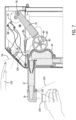
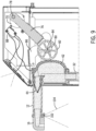
- the roller 82 is designed to move along the outer surface of the diaphragm 42 to compress the diaphragm 42, as can be seen in Fig. 8 . Further rotation of the cam 70 moves the roller 82 away from the diaphragm 42 to release the diaphragm 42 as shown in Fig. 9 .
- a wheel drive bracket arm 86 is also pivotally connected to help guide the movement of the roller 82 along the outer surface of the diaphragm 42.
- a switch 88 and spacer 90 are used to sense the movement of the cam 70, as is illustrated in the mounting arrangement of Fig. 5 .
- the switch 88 is in communication with the control unit 61 on the control board 54 to provide monitoring information to the control unit 61.
- the roller 82 moves along the outer surface of the diaphragm 42 to compress the diaphragm 42 and cause food product to be dispensed into a container 100 or onto another food product through the nozzle 16, as shown in Fig. 8 .
- further rotation of the cam 70 causes the roller to both retract away from the diaphragm and upward to the condition shown in Fig. 7 , thereby allowing the diaphragm 42 to create a negative source of pressure to draw additional food product into the pumping tube 32 in a conventional manner.
- a second sensor 102 can be included in the nozzle 16.
- the second sensor 102 creates a second sensing cone 104 that is able to determine whether a condiment container 100 is within the sensing cone 104.
- a control wire 106 leads back to the switch 88 such that the switch 88 will only activate the drive motor when the sensor 102 detects the presence of the condiment container 100.
- the sensor 102 can be one of multiple different sensor types, such as an optical sensor or inductive sensor. Although the sensor 102 is shown in several of the drawing figures, the sensor 102 can be eliminated and only the single sensor 58 utilized to trigger operation of the automated pump actuation unit 17.
- the second sensor 102 could be used to make sure that a container 100 or food product is located in a position to receive the food product before the food product is dispensed.
- the use of the automated pump actuation unit 17 can replace a conventional manual pump lever.
- the control unit 61 operates the drive motor 66 to rotate the drive shaft 68 a predetermined number of times to dispense the desired amount of food product.
- the control unit 61 will terminate operation of the drive motor 66 once the desired amount of food product has been dispensed. If the user removes his/her hand, the control unit 61 will reset and will begin the pumping operation again upon detection of the presence of the operator's hand.
- control unit can be programmed in various different manners to control the amount of material dispensed and the timing of the dispensing upon detecting the presence of a hand. Further, it is contemplated that the pumping can stop or start depending upon the presence of the operator's hand or can be programmed to dispense a predetermined amount of material each time the user's hand is detected.
- the entire automated pump actuation unit 17 can be removed from the main body 14 as a single unit.
- the automated pump actuation unit 17 is designed to engage the pump assembly 26 as the automated pump actuation unit 17 is placed on the top edge of the main body 14. Since the entire pump actuator 17, including the cover member 18, mechanical actuator 48, control unit 61 and sensor 58 are assembled as a single unit, the automated pump actuation unit 17 could be used to retrofit existing food product dispensers that include a mechanical actuation handle. In such retrofit application, the flexible diaphragm pump would remain installed on the main body and the existing cover member and mechanical actuation handle would be removed from the main body. Once removed, the automated pump actuation unit 17 would be attached to the top end of the main body such that the mechanical actuator 48 would come into contact with the flexible diaphragm of the flexible diaphragm pump.
- the automated pump actuation unit 17 would operate as described above to depress and release the flexible diaphragm to pump food product out of the main body.
- the automated pump actuation unit 17 of the present disclosure allows for existing manual food products dispensers to be upgraded to a touch-free dispenser without having to replace the existing main body and flexible diaphragm pump.
- the automated pump actuation unit 17 is designed such that all of the operating components are removable as a single unit to facilitate the conversion of food product dispensers in this manner.
- Fig. 10 is a schematic illustration of the components used to control the operation of the pump dispenser of the present disclosure. Many of the components shown in Fig. 10 are mounted to the control board contained within the cover member.
- the control unit 61 is operatively connected to many of the components to control the operation of the automated pump actuation unit.
- the control unit 61 is connected to the drive motor 66 such that the control unit 61 can control when and for how long the drive motor 66 operates. Since the operation of the drive motor 66 compresses and releases the diaphragm of the pump, the control unit 61 can control the amount of food product dispensed each time the hand of the user is detected. In one embodiment, the control unit 61 operates to dispense a defined volume of food product, such as 1 ounce, each time the hand of the user is detected. However, the owner/operator of the dispenser can change this amount depending upon the specific application.
- a wireless communication device 65 allows the user to communicate with the control unit 61 to set various operating parameter, such as the amount of food product dispensed upon detection of the hand of the user.
- the operating parameters can be stored in the memory device 63.
- the control unit 61 can also control how long the hand of the user must be detected by the sensor 58 until the drive motor 66 is activated.
- the control unit 61 can be programmed to active the drive motor 66 only when the hand has been continuously detected for one second. This parameter can also be modified by the user through communication to the control unit 61.
- the second sensor 102 detect whether a hand, condiment holder or food item is below the dispensing spout 16.
- the second senor 102 is shown connected to the sensing switch 88.
- the sensing switch 88 is connected to both the control unit 61 and the drive motor.
- the sensing switch 88 allows the control unit 61 to monitor the operation of the drive motor 66 and prevents operation of the drive motor 66 when the second sensor 102 does not detect a hand, container or food item.
- the second sensor 102 is optional and is not required for operation of the dispenser.
- a cover detector switch 111 is positioned to detect when the cover member 18 is properly positioned on the main body of the dispenser. If the cover member is not properly installed, the control unit 61 will not allow the drive motor 66 to operate.
- the cover detector switch 111 is also shown in Fig. 6 and is mounted to a mounting plate 112 that extends perpendicular to the mounting plate 60.
- the cover detector switch 111 includes a wheel 114 that retracts when the cover member 18 is mounted to the main body. Specifically, the wheel 114 contacts the upper flange 116 on the main body 14, which is shown in Fig. 2 .
- the front end of the cover member 18 is initially connected to the main body 14 and the cover member 18 pivots downward until the wheel 114 contacts the upper flange, causing the cover detector switch 111 to indicate attachment of the cover member 18 to the main body 14.
Landscapes
- Engineering & Computer Science (AREA)
- Food Science & Technology (AREA)
- Mechanical Engineering (AREA)
- Devices For Dispensing Beverages (AREA)
- Reciprocating Pumps (AREA)
Claims (10)
- Spender (10) für fließfähige Nahrungsmittel, der betreibbar ist, um selektiv ein Nahrungsmittel nach Wunsch durch einen Benutzer abzugeben, umfassend:einen Hauptkörper (14), der ein offenes Inneres (34) aufweist, das dazu bemessen ist, eine Versorgung fließfähigen Nahrungsmittels, das abgegeben werden soll, aufzunehmen;eine Pumpenanordnung (26), die auf dem Hauptkörper (14) getragen wird, wobei die Pumpenanordnung ein erstes Ende in Fluidkommunikation mit der Zufuhr fließfähigen Nahrungsmittels und ein Abgabeende, das sich von dem Hauptkörper (14) erstreckt, beinhaltet, wobei die Pumpenanordnung (26) eine Membranpumpe beinhaltet, die Folgendes umfasst: ein Pumprohr (32), das das erste Ende in Fluidkommunikation mit der Versorgung fließfähigen Nahrungsmittels beinhaltet; eine Abgabetülle (16), die sich von dem Hauptkörper (14) erstreckt und das Abgabeende beinhaltet; und einen Pumpenkörper (28), der zwischen dem Pumprohr (32) und der Abgabetülle (16) positioniert ist, wobei der Pumpenkörper (28) eine biegsame Membran (42) beinhaltet, die gedrückt und freigegeben werden kann, um fließbares Nahrungsmittel durch die Pumpenanordnung (26) abzuzapfen;eine automatisierte Pumpenbetätigungseinheit (17), die betreibbar ist, um die Pumpenanordnung (26) zu betätigen, um die Zufuhr für fließbaren Nahrungsmittels aus der Zufuhr abzuzapfen und das fließbare Nahrungsmittel aus dem Abgabeende der Pumpenanordnung (26) abzugeben;ein Abdeckelement (18), das auf dem Hauptkörper (14) getragen wird, wobei die automatisierte Pumpenbetätigungseinheit (17) an das Abdeckelement (18) derart montiert ist, dass das Abdeckelement (18) und die automatisierte Pumpenbetätigungseinheit (17) von dem Hauptkörper (14) als eine einzige Einheit abnehmbar sind; undeinen Sensor (52), der positioniert ist, um das Vorhandensein eines Betätigungselements in der Nähe des Sensors (52) zu erfassen,und wobei die automatisierte Pumpenbetätigungseinheit (17) betreibbar ist, um automatisch die Pumpenanordnung (26) bei Erfassen des Vorhandenseins des Betätigungselements zu betätigen
- Nahrungsmittelspender (10) nach Anspruch 1, wobei das Betätigungselement eine Hand des Benutzers ist.
- Nahrungsmittelspender (10) nach Anspruch 1, wobei die automatisierte Pumpenbetätigungseinheit (17) einen mechanischen Aktuator (48) beinhaltet, der einen Antriebsmotor (66) und einen Aktuatorsarm (76) beinhaltet, der in Kontakt mit der biegsamen Membran (42) positioniert ist, wobei der Antriebsmotor (66) betreibbar ist, um den Aktuatorarm (76) zu veranlassen, die biegsame Membran (42) zu drücken und freizugeben.
- Nahrungsmittelspender (10) nach Anspruch 3, der ferner eine Walze (82) umfasst, die an den Aktuatorarm (76) montiert ist, wobei der Antriebsmotor (66) den Aktuatorarm (76) bewegt, um die Walze (82) zu veranlassen, die biegsame Membran (42) zu drücken und freizugeben.
- Nahrungsmittelspender (10) nach Anspruch 3, wobei die automatisierte Betätigungseinheit (17) in die biegsame Membran (42) eingreift, wenn das Abdeckelement (18) auf dem Hauptkörper (14) installiert ist.
- Nahrungsmittelspender (10) nach Anspruch 1, wobei der Sensor (52) an das Abdeckelement (18) montiert ist und das Vorhandensein des Betätigungselements über der Abdeckung erfasst.
- Nahrungsmittelspender (10) nach Anspruch 1, wobei die automatisierte Pumpenbetätigungseinheit (17) betreibbar ist, um die Pumpenanordnung (26) automatisch zu betreiben, um ein ausgewähltes Volumen fließfähigen Nahrungsmittels bei Erfassung des Betätigungselements abzugeben.
- Nahrungsmittelspender (10) nach Anspruch 1, wobei die automatisierte Pumpenbetätigungseinheit (17) bei Erfassen des Vorhandenseins des Betätigungselements länger als eine Abtastperiode arbeitet.
- Nahrungsmittelspender (10) nach Anspruch 1, wobei die Zufuhr fließfähigen Nahrungsmittels in einem biegsamen Beutel enthalten ist.
- Nahrungsmittelspender (10) nach Anspruch 1, wobei die Zufuhr fließfähigen Nahrungsmittels direkt innerhalb des offenen Inneren (34) des Hauptkörpers (14) aufgenommen ist.
Applications Claiming Priority (3)
| Application Number | Priority Date | Filing Date | Title |
|---|---|---|---|
| US202063055508P | 2020-07-23 | 2020-07-23 | |
| US17/108,468 US10961105B1 (en) | 2020-07-23 | 2020-12-01 | Touch-free flowable food product dispenser |
| PCT/US2021/025165 WO2022019966A1 (en) | 2020-07-23 | 2021-03-31 | Touch-free flowable food product dispenser |
Publications (2)
| Publication Number | Publication Date |
|---|---|
| EP4185159A1 EP4185159A1 (de) | 2023-05-31 |
| EP4185159B1 true EP4185159B1 (de) | 2024-09-18 |
Family
ID=75164561
Family Applications (1)
| Application Number | Title | Priority Date | Filing Date |
|---|---|---|---|
| EP21720365.2A Active EP4185159B1 (de) | 2020-07-23 | 2021-03-31 | Berührungsloser spender für fliessfähige nahrungsmittel |
Country Status (4)
| Country | Link |
|---|---|
| US (2) | US10961105B1 (de) |
| EP (1) | EP4185159B1 (de) |
| CA (2) | CA3224543A1 (de) |
| WO (1) | WO2022019966A1 (de) |
Families Citing this family (6)
| Publication number | Priority date | Publication date | Assignee | Title |
|---|---|---|---|---|
| US10961105B1 (en) * | 2020-07-23 | 2021-03-30 | Server Products, Inc. | Touch-free flowable food product dispenser |
| CA3189925A1 (en) * | 2020-07-24 | 2022-01-27 | H.J. Heinz Company Brands Llc | Condiment dispenser |
| US11304570B1 (en) * | 2021-01-22 | 2022-04-19 | Intelwrist, Llc | Multifunctional wearable fluid dispensing apparatus |
| GB2608448A (en) * | 2021-07-02 | 2023-01-04 | Green Adam | Contactless conrtrol unit for a dispenser |
| WO2023283210A1 (en) * | 2021-07-06 | 2023-01-12 | H.J. Heinz Company Brands Llc | Condiment dispensing apparatus, system, and methods of use |
| WO2025250475A1 (en) * | 2024-05-27 | 2025-12-04 | Server Products, Inc. | System and method for dispensing food product |
Citations (1)
| Publication number | Priority date | Publication date | Assignee | Title |
|---|---|---|---|---|
| US20070000941A1 (en) * | 2005-07-01 | 2007-01-04 | Hadden David M | Motion-activated soap dispenser |
Family Cites Families (46)
| Publication number | Priority date | Publication date | Assignee | Title |
|---|---|---|---|---|
| US4722372A (en) * | 1985-08-02 | 1988-02-02 | Louis Hoffman Associates Inc. | Electrically operated dispensing apparatus and disposable container useable therewith |
| US4921150A (en) | 1988-08-26 | 1990-05-01 | Pandel Instruments, Inc. | Automatic dispensing apparatus having low power consumption |
| SE505827C2 (sv) | 1993-09-07 | 1997-10-13 | Asept Int Ab | Portioneringsanordning för att portionera ut flytande livsmedel ur en livsmedelsbehållare |
| US5492247A (en) * | 1994-06-02 | 1996-02-20 | Shu; Aling | Automatic soap dispenser |
| JPH0835487A (ja) | 1994-07-22 | 1996-02-06 | Ikari Shodoku Kk | 定量供給用のチューブポンプおよび定量供給装置 |
| US5611465A (en) * | 1995-03-20 | 1997-03-18 | Lee; Kuo-Chou | Automatic toilet bowl cleaner |
| CA2278239C (en) | 1997-01-17 | 2003-12-23 | Niagara Pump Corporation | Linear peristaltic pump |
| US6036056A (en) * | 1997-05-05 | 2000-03-14 | Lee; Kuo-Chou | Automatic soap dispensing device |
| JP2000145646A (ja) | 1998-11-16 | 2000-05-26 | Tanika Denki Hanbai Kk | 膜ポンプ機構とこれを有する酒サーバー |
| US6152330A (en) * | 1999-02-11 | 2000-11-28 | Chester Labs, Inc. | Hinged dispenser housing |
| US6089406A (en) | 1999-06-01 | 2000-07-18 | Server Products | Packaged food warmer and dispenser |
| US6431400B1 (en) * | 2000-03-21 | 2002-08-13 | Ultraclenz Engineering Group | Dispenser apparatus that controls the type and brand of the product dispensed therefrom |
| SE524487C2 (sv) | 2000-09-29 | 2004-08-17 | Asept Int Ab | Anordning för att förhindra att en förpackning och en icke till denna hörande utmatningsanordning kan kopplas till varandra |
| US6390329B1 (en) * | 2000-10-10 | 2002-05-21 | Joseph S. Kanfer | Apparatus for hands-free dispensing of a measured quantity of material |
| US6543651B2 (en) * | 2000-12-19 | 2003-04-08 | Kimberly-Clark Worldwide, Inc. | Self-contained viscous liquid dispenser |
| US6662971B1 (en) * | 2002-04-10 | 2003-12-16 | Ryan R. Nguyen | Automatic pressing mechanism |
| US7191920B2 (en) | 2002-09-25 | 2007-03-20 | Conopco, Inc. | Motorized household liquid dispenser |
| GB2394941B (en) * | 2002-11-04 | 2005-02-16 | Kimberly Clark Co | Viscous liquid dispensing pump |
| US7007824B2 (en) * | 2003-01-24 | 2006-03-07 | Baxter International Inc. | Liquid dispenser and flexible bag therefor |
| EP1606213B1 (de) * | 2003-03-21 | 2011-05-04 | Kanfer, Joseph S. | Vorrichtung zur handfreien abgabe einer dosierten materialmenge |
| US7028861B2 (en) * | 2003-12-16 | 2006-04-18 | Joseph S. Kanfer | Electronically keyed dispensing systems and related methods of installation and use |
| US7527178B2 (en) * | 2003-12-30 | 2009-05-05 | Kimberly-Clark Worldwide, Inc. | Electronic viscous liquid dispenser |
| US7621426B2 (en) * | 2004-12-15 | 2009-11-24 | Joseph Kanfer | Electronically keyed dispensing systems and related methods utilizing near field frequency response |
| US20060249531A1 (en) * | 2005-05-09 | 2006-11-09 | Litchfield Richard J | Motion Activated Food Dispenser |
| US7281643B2 (en) * | 2005-06-14 | 2007-10-16 | Po-Hui Lin | Automatic soap dispenser structure |
| US8336740B1 (en) * | 2005-11-02 | 2012-12-25 | Daansen Warren S | Fluid dispenser and pump adapter system therefor |
| US8096445B2 (en) | 2007-02-01 | 2012-01-17 | Simplehuman, Llc | Electric soap dispenser |
| ES2374041T3 (es) | 2008-06-20 | 2012-02-13 | Gojo Industries, Inc. | Bomba de espuma de diafragma. |
| US8240508B2 (en) * | 2008-12-29 | 2012-08-14 | Gojo Industries, Inc. | Low cost radio frequency identification (RFID) dispensing systems |
| US8342365B2 (en) * | 2009-06-08 | 2013-01-01 | Ultraclenz, Llc | Touch-free pressurized can dispenser |
| GB0915826D0 (en) * | 2009-09-10 | 2009-10-07 | Imi Cornelius Uk Ltd | Foodstuff dispenser |
| US8651329B2 (en) * | 2009-11-12 | 2014-02-18 | Gojo Industries, Inc. | Methods for resetting stalled pumps in electronically controlled dispensing systems |
| US8646655B2 (en) * | 2009-11-12 | 2014-02-11 | Gojo Industries, Inc. | Methods for resetting stalled pumps in electronically controlled dispensing systems |
| CN103402650B (zh) * | 2010-03-17 | 2016-07-20 | Ipnip有限公司 | 具有部分分配装置的容器 |
| US8622242B2 (en) * | 2010-04-16 | 2014-01-07 | Gojo Industries, Inc. | Taggant keying system for dispensing systems |
| GB201007232D0 (en) * | 2010-04-30 | 2010-06-16 | Reckitt & Colman Overseas | A liquid delivery system |
| US20140231460A1 (en) * | 2013-02-15 | 2014-08-21 | Ecolab Usa Inc. | Focusing location of antimicrobial additives in fluid dispensers |
| US8950628B2 (en) | 2013-03-15 | 2015-02-10 | San Jamar, Inc. | Through surface dual function fluid dispensing system |
| WO2015048698A1 (en) * | 2013-09-30 | 2015-04-02 | Gojo Industries, Inc | Dispensers, refill units and pumps having suck-back features |
| KR20160070097A (ko) | 2013-10-11 | 2016-06-17 | 겔 푸즈, 엘엘씨 | 식품 제품 분배기 및 밸브 |
| US9809439B2 (en) * | 2014-09-08 | 2017-11-07 | Ernest F. FALCO, III | Sanitary touch-free automatic condiment dispensing apparatus and method of use |
| US10464800B2 (en) | 2016-07-27 | 2019-11-05 | DraftServ Technologies, LLC | Systems and methods for dispensing and tracking multiple categories of beverages |
| US10373477B1 (en) * | 2016-09-28 | 2019-08-06 | Gojo Industries, Inc. | Hygiene compliance modules for dispensers, dispensers and compliance monitoring systems |
| US20200282414A1 (en) | 2019-03-09 | 2020-09-10 | A. J. Antunes & Co. | Automatic sauce dispensing system |
| US11683623B2 (en) | 2019-06-24 | 2023-06-20 | Linda Hunt | Device comprising sensor-activated dispensing and auditory tone |
| US10961105B1 (en) * | 2020-07-23 | 2021-03-30 | Server Products, Inc. | Touch-free flowable food product dispenser |
-
2020
- 2020-12-01 US US17/108,468 patent/US10961105B1/en active Active
-
2021
- 2021-03-05 US US17/193,575 patent/US11472692B2/en active Active
- 2021-03-31 EP EP21720365.2A patent/EP4185159B1/de active Active
- 2021-03-31 CA CA3224543A patent/CA3224543A1/en active Pending
- 2021-03-31 CA CA3185548A patent/CA3185548C/en active Active
- 2021-03-31 WO PCT/US2021/025165 patent/WO2022019966A1/en not_active Ceased
Patent Citations (1)
| Publication number | Priority date | Publication date | Assignee | Title |
|---|---|---|---|---|
| US20070000941A1 (en) * | 2005-07-01 | 2007-01-04 | Hadden David M | Motion-activated soap dispenser |
Also Published As
| Publication number | Publication date |
|---|---|
| CA3185548A1 (en) | 2022-01-27 |
| WO2022019966A1 (en) | 2022-01-27 |
| US11472692B2 (en) | 2022-10-18 |
| CA3224543A1 (en) | 2022-01-27 |
| US20220024749A1 (en) | 2022-01-27 |
| US10961105B1 (en) | 2021-03-30 |
| EP4185159A1 (de) | 2023-05-31 |
| CA3185548C (en) | 2024-02-13 |
Similar Documents
| Publication | Publication Date | Title |
|---|---|---|
| EP4185159B1 (de) | Berührungsloser spender für fliessfähige nahrungsmittel | |
| US8342365B2 (en) | Touch-free pressurized can dispenser | |
| US8783511B2 (en) | Manual and touch-free convertible fluid dispenser | |
| EP2322067B1 (de) | Verfahren zum Zurücksetzen von blockierten Pumpen in elektronisch gesteuerten Abgabesystemen | |
| EP2734096B1 (de) | Spender mit optischem eingabesystem | |
| US6607103B2 (en) | Touch free dispenser | |
| US11759060B2 (en) | Portable consumer liquid pump | |
| US20040226962A1 (en) | Automatic liquid dispenser | |
| CA2842701C (en) | Methods for resetting stalled pumps in electronically controlled dispensing systems | |
| US20140312060A1 (en) | Dosing spout and system | |
| US6814262B1 (en) | Disposable pump and drive mechanism for dispensing a liquid food product | |
| EP2729403A1 (de) | Spender für flüssigkeitsportionen | |
| CA2390219A1 (en) | System and method for dispensing soap | |
| JP7175400B2 (ja) | 配分制御装置、及び配分設備 | |
| CA2639374C (en) | Low profile dispenser | |
| US20230190020A1 (en) | Systems, methods and apparatus for touchless dispensing | |
| US20250115468A1 (en) | Flowable food product dispenser with automated portion control | |
| HK1153918A (en) | Methods for resetting stalled pumps in electronically controlled dispensing systems |
Legal Events
| Date | Code | Title | Description |
|---|---|---|---|
| STAA | Information on the status of an ep patent application or granted ep patent |
Free format text: STATUS: UNKNOWN |
|
| STAA | Information on the status of an ep patent application or granted ep patent |
Free format text: STATUS: THE INTERNATIONAL PUBLICATION HAS BEEN MADE |
|
| PUAI | Public reference made under article 153(3) epc to a published international application that has entered the european phase |
Free format text: ORIGINAL CODE: 0009012 |
|
| STAA | Information on the status of an ep patent application or granted ep patent |
Free format text: STATUS: REQUEST FOR EXAMINATION WAS MADE |
|
| 17P | Request for examination filed |
Effective date: 20230118 |
|
| AK | Designated contracting states |
Kind code of ref document: A1 Designated state(s): AL AT BE BG CH CY CZ DE DK EE ES FI FR GB GR HR HU IE IS IT LI LT LU LV MC MK MT NL NO PL PT RO RS SE SI SK SM TR |
|
| DAV | Request for validation of the european patent (deleted) | ||
| DAX | Request for extension of the european patent (deleted) | ||
| STAA | Information on the status of an ep patent application or granted ep patent |
Free format text: STATUS: EXAMINATION IS IN PROGRESS |
|
| 17Q | First examination report despatched |
Effective date: 20231106 |
|
| GRAP | Despatch of communication of intention to grant a patent |
Free format text: ORIGINAL CODE: EPIDOSNIGR1 |
|
| STAA | Information on the status of an ep patent application or granted ep patent |
Free format text: STATUS: GRANT OF PATENT IS INTENDED |
|
| INTG | Intention to grant announced |
Effective date: 20240417 |
|
| GRAS | Grant fee paid |
Free format text: ORIGINAL CODE: EPIDOSNIGR3 |
|
| GRAA | (expected) grant |
Free format text: ORIGINAL CODE: 0009210 |
|
| STAA | Information on the status of an ep patent application or granted ep patent |
Free format text: STATUS: THE PATENT HAS BEEN GRANTED |
|
| AK | Designated contracting states |
Kind code of ref document: B1 Designated state(s): AL AT BE BG CH CY CZ DE DK EE ES FI FR GB GR HR HU IE IS IT LI LT LU LV MC MK MT NL NO PL PT RO RS SE SI SK SM TR |
|
| REG | Reference to a national code |
Ref country code: GB Ref legal event code: FG4D |
|
| REG | Reference to a national code |
Ref country code: CH Ref legal event code: EP |
|
| REG | Reference to a national code |
Ref country code: DE Ref legal event code: R096 Ref document number: 602021018976 Country of ref document: DE |
|
| P01 | Opt-out of the competence of the unified patent court (upc) registered |
Free format text: CASE NUMBER: APP_49271/2024 Effective date: 20240830 |
|
| REG | Reference to a national code |
Ref country code: IE Ref legal event code: FG4D |
|
| REG | Reference to a national code |
Ref country code: SE Ref legal event code: TRGR |
|
| REG | Reference to a national code |
Ref country code: LT Ref legal event code: MG9D |
|
| PG25 | Lapsed in a contracting state [announced via postgrant information from national office to epo] |
Ref country code: NO Free format text: LAPSE BECAUSE OF FAILURE TO SUBMIT A TRANSLATION OF THE DESCRIPTION OR TO PAY THE FEE WITHIN THE PRESCRIBED TIME-LIMIT Effective date: 20241218 |
|
| PG25 | Lapsed in a contracting state [announced via postgrant information from national office to epo] |
Ref country code: GR Free format text: LAPSE BECAUSE OF FAILURE TO SUBMIT A TRANSLATION OF THE DESCRIPTION OR TO PAY THE FEE WITHIN THE PRESCRIBED TIME-LIMIT Effective date: 20241219 Ref country code: FI Free format text: LAPSE BECAUSE OF FAILURE TO SUBMIT A TRANSLATION OF THE DESCRIPTION OR TO PAY THE FEE WITHIN THE PRESCRIBED TIME-LIMIT Effective date: 20240918 |
|
| PG25 | Lapsed in a contracting state [announced via postgrant information from national office to epo] |
Ref country code: BG Free format text: LAPSE BECAUSE OF FAILURE TO SUBMIT A TRANSLATION OF THE DESCRIPTION OR TO PAY THE FEE WITHIN THE PRESCRIBED TIME-LIMIT Effective date: 20240918 |
|
| PG25 | Lapsed in a contracting state [announced via postgrant information from national office to epo] |
Ref country code: LV Free format text: LAPSE BECAUSE OF FAILURE TO SUBMIT A TRANSLATION OF THE DESCRIPTION OR TO PAY THE FEE WITHIN THE PRESCRIBED TIME-LIMIT Effective date: 20240918 |
|
| PG25 | Lapsed in a contracting state [announced via postgrant information from national office to epo] |
Ref country code: HR Free format text: LAPSE BECAUSE OF FAILURE TO SUBMIT A TRANSLATION OF THE DESCRIPTION OR TO PAY THE FEE WITHIN THE PRESCRIBED TIME-LIMIT Effective date: 20240918 |
|
| REG | Reference to a national code |
Ref country code: NL Ref legal event code: MP Effective date: 20240918 |
|
| PG25 | Lapsed in a contracting state [announced via postgrant information from national office to epo] |
Ref country code: RS Free format text: LAPSE BECAUSE OF FAILURE TO SUBMIT A TRANSLATION OF THE DESCRIPTION OR TO PAY THE FEE WITHIN THE PRESCRIBED TIME-LIMIT Effective date: 20241218 |
|
| PG25 | Lapsed in a contracting state [announced via postgrant information from national office to epo] |
Ref country code: RS Free format text: LAPSE BECAUSE OF FAILURE TO SUBMIT A TRANSLATION OF THE DESCRIPTION OR TO PAY THE FEE WITHIN THE PRESCRIBED TIME-LIMIT Effective date: 20241218 Ref country code: NO Free format text: LAPSE BECAUSE OF FAILURE TO SUBMIT A TRANSLATION OF THE DESCRIPTION OR TO PAY THE FEE WITHIN THE PRESCRIBED TIME-LIMIT Effective date: 20241218 Ref country code: LV Free format text: LAPSE BECAUSE OF FAILURE TO SUBMIT A TRANSLATION OF THE DESCRIPTION OR TO PAY THE FEE WITHIN THE PRESCRIBED TIME-LIMIT Effective date: 20240918 Ref country code: HR Free format text: LAPSE BECAUSE OF FAILURE TO SUBMIT A TRANSLATION OF THE DESCRIPTION OR TO PAY THE FEE WITHIN THE PRESCRIBED TIME-LIMIT Effective date: 20240918 Ref country code: GR Free format text: LAPSE BECAUSE OF FAILURE TO SUBMIT A TRANSLATION OF THE DESCRIPTION OR TO PAY THE FEE WITHIN THE PRESCRIBED TIME-LIMIT Effective date: 20241219 Ref country code: FI Free format text: LAPSE BECAUSE OF FAILURE TO SUBMIT A TRANSLATION OF THE DESCRIPTION OR TO PAY THE FEE WITHIN THE PRESCRIBED TIME-LIMIT Effective date: 20240918 Ref country code: BG Free format text: LAPSE BECAUSE OF FAILURE TO SUBMIT A TRANSLATION OF THE DESCRIPTION OR TO PAY THE FEE WITHIN THE PRESCRIBED TIME-LIMIT Effective date: 20240918 |
|
| REG | Reference to a national code |
Ref country code: AT Ref legal event code: MK05 Ref document number: 1723957 Country of ref document: AT Kind code of ref document: T Effective date: 20240918 |
|
| PG25 | Lapsed in a contracting state [announced via postgrant information from national office to epo] |
Ref country code: NL Free format text: LAPSE BECAUSE OF FAILURE TO SUBMIT A TRANSLATION OF THE DESCRIPTION OR TO PAY THE FEE WITHIN THE PRESCRIBED TIME-LIMIT Effective date: 20240918 |
|
| PG25 | Lapsed in a contracting state [announced via postgrant information from national office to epo] |
Ref country code: PT Free format text: LAPSE BECAUSE OF FAILURE TO SUBMIT A TRANSLATION OF THE DESCRIPTION OR TO PAY THE FEE WITHIN THE PRESCRIBED TIME-LIMIT Effective date: 20250120 Ref country code: IS Free format text: LAPSE BECAUSE OF FAILURE TO SUBMIT A TRANSLATION OF THE DESCRIPTION OR TO PAY THE FEE WITHIN THE PRESCRIBED TIME-LIMIT Effective date: 20250118 |
|
| PG25 | Lapsed in a contracting state [announced via postgrant information from national office to epo] |
Ref country code: RO Free format text: LAPSE BECAUSE OF FAILURE TO SUBMIT A TRANSLATION OF THE DESCRIPTION OR TO PAY THE FEE WITHIN THE PRESCRIBED TIME-LIMIT Effective date: 20240918 Ref country code: SM Free format text: LAPSE BECAUSE OF FAILURE TO SUBMIT A TRANSLATION OF THE DESCRIPTION OR TO PAY THE FEE WITHIN THE PRESCRIBED TIME-LIMIT Effective date: 20240918 |
|
| PG25 | Lapsed in a contracting state [announced via postgrant information from national office to epo] |
Ref country code: ES Free format text: LAPSE BECAUSE OF FAILURE TO SUBMIT A TRANSLATION OF THE DESCRIPTION OR TO PAY THE FEE WITHIN THE PRESCRIBED TIME-LIMIT Effective date: 20240918 |
|
| PG25 | Lapsed in a contracting state [announced via postgrant information from national office to epo] |
Ref country code: EE Free format text: LAPSE BECAUSE OF FAILURE TO SUBMIT A TRANSLATION OF THE DESCRIPTION OR TO PAY THE FEE WITHIN THE PRESCRIBED TIME-LIMIT Effective date: 20240918 Ref country code: AT Free format text: LAPSE BECAUSE OF FAILURE TO SUBMIT A TRANSLATION OF THE DESCRIPTION OR TO PAY THE FEE WITHIN THE PRESCRIBED TIME-LIMIT Effective date: 20240918 |
|
| PG25 | Lapsed in a contracting state [announced via postgrant information from national office to epo] |
Ref country code: CZ Free format text: LAPSE BECAUSE OF FAILURE TO SUBMIT A TRANSLATION OF THE DESCRIPTION OR TO PAY THE FEE WITHIN THE PRESCRIBED TIME-LIMIT Effective date: 20240918 Ref country code: PL Free format text: LAPSE BECAUSE OF FAILURE TO SUBMIT A TRANSLATION OF THE DESCRIPTION OR TO PAY THE FEE WITHIN THE PRESCRIBED TIME-LIMIT Effective date: 20240918 |
|
| PG25 | Lapsed in a contracting state [announced via postgrant information from national office to epo] |
Ref country code: IT Free format text: LAPSE BECAUSE OF FAILURE TO SUBMIT A TRANSLATION OF THE DESCRIPTION OR TO PAY THE FEE WITHIN THE PRESCRIBED TIME-LIMIT Effective date: 20240918 Ref country code: SK Free format text: LAPSE BECAUSE OF FAILURE TO SUBMIT A TRANSLATION OF THE DESCRIPTION OR TO PAY THE FEE WITHIN THE PRESCRIBED TIME-LIMIT Effective date: 20240918 |
|
| REG | Reference to a national code |
Ref country code: DE Ref legal event code: R097 Ref document number: 602021018976 Country of ref document: DE |
|
| PG25 | Lapsed in a contracting state [announced via postgrant information from national office to epo] |
Ref country code: DK Free format text: LAPSE BECAUSE OF FAILURE TO SUBMIT A TRANSLATION OF THE DESCRIPTION OR TO PAY THE FEE WITHIN THE PRESCRIBED TIME-LIMIT Effective date: 20240918 |
|
| PLBE | No opposition filed within time limit |
Free format text: ORIGINAL CODE: 0009261 |
|
| STAA | Information on the status of an ep patent application or granted ep patent |
Free format text: STATUS: NO OPPOSITION FILED WITHIN TIME LIMIT |
|
| 26N | No opposition filed |
Effective date: 20250619 |
|
| REG | Reference to a national code |
Ref country code: DE Ref legal event code: R119 Ref document number: 602021018976 Country of ref document: DE |
|
| PG25 | Lapsed in a contracting state [announced via postgrant information from national office to epo] |
Ref country code: MC Free format text: LAPSE BECAUSE OF FAILURE TO SUBMIT A TRANSLATION OF THE DESCRIPTION OR TO PAY THE FEE WITHIN THE PRESCRIBED TIME-LIMIT Effective date: 20240918 |
|
| REG | Reference to a national code |
Ref country code: CH Ref legal event code: H13 Free format text: ST27 STATUS EVENT CODE: U-0-0-H10-H13 (AS PROVIDED BY THE NATIONAL OFFICE) Effective date: 20251023 |
|
| PG25 | Lapsed in a contracting state [announced via postgrant information from national office to epo] |
Ref country code: LU Free format text: LAPSE BECAUSE OF NON-PAYMENT OF DUE FEES Effective date: 20250331 |
|
| GBPC | Gb: european patent ceased through non-payment of renewal fee |
Effective date: 20250331 |
|
| REG | Reference to a national code |
Ref country code: BE Ref legal event code: MM Effective date: 20250331 |
|
| PG25 | Lapsed in a contracting state [announced via postgrant information from national office to epo] |
Ref country code: DE Free format text: LAPSE BECAUSE OF NON-PAYMENT OF DUE FEES Effective date: 20251001 |
|
| PG25 | Lapsed in a contracting state [announced via postgrant information from national office to epo] |
Ref country code: GB Free format text: LAPSE BECAUSE OF NON-PAYMENT OF DUE FEES Effective date: 20250331 |
|
| PG25 | Lapsed in a contracting state [announced via postgrant information from national office to epo] |
Ref country code: FR Free format text: LAPSE BECAUSE OF NON-PAYMENT OF DUE FEES Effective date: 20250331 |
|
| PG25 | Lapsed in a contracting state [announced via postgrant information from national office to epo] |
Ref country code: BE Free format text: LAPSE BECAUSE OF NON-PAYMENT OF DUE FEES Effective date: 20250331 |
|
| PG25 | Lapsed in a contracting state [announced via postgrant information from national office to epo] |
Ref country code: CH Free format text: LAPSE BECAUSE OF NON-PAYMENT OF DUE FEES Effective date: 20250331 |
|
| PG25 | Lapsed in a contracting state [announced via postgrant information from national office to epo] |
Ref country code: IE Free format text: LAPSE BECAUSE OF NON-PAYMENT OF DUE FEES Effective date: 20250331 |
|
| PGFP | Annual fee paid to national office [announced via postgrant information from national office to epo] |
Ref country code: SE Payment date: 20260323 Year of fee payment: 6 |