EP4185199B1 - Turbine améliorée pour spiromètre - Google Patents
Turbine améliorée pour spiromètre Download PDFInfo
- Publication number
- EP4185199B1 EP4185199B1 EP21743586.6A EP21743586A EP4185199B1 EP 4185199 B1 EP4185199 B1 EP 4185199B1 EP 21743586 A EP21743586 A EP 21743586A EP 4185199 B1 EP4185199 B1 EP 4185199B1
- Authority
- EP
- European Patent Office
- Prior art keywords
- section
- blade
- air
- rotor
- turbine
- Prior art date
- Legal status (The legal status is an assumption and is not a legal conclusion. Google has not performed a legal analysis and makes no representation as to the accuracy of the status listed.)
- Active
Links
Images




Classifications
-
- A—HUMAN NECESSITIES
- A61—MEDICAL OR VETERINARY SCIENCE; HYGIENE
- A61B—DIAGNOSIS; SURGERY; IDENTIFICATION
- A61B5/00—Measuring for diagnostic purposes; Identification of persons
- A61B5/08—Measuring devices for evaluating the respiratory organs
- A61B5/087—Measuring breath flow
- A61B5/09—Measuring breath flow using an element rotated by the flow
-
- A—HUMAN NECESSITIES
- A61—MEDICAL OR VETERINARY SCIENCE; HYGIENE
- A61B—DIAGNOSIS; SURGERY; IDENTIFICATION
- A61B5/00—Measuring for diagnostic purposes; Identification of persons
- A61B5/08—Measuring devices for evaluating the respiratory organs
- A61B5/087—Measuring breath flow
- A61B5/0873—Measuring breath flow using optical means
-
- A—HUMAN NECESSITIES
- A61—MEDICAL OR VETERINARY SCIENCE; HYGIENE
- A61B—DIAGNOSIS; SURGERY; IDENTIFICATION
- A61B5/00—Measuring for diagnostic purposes; Identification of persons
- A61B5/08—Measuring devices for evaluating the respiratory organs
- A61B5/097—Devices for facilitating collection of breath or for directing breath into or through measuring devices
-
- G—PHYSICS
- G01—MEASURING; TESTING
- G01F—MEASURING VOLUME, VOLUME FLOW, MASS FLOW OR LIQUID LEVEL; METERING BY VOLUME
- G01F1/00—Measuring the volume flow or mass flow of fluid or fluent solid material wherein the fluid passes through a meter in a continuous flow
- G01F1/05—Measuring the volume flow or mass flow of fluid or fluent solid material wherein the fluid passes through a meter in a continuous flow by using mechanical effects
- G01F1/10—Measuring the volume flow or mass flow of fluid or fluent solid material wherein the fluid passes through a meter in a continuous flow by using mechanical effects using rotating vanes with axial admission
-
- A—HUMAN NECESSITIES
- A61—MEDICAL OR VETERINARY SCIENCE; HYGIENE
- A61B—DIAGNOSIS; SURGERY; IDENTIFICATION
- A61B2560/00—Constructional details of operational features of apparatus; Accessories for medical measuring apparatus
- A61B2560/04—Constructional details of apparatus
- A61B2560/0406—Constructional details of apparatus specially shaped apparatus housings
-
- A—HUMAN NECESSITIES
- A61—MEDICAL OR VETERINARY SCIENCE; HYGIENE
- A61B—DIAGNOSIS; SURGERY; IDENTIFICATION
- A61B2560/00—Constructional details of operational features of apparatus; Accessories for medical measuring apparatus
- A61B2560/04—Constructional details of apparatus
- A61B2560/0462—Apparatus with built-in sensors
-
- A—HUMAN NECESSITIES
- A61—MEDICAL OR VETERINARY SCIENCE; HYGIENE
- A61B—DIAGNOSIS; SURGERY; IDENTIFICATION
- A61B2562/00—Details of sensors; Constructional details of sensor housings or probes; Accessories for sensors
- A61B2562/02—Details of sensors specially adapted for in-vivo measurements
- A61B2562/0233—Special features of optical sensors or probes classified in A61B5/00
-
- F—MECHANICAL ENGINEERING; LIGHTING; HEATING; WEAPONS; BLASTING
- F01—MACHINES OR ENGINES IN GENERAL; ENGINE PLANTS IN GENERAL; STEAM ENGINES
- F01D—NON-POSITIVE DISPLACEMENT MACHINES OR ENGINES, e.g. STEAM TURBINES
- F01D5/00—Blades; Blade-carrying members; Heating, heat-insulating, cooling or antivibration means on the blades or the members
- F01D5/12—Blades
Definitions
- the subject of the present disclosure is a turbine for a spirometer.
- a spirometer is a medical instrument which is used to measure the volumes and flows of pulmonary air, and the respiratory functionality of a patient.
- the spirometer is constituted by the measurer for the flow and volume of air which, amongst the various types which are suitable for carrying out this function, can be a removable turbine (including of the "disposable" type), used for respiratory analysis during inhalation and exhalation.
- the turbine usually comprises a main tubular body, which can be transparent, a rotor with small blades facing one another, which is placed centrally relative to this body, and rotates around a longitudinal axis of the tubular body, and two deflectors, which are usually identical, disposed at, or in the vicinity of, an intake opening and an output opening of the tubular body. The rotor is thus interposed between the deflectors.
- the turbine is associated with a seat provided in a body of the spirometer.
- infrared sensors which are integral with this body of the spirometer, there is detection in a known manner of the rotation of the rotor (or mobile equipment of the spirometer), and calculation of the flow of air entering from the "intake” deflector (i.e. which deflector is placed at the intake opening of the tubular body).
- a nozzle is also associated with this opening.
- the pulmonary functionality of the patient is detected from the flow of air entering.
- Each deflector usually comprises an annular body which is inserted in the tubular body of the turbine, and is blocked there for interference; this annular body is integral with a plurality of blades which are secured on a fulcrum placed centrally relative to the annular body, and disposed along a longitudinal axis of the deflector (i.e. of its annular body), coinciding with the longitudinal axis of the tubular body of the turbine.
- the blades define a plurality of sectors (or openings) through which the air inhaled or exhaled by the patient passes during a spirometric measurement.
- the deflectors retain the rotor between them, and permit the rotation thereof under the action of the flow of air generated (inhaled or exhaled) by the patient.
- the resistance to the air flow is quantified as the mean pressure difference between the intake of the air into the turbine (or into the nozzle which may be associated therewith), and the external air, i.e. the ambient pressure.
- this is the flow value that determines the stoppage of the rotation of the rotor, which is a fundamental parameter for evaluating the capacity of the rotor to continue its own movement when the air flow admitted into the turbine is equal to a predefined lower limit (the minimum flow threshold).
- the maximum resistance must be less than 1.5 cm H 2 O/L/s throughout the entire measurement interval of the flow; for the minimum flow threshold this is defined by standards which require the flow measurer of the spirometer (in this case the turbine) to be able to measure a minimum flow (the "threshold") equal to 25 ml/s.
- the dimensional characteristics of the components of the turbine are quite important; in particular, the characteristics which affect the performance levels of a turbine directly are:
- the objective of the present invention is to provide a turbine for a according to appended claim 1 which makes it possible to obtain the best performance levels by the medical instrument with which it is associated.
- the objective of the invention is to provide a turbine of the aforementioned type which makes it possible to maximise the directing of the flow of air onto the rotor, consequently maximising the component of the thrust force generated by this flow on the rotor.
- Another objective is to provide a turbine of the aforementioned type in which the effect of the air on the rotor is optimised in minimum measurable flow conditions.
- a further objective is to provide a turbine of the aforementioned type which is simple to produce and has restricted costs, such as to permit disposable use (or single use) thereof.
- a further objective is to provide a turbine of the aforementioned type which is not affected by the environmental conditions of temperature, humidity and pressure, and which is in conformity with the stringent accuracy standards prescribed by the pneumological associations in the sector, i.e. ERS/ATS.
- Another objective is to provide a turbine with a deflector which guarantees that the minimum measurable flow threshold is obtained ( ⁇ 25 mL/s), and which at the same time does not involve any increase, but if possible reduction, of the resistance to the flow (the ERS and ATS standards prescribe that this resistance should be ⁇ 1.5 cm H 2 O/L/s).
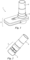
- figure 1 shows a spirometer 1 with a body 2, with which a turbine 3 is associated, in any known manner and detachably.
- a nozzle 4 is connected to the turbine by coupling by means of interference.
- the turbine 3 comprises a main body 5 which can be transparent.
- the body 5 is substantially tubular, and has a through-hole 6.
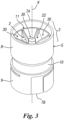
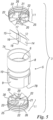
- This tubular body 5 comprises an opening 7A for intake of the air, and an opening 7B for output of the air, and corresponding intake 8 and output 9 portions. Between these, a central portion 10 is present.
- the definitions of intake and output of the turbine are interchangeable, since in the exhalation phase the air travels in one direction, whereas in the inhalation phase, for obvious reasons, the air travels in the opposite direction.
- this rotor has a known form with small blades 14 and 15 facing one another, and projecting orthogonally from a hub 16 which has projections 17 and 18 facing one another, disposed along the axis K and able to rotate in seats 20 of corresponding fulcrums 21 of the deflectors 11.
- Each of these deflectors which are inserted by interference in the respective intake or output portions 8, 9 of the tubular body 5, comprises blades 22 which project from said fulcrum 21, which is placed along a longitudinal axis of the deflector 11 coinciding with the longitudinal axis K of the tubular body 5.
- the blades end at, and are fixed to a cylindrical annular body 25 of the deflector (with a wall 26 lying parallel to the axis K), which body can cooperate in conveying the flow directly together with the internal wall 27 of the corresponding intake or output portion 8, 9 of the tubular body 5.
- the blades 22 are identical to one another, and have the same form; this is in order to avoid irregularities in the flow of air between sectors 30 which are present between said blades (the "gaps" present between the blades), with consequent irregular thrust of the air on the rotor, which thrust, on the contrary, as far as possible, must remain homogenous at any given moment of use of the turbine.
- each of the deflectors has a passive surface and an active surface.
- Active surface means the surface of each blade on which the air flows freely towards the rotor 12 or from the rotor 12.
- Passive surface on the other hand means the surface which opposes the intake of the air into the deflector; in practice this surface is equal to the sum of all the surfaces which do not contribute to the movement of the air within the sectors 30, and which thus do not contribute to the rotation of the air which passes into the deflector, and which ensures the movement of the rotor 12 (and, in the final analysis, operation of the turbine and correct use of the spirometer 1).
- This passive surface is therefore represented by the thickness of end intake portions 35 (with reference to the flow of air) of the blades 22 and by the thickness of the body 25.
- the active surface of the deflector is provided by the sum of all the surfaces of the blades 22, placed between a corresponding end intake edge or portion 35, and an end output edge or portion 36 of said blades, which, when supplied with the air, generate rotary movement thereof which contributes to the rotation of the rotor 12.
- the end edges or portions 35 of the blades 22 are in the interior of the annular body 25 of the deflector 11, whereas the end output portions 36 project from this body.
- the active surface of each blade which is supplied with the air inhaled or exhaled by a patient is defined by a succession of adjacent, consecutive parts with a spatial form which is variable going from the end intake portion 35 to the end output portion 36;
- spatial form which is variable means that the parts which define the active surface have different geometric characteristics; they can be flat or curved surfaces (as will be described hereinafter), which, on any plane X orthogonal to a plane Z which contains the axis K (see fig. 6 , where the plane 7 is orthogonal to the drawing sheet), form a line which converges towards this plane Z.
- the flow of air laps the surface of the blade and follows the configuration thereof, thus according to a path corresponding to the curve shown in figure 6 .
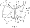
- each blade comprises a first "section of surface” 42 (i.e. a first part of its surface) which is flat and straight in cross-section as schematised in figure 6 , but is inclined with respect to the (cylindrical) wall 26 of the annular body 25 (having generatrices which lie spatially parallel to the longitudinal axis K of the tubular body 5).
- first section of surface 42 From the first section of surface 42 (see figures 8 and 9 ) there extends a second section or part of surface of the blade 43 which is curved (i.e. defined by a curved surface) ending in a third section or part of surface of the blade 44 which is also flat (i.e. defined by a flat surface), but more inclined than the wall 26 of the annular body 25 with respect to the first section of blade 42.
- the third section or part of surface ends in a fourth section or part of surface of the blade 45 which, according to the present invention, is also flat (i.e.
- the fourth section 45 is orthogonal to the plane Z (see fig. 6 ), with the term "orthogonal" meaning an arrangement of the fourth section or part 45 on a plane which forms an angle of 90° with said plane Z, which forms an angle substantially equal to 90° (i.e. at the most equal to 90° ⁇ 5°) taking into consideration the normal construction tolerances associated with production of the deflector 11 by means of moulding of plastic material.
- the fourth section or miniskirt 45 preferably has limited extension along the end output portion 36 of the rotor blade 22, and ends along this portion 36 without reaching the fulcrum 21, in order not to create excessive resistance to the passage of the flow of air inside the deflector.
- the miniskirt affects the air in transit in the turbine 3, creating for the same energy expenditure a normal component of the tangential speed of this air which maximises the thrust in the direction which is incident orthogonally on each small blade 14 or 15 of the rotor.
- This gives rise to reduction of the minimum measurable flow threshold, which is one of the two fundamental objectives for a turbine intended for measurement of spirometry.
- the result is an increase in the performance levels which, for each value of the load, are directly proportional to the maximum tangential speed possible on the mean plane of the rotor.
- the fourth section or miniskirt 45 extends along a part of the output portion 36 of the blade, from the annular body 25 towards the fulcrum 21, so as not to give rise to a significant increase in the resistance to the flow of air, while making it possible to increase the tangential speed of the flow itself.
- the effect of improvement derived from this configuration of the fourth section or miniskirt represents an innovative element which overcomes a technical disadvantage according to which a plane which is placed perpendicularly to the flow of air passing in the deflector from the intake portion 35 to the output portion 36 prevalently results in energy expenditure.
- the solution according to the invention relating to the fact that the plane orthogonal to the flow does not pass along the entire length of the edge of the output portion of the deflector, but only along a part of this portion 36, has made it possible on the contrary to obtain optimum directing of the flow, thus avoiding the additional energy expenditure.
- the section or miniskirt 45 is thus orthogonal (to within the small tolerances of ⁇ 5° determined by the construction methods of the deflector) to the plane Z containing the longitudinal axis K of the deflector, so as to deflect the flow of air orthogonally to this axis K and to the blades 14 and 15.
- each blade 22 has a succession of consecutive, adjacent parts or sections.
- the first section of surface 42 can form an angle ⁇ of between 0.3° and 1.2°, preferably and advantageously between 0.5° and 0.7°, with the wall 26 of the annular body schematised in figure 7 .
- the flat section of surface (or third, straight section) 44 forms an angle ⁇ with a plane P (orthogonal to the planes Z and X) which contains the fourth section 45, of between 37° and 41°, preferably of between 39° and 40° (which corresponds to an angle substantially of between 53° and 49° and 50° and 51° respectively between the extension of this section 44 and the wall 27 of the annular body 25).
- each blade 22 represented by the generatrix curves in figures 6 and 7 ), there is efficient intake (or output) of the air into/from each deflector 11.
- each blade is defined by a succession of sections or parts of surface which are connected to one another with continuity, and which channel and accelerate appropriately the air input into each sector 30 of the deflector 11: the first section of surface or flat section 42 has the function of channelling the air which is accelerated thanks to the combination between said first section of surface and the second curved section of surface 43.
- the remaining sections of surface 44 and 45 make the air flow by directing it directly towards the rotor (substantially following the development of the curve 6 and flowing onto each blade 22).
- the final section of surface or fourth section of blade 45 serves the purpose of maximising the thrust of the flow of air in transit towards the rotor 12 by directing the flow of air orthogonally relative to the small blade, which at a given moment is present at the relative blade 22 of the deflector.
- each blade 22 a direct effect is obtained on the reduction of the minimum measurable flow threshold: the various sections or parts of blade 42-45 give rise to directing of the flow of air onto the rotor which is more efficient than that which can be obtained with the solutions of the prior art, consisting of blades with a surface with a continuous curvature without a final section lying on a plane orthogonal to that which contains the longitudinal axis of the deflector (or of the fulcrum 21 thereof); this form maximises the normal component which is responsible for the thrust on the rotor. This results in a greater thrust for the same load.
- the development of the surface has a direct effect on the minimum measurable flow threshold: the surfaces give rise to more efficient directing of the flow onto the rotor, thus maximising the normal component responsible for the thrust. This therefore results in a greater thrust for the same load. The effect tends to be reduced until it is exhausted when the minimum measurable flow threshold is approached.
- each individual blade 22 can be described by means of a mathematical equation, while being subdivided into four sections of surface, three of which are flat, and one of which is curved.
- the first section of surface 42, the second section 43 and the third section 44 can be generalised by means of a non-linear function of the third order of the coordinate z as a function of the coordinates x and y:
- f x y cost + ax + by + cx 2 + dy 2 + exy + fx 3 + gy 3 + hx 2 + y + ixy 2
Landscapes
- Health & Medical Sciences (AREA)
- Life Sciences & Earth Sciences (AREA)
- Physics & Mathematics (AREA)
- Biomedical Technology (AREA)
- Medical Informatics (AREA)
- Pulmonology (AREA)
- Veterinary Medicine (AREA)
- Biophysics (AREA)
- Pathology (AREA)
- Engineering & Computer Science (AREA)
- Public Health (AREA)
- Heart & Thoracic Surgery (AREA)
- Physiology (AREA)
- Molecular Biology (AREA)
- Surgery (AREA)
- Animal Behavior & Ethology (AREA)
- General Health & Medical Sciences (AREA)
- Fluid Mechanics (AREA)
- General Physics & Mathematics (AREA)
- Structures Of Non-Positive Displacement Pumps (AREA)
- Other Liquid Machine Or Engine Such As Wave Power Use (AREA)
- Measuring Volume Flow (AREA)
- Polyoxymethylene Polymers And Polymers With Carbon-To-Carbon Bonds (AREA)
Claims (8)
- Turbine (3) pour spiromètre (1) comprenant un corps tubulaire creux (5) contenant un rotor (12) mobile autour d'un axe longitudinal (K) de ce corps tubulaire (5) et deux déflecteurs (11) placés à une ouverture d'admission (7A) et à une ouverture de sortie (7B) dudit corps (5), le rotor (12) comprenant de petites pales (14, 15) se faisant face et disposées entre lesdits déflecteurs (11), les déflecteurs comprenant un corps annulaire (25) et un point d'appui (21) disposé le long d'un axe longitudinal de ce corps annulaire (25) coïncidant avec l'axe longitudinal (K) du corps tubulaire (5), entre ledit point d'appui (21) et ledit corps annulaire (25) sont prévues plusieurs pales (22) qui sont solidaires du point d'appui lui-même et du corps annulaire, lesdites pales (22) délimitant une pluralité de secteurs (30) permettant le passage de l'air dirigé vers le rotor, et ayant une partie terminale servant à l'admission de l'air (35) et une partie terminale servant à l'évacuation de l'air (36), chaque pale (22) a un développement continu de la surface qui est défini par une pluralité de sections adjacentes et consécutives de la surface qui ont une forme incurvée et une forme plate, et sont interconnectées les unes aux autres, caractérisées en ce que, à la partie terminale servant à l'évacuation de l'air (36), chaque pale (22) a une section terminale de la surface (45) plate, rectiligne dans toute sa section transversale, ladite section plane étant sur un plan (P) perpendiculaire à l'axe longitudinal (K) dudit corps tubulaire (5) et orthogonal à un plan (Z) contenant ledit axe longitudinal (K), ladite section de surface d'extrémité plane faisant saillie vers la pale adjacente, ladite section de surface d'extrémité (45) étant configurée pour diriger l'air sortant du déflecteur (11) orthogonalement audit plan (Z) contenant l'axe longitudinal (K) du corps tubulaire et orthogonalement sur le rotor (12).
- Turbine selon la revendication 1, caractérisée en ce que les sections adjacentes et consécutives de chaque pale (22) comprennent une section unique définie par une surface incurvée (3).
- Turbine selon la revendication 1, caractérisée en ce qu'il y a quatre (42-45) sections adjacentes et consécutives de la surface de chaque pale (22).
- Turbine selon la revendication 3, caractérisée en ce que, à partir de la partie d'extrémité d'entrée (35) de la pale (22) et jusqu'à la partie d'extrémité d'évacuation (36) de la pale (22), la pale comprend une première section de surface (42) définie par une surface plane, une deuxième section de surface (43) définie par une surface courbe, une troisième section de surface (44) définie par une surface plane, et une quatrième section de surface définissant la section finale de surface (45) reposant sur un plan, la section finale de surface (45) étant inclinée par rapport à la troisième section de surface (44).
- Turbine selon la revendication 4, caractérisée en ce que la première section de la surface (42) forme un angle (β) avec une paroi (26) du corps annulaire (25) compris entre 0,3° et 0,9°, de préférence entre 0,5° et 0,7°.
- Turbine selon la revendication 4, caractérisée en ce que la troisième section de la surface (44) forme un angle (α) par rapport au plan (P) qui contient la section finale de la surface (45) compris entre 37° et 41°, de préférence entre 39° et 40°.
- Turbine selon la revendication 1, caractérisée en ce que la section finale de la surface a une extension limitée le long de la partie d'extrémité d'évacuation (36) de l'air de chaque pale (22).
- Turbine selon la revendication 4, caractérisée en ce que :a) la première section de la surface (42), la deuxième section de la surface (43) et la troisième section de la surface (44) peuvent être définies au moyen d'une fonction non linéaire du troisième ordre de la coordonnée z en fonction des coordonnées x et y :
 b) la section finale de la surface (45) est définie par une fonction linéaire du premier ordre,
Applications Claiming Priority (2)
| Application Number | Priority Date | Filing Date | Title |
|---|---|---|---|
| IT102020000017818A IT202000017818A1 (it) | 2020-07-23 | 2020-07-23 | Turbina per spirometro perfezionata |
| PCT/IB2021/056140 WO2022018555A1 (fr) | 2020-07-23 | 2021-07-08 | Turbine améliorée pour spiromètre |
Publications (3)
| Publication Number | Publication Date |
|---|---|
| EP4185199A1 EP4185199A1 (fr) | 2023-05-31 |
| EP4185199C0 EP4185199C0 (fr) | 2025-03-26 |
| EP4185199B1 true EP4185199B1 (fr) | 2025-03-26 |
Family
ID=72709716
Family Applications (1)
| Application Number | Title | Priority Date | Filing Date |
|---|---|---|---|
| EP21743586.6A Active EP4185199B1 (fr) | 2020-07-23 | 2021-07-08 | Turbine améliorée pour spiromètre |
Country Status (5)
| Country | Link |
|---|---|
| EP (1) | EP4185199B1 (fr) |
| ES (1) | ES3033622T3 (fr) |
| IT (1) | IT202000017818A1 (fr) |
| PL (1) | PL4185199T3 (fr) |
| WO (1) | WO2022018555A1 (fr) |
Families Citing this family (1)
| Publication number | Priority date | Publication date | Assignee | Title |
|---|---|---|---|---|
| IT202100019340A1 (it) * | 2021-07-21 | 2023-01-21 | Mir S R L Medical International Res | Turbina per spirometro con diffusori atti a massimizzare la spinta sul rotore dell'aria espirata o inspirata da un paziente |
Citations (1)
| Publication number | Priority date | Publication date | Assignee | Title |
|---|---|---|---|---|
| CN210494075U (zh) * | 2019-05-24 | 2020-05-12 | 康泰医学系统(秦皇岛)股份有限公司 | 一种肺活量计及其涡轮装置 |
Family Cites Families (6)
| Publication number | Priority date | Publication date | Assignee | Title |
|---|---|---|---|---|
| US3989406A (en) * | 1974-11-26 | 1976-11-02 | Bolt Beranek And Newman, Inc. | Method of and apparatus for preventing leading edge shocks and shock-related noise in transonic and supersonic rotor blades and the like |
| NL8802809A (nl) * | 1988-11-15 | 1990-06-01 | Mijnhardt Bv | Stromingsmeter voor gassen. |
| JP3254191B2 (ja) * | 1999-04-13 | 2002-02-04 | 株式会社フクダ産業 | 呼吸流量・流速計測装置 |
| JP3222855B2 (ja) * | 1999-04-13 | 2001-10-29 | 株式会社フクダ産業 | 呼吸流量・流速計測装置 |
| GB0704426D0 (en) * | 2007-03-08 | 2007-04-18 | Rolls Royce Plc | Aerofoil members for a turbomachine |
| US10939849B2 (en) * | 2018-10-31 | 2021-03-09 | Monitored Therapeutics, Inc | Low flow spirometer turbine |
-
2020
- 2020-07-23 IT IT102020000017818A patent/IT202000017818A1/it unknown
-
2021
- 2021-07-08 WO PCT/IB2021/056140 patent/WO2022018555A1/fr not_active Ceased
- 2021-07-08 EP EP21743586.6A patent/EP4185199B1/fr active Active
- 2021-07-08 ES ES21743586T patent/ES3033622T3/es active Active
- 2021-07-08 PL PL21743586.6T patent/PL4185199T3/pl unknown
Patent Citations (1)
| Publication number | Priority date | Publication date | Assignee | Title |
|---|---|---|---|---|
| CN210494075U (zh) * | 2019-05-24 | 2020-05-12 | 康泰医学系统(秦皇岛)股份有限公司 | 一种肺活量计及其涡轮装置 |
Also Published As
| Publication number | Publication date |
|---|---|
| PL4185199T3 (pl) | 2025-07-14 |
| WO2022018555A1 (fr) | 2022-01-27 |
| EP4185199C0 (fr) | 2025-03-26 |
| IT202000017818A1 (it) | 2022-01-23 |
| ES3033622T3 (en) | 2025-08-06 |
| EP4185199A1 (fr) | 2023-05-31 |
Similar Documents
| Publication | Publication Date | Title |
|---|---|---|
| EP2108927B1 (fr) | Capteur de débit | |
| US10564015B2 (en) | Housing for a flow sensor ventilator including a tubulator and a membrane | |
| FI84757C (fi) | Foer stroemningsmaetning avsett gasens stroemning begraensande och styrande organ. | |
| EP4185199B1 (fr) | Turbine améliorée pour spiromètre | |
| US4441505A (en) | Sensing device for human lung exhalation/inhalation air flow measurement | |
| EP2833789B1 (fr) | Spiromètre | |
| JP2013501570A (ja) | 改良型肺活量計装置及びそれとともに使用するのに有用な方法 | |
| US9999374B2 (en) | Antibacterial filter and turbine flowmeter for tests on respiratory functionality | |
| HK40088030B (en) | Improved turbine for spirometer | |
| HK40088030A (en) | Improved turbine for spirometer | |
| BR112012033642B1 (pt) | Tubo de respiração de espirômetro, membrana composta e uso do tubo | |
| WO2019166804A1 (fr) | Appareil de spirométrie | |
| US10939849B2 (en) | Low flow spirometer turbine | |
| EP3949856B1 (fr) | Dispositif combiné jetable avec filtre antimicrobien et débitmètre destiné à être utilisé en spirométrie | |
| JP3222855B2 (ja) | 呼吸流量・流速計測装置 | |
| JP3594722B2 (ja) | 換気量測定器 | |
| JP6430316B2 (ja) | 流量調整ダンパ | |
| JP6963793B2 (ja) | 呼吸機能検査装置 | |
| Jin et al. | Wearable Applicability of Respiratory Airflow Transducers: Current Approaches and Future Directions | |
| IT202100019340A1 (it) | Turbina per spirometro con diffusori atti a massimizzare la spinta sul rotore dell'aria espirata o inspirata da un paziente | |
| US20130123655A1 (en) | Peak Expiratory Flow Rate Measurement Apparatus | |
| US11821438B2 (en) | Fan unit | |
| JP4004639B2 (ja) | 酸素消費量計 | |
| JPS58169436A (ja) | 呼吸器系の流量測定装置 | |
| Sreeremya et al. | Plethysmography–A Review |
Legal Events
| Date | Code | Title | Description |
|---|---|---|---|
| STAA | Information on the status of an ep patent application or granted ep patent |
Free format text: STATUS: UNKNOWN |
|
| STAA | Information on the status of an ep patent application or granted ep patent |
Free format text: STATUS: THE INTERNATIONAL PUBLICATION HAS BEEN MADE |
|
| PUAI | Public reference made under article 153(3) epc to a published international application that has entered the european phase |
Free format text: ORIGINAL CODE: 0009012 |
|
| STAA | Information on the status of an ep patent application or granted ep patent |
Free format text: STATUS: REQUEST FOR EXAMINATION WAS MADE |
|
| 17P | Request for examination filed |
Effective date: 20230203 |
|
| AK | Designated contracting states |
Kind code of ref document: A1 Designated state(s): AL AT BE BG CH CY CZ DE DK EE ES FI FR GB GR HR HU IE IS IT LI LT LU LV MC MK MT NL NO PL PT RO RS SE SI SK SM TR |
|
| RAP3 | Party data changed (applicant data changed or rights of an application transferred) |
Owner name: MIR - MEDICAL INTERNATIONAL RESEARCH S.P.A. |
|
| REG | Reference to a national code |
Ref country code: HK Ref legal event code: DE Ref document number: 40088030 Country of ref document: HK |
|
| DAV | Request for validation of the european patent (deleted) | ||
| DAX | Request for extension of the european patent (deleted) | ||
| GRAP | Despatch of communication of intention to grant a patent |
Free format text: ORIGINAL CODE: EPIDOSNIGR1 |
|
| STAA | Information on the status of an ep patent application or granted ep patent |
Free format text: STATUS: GRANT OF PATENT IS INTENDED |
|
| INTG | Intention to grant announced |
Effective date: 20241212 |
|
| GRAS | Grant fee paid |
Free format text: ORIGINAL CODE: EPIDOSNIGR3 |
|
| GRAA | (expected) grant |
Free format text: ORIGINAL CODE: 0009210 |
|
| STAA | Information on the status of an ep patent application or granted ep patent |
Free format text: STATUS: THE PATENT HAS BEEN GRANTED |
|
| AK | Designated contracting states |
Kind code of ref document: B1 Designated state(s): AL AT BE BG CH CY CZ DE DK EE ES FI FR GB GR HR HU IE IS IT LI LT LU LV MC MK MT NL NO PL PT RO RS SE SI SK SM TR |
|
| REG | Reference to a national code |
Ref country code: GB Ref legal event code: FG4D |
|
| REG | Reference to a national code |
Ref country code: CH Ref legal event code: EP |
|
| REG | Reference to a national code |
Ref country code: DE Ref legal event code: R096 Ref document number: 602021028172 Country of ref document: DE |
|
| REG | Reference to a national code |
Ref country code: IE Ref legal event code: FG4D |
|
| U01 | Request for unitary effect filed |
Effective date: 20250418 |
|
| U07 | Unitary effect registered |
Designated state(s): AT BE BG DE DK EE FI FR IT LT LU LV MT NL PT RO SE SI Effective date: 20250428 |
|
| U20 | Renewal fee for the european patent with unitary effect paid |
Year of fee payment: 5 Effective date: 20250507 |
|
| PG25 | Lapsed in a contracting state [announced via postgrant information from national office to epo] |
Ref country code: RS Free format text: LAPSE BECAUSE OF FAILURE TO SUBMIT A TRANSLATION OF THE DESCRIPTION OR TO PAY THE FEE WITHIN THE PRESCRIBED TIME-LIMIT Effective date: 20250626 |
|
| PGFP | Annual fee paid to national office [announced via postgrant information from national office to epo] |
Ref country code: PL Payment date: 20250509 Year of fee payment: 5 |
|
| PG25 | Lapsed in a contracting state [announced via postgrant information from national office to epo] |
Ref country code: NO Free format text: LAPSE BECAUSE OF FAILURE TO SUBMIT A TRANSLATION OF THE DESCRIPTION OR TO PAY THE FEE WITHIN THE PRESCRIBED TIME-LIMIT Effective date: 20250626 |
|
| PG25 | Lapsed in a contracting state [announced via postgrant information from national office to epo] |
Ref country code: HR Free format text: LAPSE BECAUSE OF FAILURE TO SUBMIT A TRANSLATION OF THE DESCRIPTION OR TO PAY THE FEE WITHIN THE PRESCRIBED TIME-LIMIT Effective date: 20250326 |
|
| PG25 | Lapsed in a contracting state [announced via postgrant information from national office to epo] |
Ref country code: GR Free format text: LAPSE BECAUSE OF FAILURE TO SUBMIT A TRANSLATION OF THE DESCRIPTION OR TO PAY THE FEE WITHIN THE PRESCRIBED TIME-LIMIT Effective date: 20250627 |
|
| PGFP | Annual fee paid to national office [announced via postgrant information from national office to epo] |
Ref country code: TR Payment date: 20250630 Year of fee payment: 5 |
|
| PGFP | Annual fee paid to national office [announced via postgrant information from national office to epo] |
Ref country code: CZ Payment date: 20250613 Year of fee payment: 5 |
|
| REG | Reference to a national code |
Ref country code: ES Ref legal event code: FG2A Ref document number: 3033622 Country of ref document: ES Kind code of ref document: T3 Effective date: 20250806 |
|
| REG | Reference to a national code |
Ref country code: SK Ref legal event code: T3 Ref document number: E 46591 Country of ref document: SK |
|
| PG25 | Lapsed in a contracting state [announced via postgrant information from national office to epo] |
Ref country code: SM Free format text: LAPSE BECAUSE OF FAILURE TO SUBMIT A TRANSLATION OF THE DESCRIPTION OR TO PAY THE FEE WITHIN THE PRESCRIBED TIME-LIMIT Effective date: 20250326 |
|
| PGFP | Annual fee paid to national office [announced via postgrant information from national office to epo] |
Ref country code: ES Payment date: 20250805 Year of fee payment: 5 |
|
| PGFP | Annual fee paid to national office [announced via postgrant information from national office to epo] |
Ref country code: GB Payment date: 20250728 Year of fee payment: 5 |
|
| PGFP | Annual fee paid to national office [announced via postgrant information from national office to epo] |
Ref country code: SK Payment date: 20250526 Year of fee payment: 5 |
|
| PG25 | Lapsed in a contracting state [announced via postgrant information from national office to epo] |
Ref country code: IS Free format text: LAPSE BECAUSE OF FAILURE TO SUBMIT A TRANSLATION OF THE DESCRIPTION OR TO PAY THE FEE WITHIN THE PRESCRIBED TIME-LIMIT Effective date: 20250726 |
|
| REG | Reference to a national code |
Ref country code: CH Ref legal event code: U11 Free format text: ST27 STATUS EVENT CODE: U-0-0-U10-U11 (AS PROVIDED BY THE NATIONAL OFFICE) Effective date: 20251031 |
|
| PGFP | Annual fee paid to national office [announced via postgrant information from national office to epo] |
Ref country code: CH Payment date: 20251031 Year of fee payment: 5 |
|
| PLBE | No opposition filed within time limit |
Free format text: ORIGINAL CODE: 0009261 |
|
| STAA | Information on the status of an ep patent application or granted ep patent |
Free format text: STATUS: NO OPPOSITION FILED WITHIN TIME LIMIT |
|
| REG | Reference to a national code |
Ref country code: CH Ref legal event code: L10 Free format text: ST27 STATUS EVENT CODE: U-0-0-L10-L00 (AS PROVIDED BY THE NATIONAL OFFICE) Effective date: 20260211 |
|
| 26N | No opposition filed |
Effective date: 20260105 |