EP4185759B1 - 3d-verstellbares verborgenes scharnier für bündige oder gefalzte tür- oder fensteranwendungen - Google Patents
3d-verstellbares verborgenes scharnier für bündige oder gefalzte tür- oder fensteranwendungen Download PDFInfo
- Publication number
- EP4185759B1 EP4185759B1 EP21807238.7A EP21807238A EP4185759B1 EP 4185759 B1 EP4185759 B1 EP 4185759B1 EP 21807238 A EP21807238 A EP 21807238A EP 4185759 B1 EP4185759 B1 EP 4185759B1
- Authority
- EP
- European Patent Office
- Prior art keywords
- sash
- arm
- lever
- translational
- frame
- Prior art date
- Legal status (The legal status is an assumption and is not a legal conclusion. Google has not performed a legal analysis and makes no representation as to the accuracy of the status listed.)
- Active
Links
Images








Classifications
-
- E—FIXED CONSTRUCTIONS
- E05—LOCKS; KEYS; WINDOW OR DOOR FITTINGS; SAFES
- E05D—HINGES OR SUSPENSION DEVICES FOR DOORS, WINDOWS OR WINGS
- E05D3/00—Hinges with pins
- E05D3/06—Hinges with pins with two or more pins
- E05D3/18—Hinges with pins with two or more pins with sliding pins or guides
-
- E—FIXED CONSTRUCTIONS
- E05—LOCKS; KEYS; WINDOW OR DOOR FITTINGS; SAFES
- E05D—HINGES OR SUSPENSION DEVICES FOR DOORS, WINDOWS OR WINGS
- E05D3/00—Hinges with pins
- E05D3/06—Hinges with pins with two or more pins
- E05D3/18—Hinges with pins with two or more pins with sliding pins or guides
- E05D3/186—Scissors hinges, with two crossing levers and five parallel pins
-
- E—FIXED CONSTRUCTIONS
- E05—LOCKS; KEYS; WINDOW OR DOOR FITTINGS; SAFES
- E05D—HINGES OR SUSPENSION DEVICES FOR DOORS, WINDOWS OR WINGS
- E05D7/00—Hinges or pivots of special construction
- E05D7/04—Hinges adjustable relative to the wing or the frame
-
- E—FIXED CONSTRUCTIONS
- E05—LOCKS; KEYS; WINDOW OR DOOR FITTINGS; SAFES
- E05D—HINGES OR SUSPENSION DEVICES FOR DOORS, WINDOWS OR WINGS
- E05D7/00—Hinges or pivots of special construction
- E05D7/04—Hinges adjustable relative to the wing or the frame
- E05D2007/0461—Hinges adjustable relative to the wing or the frame in angular arrangement to the wing or the frame
-
- E—FIXED CONSTRUCTIONS
- E05—LOCKS; KEYS; WINDOW OR DOOR FITTINGS; SAFES
- E05D—HINGES OR SUSPENSION DEVICES FOR DOORS, WINDOWS OR WINGS
- E05D7/00—Hinges or pivots of special construction
- E05D7/04—Hinges adjustable relative to the wing or the frame
- E05D2007/0476—Pocket hinges
-
- E—FIXED CONSTRUCTIONS
- E05—LOCKS; KEYS; WINDOW OR DOOR FITTINGS; SAFES
- E05D—HINGES OR SUSPENSION DEVICES FOR DOORS, WINDOWS OR WINGS
- E05D7/00—Hinges or pivots of special construction
- E05D7/04—Hinges adjustable relative to the wing or the frame
- E05D2007/0484—Hinges adjustable relative to the wing or the frame in a radial direction
-
- E—FIXED CONSTRUCTIONS
- E05—LOCKS; KEYS; WINDOW OR DOOR FITTINGS; SAFES
- E05Y—INDEXING SCHEME ASSOCIATED WITH SUBCLASSES E05D AND E05F, RELATING TO CONSTRUCTION ELEMENTS, ELECTRIC CONTROL, POWER SUPPLY, POWER SIGNAL OR TRANSMISSION, USER INTERFACES, MOUNTING OR COUPLING, DETAILS, ACCESSORIES, AUXILIARY OPERATIONS NOT OTHERWISE PROVIDED FOR, APPLICATION THEREOF
- E05Y2600/00—Mounting or coupling arrangements for elements provided for in this subclass
- E05Y2600/10—Adjustable
- E05Y2600/30—Adjustment motion
- E05Y2600/31—Linear motion
-
- E—FIXED CONSTRUCTIONS
- E05—LOCKS; KEYS; WINDOW OR DOOR FITTINGS; SAFES
- E05Y—INDEXING SCHEME ASSOCIATED WITH SUBCLASSES E05D AND E05F, RELATING TO CONSTRUCTION ELEMENTS, ELECTRIC CONTROL, POWER SUPPLY, POWER SIGNAL OR TRANSMISSION, USER INTERFACES, MOUNTING OR COUPLING, DETAILS, ACCESSORIES, AUXILIARY OPERATIONS NOT OTHERWISE PROVIDED FOR, APPLICATION THEREOF
- E05Y2600/00—Mounting or coupling arrangements for elements provided for in this subclass
- E05Y2600/10—Adjustable
- E05Y2600/30—Adjustment motion
- E05Y2600/31—Linear motion
- E05Y2600/312—Horizontal motion
-
- E—FIXED CONSTRUCTIONS
- E05—LOCKS; KEYS; WINDOW OR DOOR FITTINGS; SAFES
- E05Y—INDEXING SCHEME ASSOCIATED WITH SUBCLASSES E05D AND E05F, RELATING TO CONSTRUCTION ELEMENTS, ELECTRIC CONTROL, POWER SUPPLY, POWER SIGNAL OR TRANSMISSION, USER INTERFACES, MOUNTING OR COUPLING, DETAILS, ACCESSORIES, AUXILIARY OPERATIONS NOT OTHERWISE PROVIDED FOR, APPLICATION THEREOF
- E05Y2600/00—Mounting or coupling arrangements for elements provided for in this subclass
- E05Y2600/40—Mounting location; Visibility of the elements
- E05Y2600/41—Concealed
-
- E—FIXED CONSTRUCTIONS
- E05—LOCKS; KEYS; WINDOW OR DOOR FITTINGS; SAFES
- E05Y—INDEXING SCHEME ASSOCIATED WITH SUBCLASSES E05D AND E05F, RELATING TO CONSTRUCTION ELEMENTS, ELECTRIC CONTROL, POWER SUPPLY, POWER SIGNAL OR TRANSMISSION, USER INTERFACES, MOUNTING OR COUPLING, DETAILS, ACCESSORIES, AUXILIARY OPERATIONS NOT OTHERWISE PROVIDED FOR, APPLICATION THEREOF
- E05Y2900/00—Application of doors, windows, wings or fittings thereof
- E05Y2900/10—Application of doors, windows, wings or fittings thereof for buildings or parts thereof
- E05Y2900/13—Type of wing
- E05Y2900/132—Doors
-
- E—FIXED CONSTRUCTIONS
- E05—LOCKS; KEYS; WINDOW OR DOOR FITTINGS; SAFES
- E05Y—INDEXING SCHEME ASSOCIATED WITH SUBCLASSES E05D AND E05F, RELATING TO CONSTRUCTION ELEMENTS, ELECTRIC CONTROL, POWER SUPPLY, POWER SIGNAL OR TRANSMISSION, USER INTERFACES, MOUNTING OR COUPLING, DETAILS, ACCESSORIES, AUXILIARY OPERATIONS NOT OTHERWISE PROVIDED FOR, APPLICATION THEREOF
- E05Y2900/00—Application of doors, windows, wings or fittings thereof
- E05Y2900/10—Application of doors, windows, wings or fittings thereof for buildings or parts thereof
- E05Y2900/13—Type of wing
- E05Y2900/148—Windows
Definitions
- the present invention relates to a door or window hinge, and more particularly to a hidden or invisible hinge that can be used for both flush or rebated door or window applications.
- Hidden hinges are known for mounting either a door or sash to a frame.
- different types of hinges are typically used for mounting rebated doors or sashes in comparison to flush mounted doors or sashes. This is due to the overlapping edge of the rebated door or sash which has to be accounted for in the hinge movement in order to lift this off and away from the frame, while at the same time moving it back from the opening so that this overlapping edge is moved away from the clear opening in the frame.
- hinges also allow for adjustment in 3 directions in a simple and convenient manner such that a precise side-to-side and up-and-down alignment of the door panel or sash parallel to the corresponding frame can be achieved for proper positioning as well as an in-and-out adjustment for proper sealing.
- the hinge includes a frame part adapted to be fixed to the frame, that has a frame mounting part having a cavity, a frame body mounted in the cavity, with the frame body including a first recess and a second recess.
- the hinge further includes a door or sash part adapted to be fixed to the door or sash, that has a movable door or sash mounting part, a sash body connected to the movable door or sash mounting part, and a sash movable body slidably mounted by a slidable mounting arrangement on the sash body, the sash movable body including a first recess and a second recess.
- a rotational lever-arm system is connected between the frame body and the sash movable body that is at least partially located in the first recesses of the frame body and the sash movable body.
- frame body and sash movable body may be replaced by the acronyms FB and SMB respectively.
- the rotational lever-arm system includes a frame lever-arm including a FB side and a SMB side and a medial position located at a point between the FB side and the SMB side, and a sash lever-arm including a FB side and a SMB side and a medial position located at a point between the FB side and the SMB side of the sash lever-arm.
- a rotational pin connects the frame lever-arm at the frame lever-arm medial position to the sash lever-arm at the sash lever-arm medial position for pivoting movement.
- a first rotational arm pin pivotally connects the SMB side of the frame lever-arm to the sash movable body.
- a second rotational arm pin pivotally connects the FB side of the sash lever-arm to the frame body.
- a FB guide projection on the FB side of the frame lever-arm is received in a FB rotation guide groove in the first recess of the frame body, and a SMB guide projection on the SMB side of the sash lever-arm is received in a SMB rotation guide groove in the first recess of the sash movable body.
- a first translational arm system is also connected between the frame body, the movable sash body, and the sash body, with the first translational arm system being at least partially located in the second recesses of the frame body and the sash movable body and including a translational first lever-arm having a first end and a second end, a translational second lever-arm having a FB side and a SB side, with a translational FB guide projection located on the FB side of the translational second lever-arm.
- a translational first lever-arm pivot connection point is located between the FB side and the SB side of the translational second lever-arm, and a sash body pivot connection point is located at the SB side.
- a first translational pin pivotably connects the first end of the translational first lever-arm to the translational first lever-arm pivot connection point on the translational second lever-arm.
- a second translational pin pivotably connects the second end of the translational first lever-arm to the sash movable body.
- a third translational pin pivotably connects the sash body pivot connection point of the translational second lever-arm to the sash body.
- the translational guide projection on the FB side of the translational second lever-arm is received in a translational guide groove in the second recess of the frame body.
- the first, second, and third translational pins and the first and second rotational arm pins extend along axes that are parallel to one another.
- the sash body is preferably adjustably connected to the movable door or sash mounting part to allow for relative movement that is adapted to adjust a gasket pressure of a movable door or sash connected to a frame by the hinge.
- the sash movable body includes a third recess, and the first recess of the sash movable body is located between the second and third recesses of the sash movable body.
- the frame body includes a third recess, and the first recess of the frame body is located the second and third recesses of the frame body, and the first, second, and third recesses of the sash movable body being aligned respectively with the first, second, and third recesses of the frame body.
- a second translational arm system is connected between the frame body, the sash movable body and the sash body, and the second translational arm system is at least partially located in the third recesses of the frame body and the sash movable body.
- the second translational arm system is identical to the first translational arm system.
- the slidable mount of the sash movable body on the sash body is formed by first and second posts on the sash body that extend parallel to one another into first and second channels that are defined through a base of the sash movable body with a sliding fit, and extend into the second and third recesses.
- the first and second posts include post pivot attachment ends that extend into the second and third recesses, and the third translational pin of each of the first and second translational arm systems are connected respectively to the sash body at the post pivot attachment ends of the first and second posts.
- the hinge is movable from a closed position, in which the sash body and the frame body are generally aligned with one another, the sash movable body being in an inserted position in the sash body, and the first, second, and third recesses of the sash movable body and the first, second, and third recesses of the frame being aligned with and facing one another with the rotational lever-arm system and the first and second translational arm systems located in the respective sets of the first, second, and third recesses of the sash movable body and the frame body, to an open position, in which the sash body and the frame body are adjacent to one another, the sash movable body is moved to an extended position out from the sash body, and the frame and sash lever-arms as well as the translational second lever-arms are extended from the respective recesses.
- This provides for a hinge arrangement that can either be used in rebated or flush mount applications.
- movement of the hinge toward the open position causes the translational first lever-arms acting on the sash movable body in conjunction with movement of the translational second lever-arms that pivot about the third translational pins that connect the sash body pivot connection points of the translational second lever-arms to the sash body, to move the sash movable body to the extended position.
- the FB guide projections there are two of the FB guide projections located on opposite edges of the FB side of the frame lever-arm and there are two of the FB rotation guide grooves located in opposite walls of the first recess of the frame body, with each of the FB guide projections being located in a respective one of the FB rotation guide grooves.
- the FB rotation guide grooves extend generally linearly, parallel to one another in the opposite walls of the first recess of the frame body.
- the term generally refers to +/-10% of a value, or +/- 10 degrees of an angle. With respect to a linear path, variations within a range of +/- 2 mm of an ideal line are permitted.
- the SMB guide projections located on opposite edges of the SMB side of the sash lever-arm and there are two of the SMB rotation guide grooves located in opposite walls of the first recess of the sash movable body, with each of the SMB guide projections being located in a respective one of the SMB rotation guide grooves.
- the SMB guide grooves extend generally linearly, parallel to one another in the opposite walls of the first recess of the sash movable body.
- the translational guide projections located on opposite edges of the FB side of the translational second lever-arm and there are two of the translational guide grooves on opposite walls of the second recess, with each of the translational guide projections being located in a respective one of the translational guide grooves.
- the translational guide grooves extend parallel to one another with a curved path in the opposite walls of the second recess.
- the frame body is adjustably mounted in the frame mounting part. This preferably allows for both up-and-down as well as side-to-side adjustment for centering of the sash or door in the frame.
- the frame lever-arm includes a slot between the FB side and the SMB side, the sash lever-arm extends through the slot, and the connection of the frame lever-arm at the frame lever-arm medial position to the sash lever-arm at the sash lever-arm medial position is in an area of the slot.
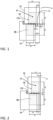
- FIG. 1 shows a hinge 10 for mounting a door or window sash 12 to a frame 14 with two different mounting configurations for the same hinge 10.
- Figure 1 shows a rebated mount in which the door or window sash 12 includes a lip 13 that overlaps the frame 14 in the closed position.
- Figure 2 shows a flush mount in which the door or window sash 12 sits flush with the frame 14 when the hinge 10 is in the closed position.
- An optional gasket 155 is shown between the door or window sash 12 and the frame 14. However, this could be omitted. It is noted that the dimensions in Figures 1 and 2 are exemplary and could be changed depending on the particular application.
- FIGS 3-6 show the hinge 10 fully assembled.
- the hinge 10 includes a frame part 20 that is adapted to be fixed to the frame 14 as well as a door or sash part 40 that is adapted to be fixed to the door or sash 12. These are connected by a rotational lever-arm system 80 as well as at least a first translational arm system 110. In a preferred arrangement a second translation arm system 110' is also provided that is connected between the frame part 20 and the door or sash part 40.
- Figure 4 shows the hinge 10 in the open position while Figure 5 shows the hinge 10 in the closed position.
- Figure 6 shows the hinge 10 in a partially open position.
- the frame part 20 includes a frame mounting part 22 having a cavity 24 as well as a frame body 30 that is mounted in the cavity 24.
- the frame body 30 includes a first recess 32A as well as a second recess 32B.
- a third recess 32C is also provided however, this is optional.
- the door sash part 40 includes a moveable door sash part 42 as well as a sash body 50 that is connected to the moveable door or sash part 42.
- a sash movable body 60 is slidably mounted, preferably by sliding mount arrangements 65 best shown in Figs. 14 and 18 - 20 , on the sash body 50.
- the sash moveable body 60 includes a first recess 62A and a second recess 62B. In a preferred arrangement, a third recess 62C is also provided on the sash moveable body 60.
- the rotational lever-arm system 80 is preferably arranged in the first recess 32A of the frame body 30 and the first recess 62A of the sash movable body 60.
- the first translational arm system 110 is preferably located in the second recess 32B of the frame body 30 as well as in the second recess 62B of the sash moveable body 60.
- the second translational arm system 110' is preferably arranged in the third recess 32C of the frame body 30 and the third recess 62C of the sash moveable body 60.
- the rotational lever-arm system 80 that is connected between the frame body 30 and the sash movable body 60 is described in detail.
- the rotational lever-arm system 80 provides for supported and guided rotational movement of the door or sash part 40 180° such that the door or sash part 40 is moved from a closed position which is generally aligned with the frame body 30, shown in Fig. 9 , into an open position in which it is spaced apart from but adjacent to the frame body 30, shown in Fig. 11 .
- the rotational lever-arm system 80 is at least partially, and preferably almost entirely, located within the first recesses 32A, 62A of the frame body 30 and the sash moveable body 60, as shown in Figure 9
- the rotational lever-arm system 80 includes a frame lever-arm 82, shown in detail in Figures 12 and 13 , that includes a FB side 83 and an SMB side 84 as well as a medial position 85 located at a point between the FB side 83 and the SMB side 84.
- the rotational lever-arm system 80 further includes a sash lever-arm 90 including a FB side 91 and an SMB side 92 as well as a medial position 93 located at a point between the FB side 91 and the SMB side 92 of the sash lever-arm 90 is also provided.
- a rotational pin 98 connects the frame lever arm 82 at the frame lever-arm medial position 85 to the sash lever-arm 90 at the sash lever-arm medial position 93 for pivoting movement.
- the frame lever-arm 82 includes a slot 88 between the FB side 83 and the SMB side 84, and the sash lever-arm 90 extends through the slot 88.
- the connection of the frame lever-arm 82 at the frame lever-arm medial position 85 to the sash lever-arm 90 at the sash lever-arm medial position 93 is in an area of this slot 88, as shown in detail in Figure 12 .
- a first rotational arm pin 99 pivotally connects the SMB side 84 of the frame lever-arm 82 to the sash moveable body 60.
- a second rotational arm pin 100 pivotally connects the FB side 91 of the sash lever-arm 90 to the frame body 30. The locations of these first and second rotational arm pins 99 and 100 can be seen more clearly in Figure 32 from the underside of the hinge 10.
- a FB guide projection 86A is located on the FB side 83 of the frame lever-arm 82 that is received in a FB guide groove 34A in the first recess 32A of the frame body 30.
- Each of the FB guide projections 86A, 86B is located in a respective one of the FB guide grooves 34A, 34B.
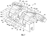
- the FB guide grooves 34A, 34B extend generally linearly, parallel to one another in the opposite walls 35, 36 of the first recess 32A of the frame body 30. As shown in Figures 7 and 13 , the groove is lower at a position away from the door or sash part 40 when in the open position and extends to a higher position at the side adjacent to the door sash part 40 in the open position.
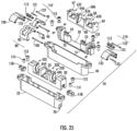
- the FB guide projections 86A, 86B may be integral with the frame lever-arm 82 as shown in Figures 12 and 25 . It is also possible to form the FB guide projections 86A', 86B' as separate inserts formed of a plastic bearing material, such as a polyamide, that are pressed into corresponding openings in the frame lever-arm 82', as shown in Figures 34 - 36 , which can be used in the same manner as the frame lever-arm 82.
- the plastic bearing material can provide for smoother travel in the FB guide grooves 34A, 34B and longer wear.
- plastic bearings 101 for example made of a polyamide, can also be pressed into openings in the SMB side 84 of the frame lever-arm 82, 82' where the first rotational arm pin 99 is inserted to provide for smoother movement and increased wear.
- a SMB guide projection 94A is located on the SMB side 92 of the sash lever-arm 90 that is received in a SMB rotation guide groove 64A in the first recess 62A of the sash moveable body 60.
- Each of the SMB guide projections 94A, 94B is located in a respective one of the SMB rotation guide grooves 64A, 64B.
- the SMB guide projections 94A, 94B may be integral with the sash lever-arm 90 as shown in Figures 12 and 25 . It is also possible to form the SMB guide projections 94A', 94B' as separate inserts formed of a plastic bearing material, such as a polyamide, that are pressed into corresponding openings in the sash lever-arm 90', as shown in Figures 34 , 37, and 38 , which can be used in the same manner as the sash lever-arm 90.
- the plastic bearing material can provide for smoother travel in the SMB rotation guide grooves 64A, 64B and longer wear.
- plastic bearings 102 for example made of a polyamide, can also be pressed into openings in the FB side 84 of the sash lever-arm 90, 90' where the second rotational arm pin 100 is inserted as well as at the location for the rotational pin 98 to provide for smoother movement and increased wear.
- the SMB guide grooves 64A, 64B extend generally linearly, parallel to one another in the opposite side wall 69A, 69B of the first recess 62A of the sash movable body 60. As best seen in Figures 19 and 25 , these SMB guide grooves 64A, 64B extend generally upwardly from the base 68 of the sash moveable body 60 toward an upper surface of the sash movable body 60.
- the movement provided by the rotational lever-arm system 80 between the frame part 20 and the door or sash part 40 is a controlled rotation of 180° as shown in Figures 9-11 that is constrained by the first and second rotational arm pins 99, 100 as well as the FB guide projection 86A sliding in the FB rotation guide groove 34A and the SMB guide projection 94A sliding in the SMB rotation guide groove 64A while the frame lever-arm 82 and the sash lever-arm 90 pivot relative one another about the rotational pin 98.
- the first translation arm system 110 is connected between the frame body 30, the moveable sash body 60, and the sash body 50. As shown in Figure 15 , when the hinge 10 is in the closed position, the first translation arm system 110 is at least partially, and preferably mostly, located in the second recesses 32B, 62B of the frame body 30 and the sash moveable body 60.
- the first translational arm system 110 includes a first translational arm lever-arm 112 having a first end 113 and a second end 114.
- a translational second lever-arm 120 is provided having an FB side 121 and an SB side 122.
- a translational FB guide projection 124A in located on the FB side 121 of the translational second lever-arm 120.
- first and second FB guide projections 124A, 124B are located on opposite edges of the FB side 121 of the translation second lever-arm 120.
- a translational first lever-arm pivot connection point 126 is located between the FB side 121 and the SB side 122 side of the translational second lever-arm 120.
- a sash body pivot connection point 128 is located at the SB side 122.
- a first translational pin 131 pivotally connects the first end 113 of the translation first lever-arm 112 to the translational first lever-arm pivot connection point 126 on the translational second lever-arm 120 and forms the pivot between the translational first and second lever-arms 112, 120.
- a second translational pin 132 pivotally connects the second end 114 of the translational first lever-arm 112 to the sash movable body 60.
- a third translational pin 133 pivotally connects the sash body pivot connection point 128 of the translational second lever-arm 120 to the sash body 50.
- the translational guide projection 124A on the FB side of the second lever-arm 120 is received in a translational guide groove 44A in the second recess 32B of the frame body 30.
- each of the translational guide projections 124A, 124B is located in a respective one of the translational guide grooves 44A, 44B.
- the translational guide grooves 44A, 44B extend parallel to one another with a curved path in the opposite walls 37, 38 of the second recess 32B.
- the FB guide projections 124A, 124B may be integral with the translational second lever-arm 120 or held in place via a pin as shown in Figures 18 , 19 , and 25 . It is also possible to form the FB guide projections 124A', 124B' as separate inserts formed of a plastic bearing material, such as a polyamide, that are pressed into corresponding openings in the translational second lever-arm 120', as shown in Figures 34 and 39 , which can be used in the same manner as the translational second lever-arm 120.
- the plastic bearing material can provide for smoother travel in the translational guide grooves 44A, 44B and longer wear.
- plastic bearings 103 can also be pressed into openings located at the translational first lever-arm pivot connection point 126 in the translational second lever-arm 120, 120' where the first translational pin 131 is inserted as well as at the sash body pivot connection point 128 of the translational second lever-arm 120, 120' where the third translational pin 133 is inserted to provide for smoother movement and increased wear.
- This arrangement of the first translational arm system acts in conjunction with the controlled rotational movement provided by the rotational lever-arm system 80 in order to extend the sash moveable body 60 from the sash body 50 as the hinge 10 moves from the closed position shown in Figure 15 to the open position as shown in Figure 17 .
- This translational movement is created by the translational first lever-arm 112 acting as a lever to slide the sash moveable body 60 apart from the sash body 50 based on the movement provided by the translational second lever-arm 120 being pulled from its closed position when the hinge 10 is moved from the closed position to the open position.
- the sash moveable body 60 includes the third recess 62C, and the first recess 62A of the sash moveable body 60 is located between the second recess 62B and the third recess 62C of the sash movable body 60.
- the frame body 30 also includes the third recess 32C and the first recess 32A of the frame body 30 is located between the second recess 32B and the third recess 32C of the frame body 30.
- the first, second, and third recesses 62A - C of the sash moveable body 60 are aligned respectively with the first, second, and third recesses 32A, 32C of the frame body 30.
- a second translational arm system 110' is connected between the frame body 30, the sash moveable body 60, and the sash body 50.
- the second translational arm system 110' is at least partially located in the third recesses 32C, 62C of the frame body 30 and the sash movable body 60.
- the second translational arm system 110' is identical to the first translational arm system 110 and like parts are indicated with the same reference numbers in the drawings.
- the frame body 30 includes translational guide grooves 44A', 44B' in the opposite walls 45, 46 of the third recess 32C which received the translational guide projections 124A, 124B on the FB side of the translational second lever-arm 120 of the second translational arm system 110'.
- the slidable mounting arrangement 65 between the sash movable body 60 and the sash body 50 is preferably formed by first and second posts 51, 52 on the sash body 50 that extend parallel to one another into first and second channels 66, 67 defined through the base 68 of the sash movable body with a sliding fit. This is best illustrated in Figures 14 , 26 , and 28 .
- the first and second post 51, 52 include post pivot attachment ends 53, 54 that extend into the second and third recesses 62B, 62C of the sash movable body 60, and the third translational pin 133 of each of the first and second translational arm systems 110, 110' are connected respectively to the sash body 50 at the post pivot attachment ends 53, 54 of the first and second post 51, 52.
- This arrangement provides for a smooth sliding movement between the sash movable body 60 and the sash body 50 during the translational movement of the hinge 10.
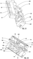
- the hinge 10 is movable from a closed position in which the sash body 50 and the frame body 30 are generally aligned with one another, as shown in Figure 5 (as well as Figs. 40 and 41 ), with the sash movable body 60 being in an inserted position in the sash body 50, shown in Figure 15 and Figures 32 , and the first, second, and third recesses 62A - C of the sash moveable body 60 and the first, second, and third recesses 32A - C of the frame 30 are aligned with and facing one another, with the rotational lever-arm system 80 and the first and second translational arm systems 110, 110' being located in the respective first, second, and third recesses, 32A - C; 62A - C of the frame body 30 and the sash movable body 60, to an open position, in which the sash body 50 and the frame body 30 are adjacent to one another, shown in Figure 4 , with the sash movable body 60 being moved to an extended position
- first, second, and third translational pins 131, 132, 133, as well as the second rotational arm pins 99, 100 extend along the axes that are parallel to one another.
- the frame body 30 is adjustably mounted in the frame mounting part 24.
- this is accomplished via adjuster screws.
- the adjuster screws 151 shown in Figures 21 and 24 allow for inward and outward movement of the frame body 30 relative to the frame mounting part 24 which effects a side-to-side (horizontal) movement of the door or window sash 12 for adjustment purposes.
- Adjustment of the adjustment screws 152 shown in Figure 22 and Figure 24 allows for an up-or-down movement of the frame body 30 relative to the frame mounting part 22, which is accomplished by the adjuster screws 152 moving up or down the inclined surfaces on parts 158 shown in detail in Figures 25 and 26 in order to effect the desired movement up or down.
- the sash body 50 is adjustably connected to the movable door sash mounting part 42 to allow for a relative movement that is adapted to adjust a gasket pressure of a movable door sash 12 connected to a frame 14 by the hinge 10. This is accomplished by adjuster screws 153 shown in Figs. 23 and 24 , that include an eccentric connected between the sash body 50 and the movable door or sash mounting part 42 in order to provide for inward or outward movement of the door or window sash 12 in the closed position in order to effect more or less pressure against the gasket 155 shown in Figures 1 and 2 .
Landscapes
- Engineering & Computer Science (AREA)
- Mechanical Engineering (AREA)
- Hinges (AREA)
Claims (15)
- Scharnier zur Befestigung eines Tür- oder Fensterflügels an einem Rahmen, wobei das Scharnier (10) Folgendes umfasst:ein Rahmenteil (20), das an dem Rahmen (14) befestigt werden kann, wobei das Rahmenteil umfasst:ein Rahmenbefestigungsteil (22) mit einem Hohlraum (24),einen Rahmenkörper (FB, 30), der in dem Hohlraum (24) montiert ist,wobei der Rahmenkörper (30) eine erste Ausnehmung(32A) aufweist;ein Tür- oder Flügelteil (40), das an der Tür oder dem Flügel befestigt werden kann, wobei das Tür- oder Flügelteil Folgendes umfasst:ein bewegliches Tür- oder Flügelbefestigungsteil (42),einen Flügelkörper (50), der mit dem beweglichen Tür- oderFlügelbefestigungsteil verbunden ist,
undeinen beweglichen Flügelkörper (SMB, 60), der durch eine verschiebbare Montageanordnung (65) an dem Flügelkörper (50) gleitend montiert ist, wobei der bewegliche Flügelkörper (60) eine erste Ausnehmung (62A) umfasst;ein drehbares Hebelarmsystem (80), das zwischen dem Rahmenkörper (30) und dem beweglichen Flügelkörper (60) verbunden ist, welches sich zumindest teilweise in den ersten Ausnehmungen (32A, 62A) des Rahmenkörpers (30) und des beweglichen Flügelkörpers (60) befindet, wobei das drehbare Hebelarmsystem (80) Folgendes umfasst:einen Rahmenhebelarm (82, 82') mit einer Rahmenkörperseite (83) und einer beweglichen Flügelkörperseite (84) und einer mittleren Position (85), die sich an einem Punkt zwischen der Rahmenkörperseite (83) und der Seite des beweglichen Flügelkörpers (84) befindet,einen Flügelhebelarm (90) mit einer Rahmenkörperseite (91) und einer beweglichen Flügelkörperseite (92) und eine mittlere Position (93), die sich an einem Punkt zwischen der Rahmenkörperseite (91) und der beweglichen Flügelkörperseite (92) des Flügelhebelarms (90) befindet,einen Drehzapfen (98), der den Rahmenhebelarm (82, 82') in der Rahmenhebelarm-Mittelstellung (85) mit dem Flügelhebelarm (90) in der Flügelhebelarm-Mittelstellung (93) für eine Schwenkbewegung verbindet,einen ersten Dreharmstift (99), der die bewegliche Flügelkörperseite (84) des Rahmenhebelarms (82, 82') mit dem beweglichen Flügelkörper (60) schwenkbar verbindet,einen zweiten Dreharmstift (100), der die Rahmenkörperseite (91) des Flügelhebelarms (90, 90') schwenkbar mit dem Rahmenkörper (30) verbindet,einen Rahmenkörper-Führungsvorsprung (86A) an der Rahmenkörperseite (83) des Rahmenhebelarms (82, 82'), der in einer Rahmenkörper-Drehführungsnut (34A) in der ersten Ausnehmung (32A) des Rahmenkörpers aufgenommen wird,
undeinem Flügelbewegungskörper-Führungsvorsprung (94A, 94A', 94B, 94B') auf der Flügelbewegungskörperseite (92) des Flügelhebelarms (90, 90'), der in einer Drehführungsnut (64A, 64B) in der ersten Ausnehmung (62A) des beweglichen Flügelkörpers (60) aufgenommen wird;
dadurch gekennzeichnet, dassder Rahmenkörper (30) eine zweite Ausnehmung(32B) aufweist, und der bewegliche Flügelkörper (60) eine zweite Ausnehmung(62B) aufweist,und das Scharnier (10) ferner umfasstein erstes Translationsarmsystem (110), das zwischen dem Rahmenkörper (30), dem beweglichen Flügelkörper (60) und dem Flügelkörper (50) verbunden ist, wobei das erste Translationsarmsystem (110) zumindest teilweise in den zweiten Ausnehmungen (32B, 62B) des Rahmenkörpers (30) und des beweglichen Flügelkörpers (60) angeordnet ist und Folgendes umfasst:einen translatorischen ersten Hebelarm (112) mit einem ersten Ende (113) und einem zweiten Ende (114),einen translatorischen zweiten Hebelarm (120, 120') mit einer Rahmenkörperseite (121) und einer Flügelkörperseite (122), wobei ein translatorischer Rahmenkörper-Führungsvorsprung an der Rahmenkörperseite (121) des translatorischen zweiten Hebelarms (120, 120') angeordnet ist, ein translatorischer erster Hebelarm-Schwenkverbindungspunkt, der zwischen der Rahmenkörperseite (121) und der Flügelkörperseite (122) des translatorischen zweiten Hebelarms (120, 120') angeordnet ist, und einen Flügelkörper- Schwenkverbindungspunkt (128), der an der Flügelkörperseite (122) angeordnet ist,einen ersten Translationsstift (131), der das erste Ende (113) des translatorischen ersten Hebelarms (112) schwenkbar mit dem Schwenkverbindungspunkt (126) des translatorischen ersten Hebelarms am zweiten translatorischen Hebelarm (120) verbindet,einen zweiten Translationsstift (132), der das zweite Ende (114) des translatorischen ersten Hebelarms (112) schwenkbar mit dem beweglichen Flügelkörper (60) verbindet,einen dritten Translationsstift (133), der den Flügelkörper Schwenkverbindungspunkt (128) des zweiten Translationshebelarms mit dem Flügelkörper (50) schwenkbar verbindet, undder Translationsführungsvorsprung (124) auf der Rahmenkörperseite (121) des zweiten translatorischen Hebelarms (120) in einer Translationsführungsnut (44A) in der zweiten Ausnehmung (32B) des Rahmenkörpers (30) aufgenommen wird; undwobei die ersten, zweiten und dritten Translationsstifte (131, 132, 133) und die ersten und zweiten Rotationsarmstifte (99, 100) sich entlang Achsen erstrecken, die parallel zueinander sind. - Scharnier nach Anspruch 1, wobei der Flügelkörper (50) einstellbar mit dem beweglichen Tür- oder Flügelbefestigungsteil (42) verbunden ist, um eine Relativbewegung zu ermöglichen, die geeignet ist, den Dichtungsdruck einer beweglichen Tür oder eines beweglichen Flügels (12) einzustellen, der durch das Scharnier (10) mit einem Rahmen (14) verbunden ist.
- Scharnier nach Anspruch 1, wobei der bewegliche Flügelkörper (60) eine dritte Ausnehmung(62C) aufweist und die erste Ausnehmung(62A) des beweglichen Flügelkörpers (60) zwischen der zweiten und dritten Ausnehmung(62B, 62C) des beweglichen Flügelkörpers angeordnet ist, der Rahmenkörper (30) eine dritte Ausnehmung(32C) aufweist, und die erste Ausnehmung(32A) des Rahmenkörpers (30) zwischen der zweiten und dritten Ausnehmung(32B, 32C) des Rahmenkörpers angeordnet ist, wobei die erste, zweite und dritte Ausnehmung(62A, 62B, 62C) des beweglichen Flügelkörpers (60) jeweils mit der ersten, zweiten und dritten Ausnehmungen (32A, 32B, 32C) des Rahmenkörpers (30) ausgerichtet ist, ein zweites Translationsarmsystem (110') zwischen dem Rahmenkörper (30), dem beweglichen Flügelkörper (60) und dem Flügelkörper (50) verbunden ist, und das zweite Translationsarmsystem (110') zumindest teilweise in den dritten Ausnehmungen (32C, 62C) des Rahmenkörpers (30) und des beweglichen Flügelkörpers (60) angeordnet ist, wobei das zweite Translationsarmsystem (110') mit dem ersten Translationsarmsystem (110) identisch ist.
- Scharnier nach Anspruch 3, wobei die verschiebbare Halterung (65) des beweglichen Flügelkörpers (60) auf dem Flügelkörper (50) durch erste und zweite Pfosten (51, 52) auf dem Flügelkörper gebildet wird, die sich parallel zueinander in erste und zweite Kanäle (66, 67) erstrecken, die durch eine Basis (68) des beweglichen Flügelkörpers (60) mit einem Schiebesitz definiert sind und sich in die zweite und dritte Ausnehmung (62B, 62C) erstrecken, wobei der erste und der zweite Pfosten Pfostenschwenkbefestigungsenden (53, 54) aufweisen, die sich in die zweite und dritte Ausnehmung (62B, 62C) erstrecken und der dritte Translationsstift (133) jedes der ersten und zweiten Translationsarmsysteme (110, 110') jeweils mit dem Flügelkörper (50) an den Pfostenschwenkbefestigungsenden (53, 54) des ersten und zweiten Pfostens (51, 52) verbunden ist.
- Scharnier nach Anspruch 4, wobei das Scharnier (10) aus einer geschlossenen Stellung heraus bewegbar ist, in der der Flügelkörper (50) und der Rahmenkörper (30) im Wesentlichen zueinander ausgerichtet sind, wobei sich der bewegliche Flügelkörper (60) in einer in den Flügelkörper eingesetzten Stellung befindet und die erste, zweite und dritte Ausnehmung (62A, 62B, 62C) des beweglichen Flügelkörpers (60) und die erste, zweite und dritte Ausnehmung (32A, 32B, 32C) des Rahmenkörpers (30) miteinander ausgerichtet und einander zugewandt sind, wobei das Drehhebelsystem (80) und das erste und zweite Translationsarmsystem (110, 110'), die sich in den jeweiligen Sätzen der ersten, zweiten und dritten Ausnehmungen (62A, 62B, 62C) des beweglichen Flügelkörpers (60) und des Rahmenkörpers befinden, in eine offene Position, in der der Flügelkörper (50) und der Rahmenkörper (30) aneinander angrenzen, wird der bewegliche Flügelkörper (60) in eine ausgefahrene Position aus dem Flügelkörper (50) heraus bewegt und die Rahmen- und Flügelhebelarme (82, 90) sowie die zweiten translatorischen Hebelarme (120) werden aus den jeweiligen Ausnehmungen ausgefahren.
- Scharnier nach Anspruch 5, wobei eine Bewegung des Scharniers (10) in Richtung der offenen Position bewirkt, dass die ersten translatorischen Hebelarme (112), die auf den beweglichen Flügelkörper (60) wirken, in Verbindung mit einer Bewegung der zweiten translatorischen Hebelarme (120), die um die dritten translatorischen Stifte (133) schwenken, welche die Schwenkverbindungspunkte (128) des Flügelkörpers (50) der zweiten translatorischen Hebelarme (120) mit dem Flügelkörper (50) verbinden, um den beweglichen Flügelkörper (60) in die offene Position bewegen.
- Scharnier nach Anspruch 1, wobei zwei der Rahmenkörper-Führungsvorsprünge an gegenüberliegenden Rändern der Rahmenkörperseite (83) des Rahmenhebelarms (82, 82') angeordnet sind und zwei der Körper-Drehführungsnuten in gegenüberliegenden Wänden der ersten Ausnehmung des Rahmenkörpers angeordnet sind, wobei jeder der Rahmenkörper-Führungsvorsprünge (124A, 124A', 124B, 124B') in einer entsprechenden der Rahmenkörper-Drehführungsnuten (34A, 34B) angeordnet ist.
- Scharnier nach Anspruch 7, wobei die Rahmenkörper-Führungsnuten (34A, 34B) im Allgemeinen linear und parallel zueinander in den gegenüberliegenden Wänden (35, 36) der ersten Ausnehmung (32A) des Rahmenkörpers (30) verlaufen.
- Scharnier nach Anspruch 8, bei dem zwei der Führungsvorsprünge des beweglichen Flügelkörpers an gegenüberliegenden Kanten der Seite (84) des beweglichen Flügelkörpers am Flügelhebelarm (90, 90') angeordnet sind und zwei der Führungsnuten (64A, 64B), die sich in gegenüberliegenden Wänden der ersten Aussparung des beweglichen Flügelkörpers (60) befinden, wobei jeder der Führungsvorsprünge (94A, 94A', 94B, 94B') des beweglichen Flügelkörpers in einer entsprechenden der Führungsnuten (64A, 64B) des beweglichen Flügelkörpers angeordnet ist.
- Scharnier nach Anspruch 9, wobei sich die Führungsnuten (64A, 64B) des beweglichen Flügelkörpers im Allgemeinen linear und parallel zueinander in den gegenüberliegenden Wänden (35, 36) der ersten Ausnehmung (32A) des beweglichen Flügelkörpers (60) erstrecken.
- Scharnier nach Anspruch 1, wobei zwei der Translationsführungsvorsprünge (124A, 124B) an gegenüberliegenden Kanten der Rahmenkörperseite des zweiten translatorischen Hebelarms (120, 120') angeordnet sind und zwei der Translationsführungsnuten (44A, 44B) an gegenüberliegenden Wänden (37, 38) der zweiten Ausnehmung (32B) vorhanden sind, wobei jeder der Translationsführungsvorsprünge (124A, 124B) in einer entsprechenden der Translationsführungsnuten angeordnet ist.
- Scharnier nach Anspruch 11, wobei die Translationsführungsnuten (44A, 44B) parallel zueinander mit einem gekrümmten Weg in den gegenüberliegenden Wänden (37, 38) der zweiten Ausnehmung (32B) verlaufen.
- Scharnier nach Anspruch 1, wobei der Rahmenkörper (30) verstellbar im Rahmenbefestigungsteil (22) gelagert ist.
- Scharnier nach Anspruch 1, wobei der Rahmenhebelarm (82, 82') einen Schlitz (88) zwischen der Rahmenkörperseite (83) und der Seite (84) des beweglichen Flügelkörpers aufweist, der Flügelhebelarm (90, 90') sich durch den Schlitz (88) erstreckt, die Verbindung des Rahmenhebelarms (82, 82') an der Rahmenhebelarm-Mittelstellung mit dem Flügelhebelarm (90, 90') an der Flügelhebelarm-Mittelstellung (93) in einem Bereich des Schlitzes liegt.
- Scharnier nach Anspruch 1, wobei das Scharnier (10) für die Verwendung in bündigen und gefälzten Montageanwendungen konfiguriert ist.
Priority Applications (1)
| Application Number | Priority Date | Filing Date | Title |
|---|---|---|---|
| SI202130180T SI4185759T1 (sl) | 2020-09-22 | 2021-09-22 | Skriti šarnir za poravnano ali zapognjeno vratno ali okensko uporabo |
Applications Claiming Priority (2)
| Application Number | Priority Date | Filing Date | Title |
|---|---|---|---|
| US202063081480P | 2020-09-22 | 2020-09-22 | |
| PCT/IB2021/058661 WO2022064398A1 (en) | 2020-09-22 | 2021-09-22 | 3-d adjustable hidden hinge for flush or rebated door or window applications |
Publications (2)
| Publication Number | Publication Date |
|---|---|
| EP4185759A1 EP4185759A1 (de) | 2023-05-31 |
| EP4185759B1 true EP4185759B1 (de) | 2024-05-22 |
Family
ID=78621919
Family Applications (1)
| Application Number | Title | Priority Date | Filing Date |
|---|---|---|---|
| EP21807238.7A Active EP4185759B1 (de) | 2020-09-22 | 2021-09-22 | 3d-verstellbares verborgenes scharnier für bündige oder gefalzte tür- oder fensteranwendungen |
Country Status (7)
| Country | Link |
|---|---|
| US (1) | US11965369B2 (de) |
| EP (1) | EP4185759B1 (de) |
| CN (1) | CN116615594A (de) |
| ES (1) | ES2987128T3 (de) |
| PL (1) | PL4185759T3 (de) |
| SI (1) | SI4185759T1 (de) |
| WO (1) | WO2022064398A1 (de) |
Families Citing this family (4)
| Publication number | Priority date | Publication date | Assignee | Title |
|---|---|---|---|---|
| CN111734246A (zh) * | 2020-08-05 | 2020-10-02 | 宁波市五角阻尼股份有限公司 | 一种闭门器 |
| CA3199363A1 (en) * | 2020-11-20 | 2022-05-27 | Giulio ANSELMI | Device for closing and/or opening of a leaf |
| CN117027192B (zh) * | 2023-10-10 | 2024-01-05 | 上海牧居科技有限公司 | 一种铰链构件 |
| US12509929B2 (en) | 2023-12-11 | 2025-12-30 | Hainan Kubo Hardware Products Co., Ltd. | Two-stage force hinge |
Family Cites Families (35)
| Publication number | Priority date | Publication date | Assignee | Title |
|---|---|---|---|---|
| US2608713A (en) * | 1949-07-30 | 1952-09-02 | Soss Mfg Company | Friction-catch hinge |
| US3001224A (en) * | 1960-05-16 | 1961-09-26 | Charles J Soss | Concealed hinge |
| US20040211035A1 (en) * | 2000-12-22 | 2004-10-28 | Glover J. Raymond | Door hinge |
| DE102004012350B3 (de) * | 2004-03-11 | 2005-07-21 | Simonswerk, Gmbh | Türband für eine verdeckte Anordnung zwischen Türzarge und Türflügel |
| EP1577474A3 (de) * | 2004-03-19 | 2010-07-07 | Dr. Hahn GmbH & Co. KG | Band für eine verdeckte Anordnung zwischen Zarge und Flügel |
| US20080289146A1 (en) * | 2007-05-22 | 2008-11-27 | Shun-Tzu Chen | Hidden type of hinge structure |
| DE202008003694U1 (de) * | 2008-03-17 | 2009-08-06 | Dr. Hahn Gmbh & Co. Kg | Band zur schwenkbaren Befestigung eines Flügels, einer Tür, eines Fensters o.dgl. an einem feststehenden Rahmen |
| CN101550963B (zh) * | 2008-04-01 | 2012-06-20 | 鸿富锦精密工业(深圳)有限公司 | 电脑机箱及其铰链结构 |
| DE102008057341B3 (de) * | 2008-11-14 | 2009-12-31 | Simonswerk, Gesellschaft mit beschränkter Haftung | Türband für eine verdeckte Anordnung zwischen Türzarge und Türflügel |
| DE102011050413B3 (de) * | 2011-05-17 | 2012-04-12 | Simonswerk, Gesellschaft mit beschränkter Haftung | Türband für eine verdeckte Anordnung zwischen Türflügel und Türzarge |
| DE102011050414B3 (de) * | 2011-05-17 | 2012-04-26 | Simonswerk, Gesellschaft mit beschränkter Haftung | Türband |
| DE102012101644B3 (de) * | 2012-02-29 | 2012-10-18 | Simonswerk, Gesellschaft mit beschränkter Haftung | Türband für eine verdeckte Anordnung zwischen Türzarge und Türflügel |
| ITTV20120105A1 (it) * | 2012-05-30 | 2013-12-01 | Anselmi & C Srl | Cerniera a scomparsa per ante di mobili e serramenti |
| DE102013008548B3 (de) * | 2013-05-16 | 2014-02-20 | Sfs Intec Holding Ag | Dreidimensional verstellbares Beschlagsystem |
| US9725939B2 (en) * | 2014-03-28 | 2017-08-08 | Hurco Companies, Inc. | Rotatable hinge |
| CN204386315U (zh) * | 2014-12-15 | 2015-06-10 | 汕头市西北航空用品有限公司 | 一种用于两块平板展开或合上的隐藏合页 |
| CN105019752B (zh) * | 2015-06-30 | 2017-04-12 | 惠州市吉邦精密技术有限公司 | 一种可调隐藏式合页 |
| ITUB20152697A1 (it) * | 2015-07-31 | 2017-01-31 | Anselmi & C S R L | Cerniera registrabile a scomparsa. |
| DE102015112647B3 (de) * | 2015-07-31 | 2016-01-21 | Simonswerk, Gesellschaft mit beschränkter Haftung | Türband für eine verdeckte Anordnung zwischen Türflügel und Türzarge |
| DE102015112640B3 (de) * | 2015-07-31 | 2016-01-21 | Simonswerk, Gesellschaft mit beschränkter Haftung | Türband für eine verdeckte Anordnung zwischen Türflügel und Türzarge |
| DE102015116192B3 (de) * | 2015-09-24 | 2016-04-14 | Simonswerk, Gesellschaft mit beschränkter Haftung | Bandaufnahmeteil für ein verdeckt liegendes Bandsystem für Türen oder Fenster und Türband mit dem Bandaufnahmeteil |
| WO2017065698A1 (en) * | 2015-10-12 | 2017-04-20 | Kuantica S.R.L. | Invisible concealed hinge for doors with an improved structure articulation device |
| WO2018030883A1 (es) * | 2016-08-10 | 2018-02-15 | Rodríguez Rodríguez Óscar | Bisagra del tipo oculta regulable 3d |
| FR3077085B1 (fr) * | 2018-01-22 | 2020-02-14 | Compagnie Europeenne De Machines Outils Moatti | Charniere invisible pour porte a recouvrement |
| DE102019100538B3 (de) * | 2019-01-10 | 2020-03-05 | Simonswerk Gmbh | Gebäudetür und Türband |
| IT201900009945A1 (it) * | 2019-06-24 | 2020-12-24 | Otlav Spa | Cerniera a scomparsa regolabile per serramenti |
| CN211115329U (zh) * | 2019-10-28 | 2020-07-28 | 深圳市恒昌达实业有限公司 | 隐藏式铰链 |
| DE102021129905B3 (de) * | 2021-11-16 | 2023-02-16 | Simonswerk Gmbh | Türband und Tür |
| DE102021129879B3 (de) * | 2021-11-16 | 2023-01-26 | Simonswerk Gmbh | Türband mit länglichem Führungsschlitten |
| DE102021129914B3 (de) * | 2021-11-16 | 2022-06-15 | Simonswerk Gmbh | Türband |
| DE102021129910B3 (de) * | 2021-11-16 | 2023-01-26 | Simonswerk Gmbh | Türband |
| DE102021129920B3 (de) * | 2021-11-16 | 2022-09-15 | Simonswerk Gmbh | Türband und Tür |
| DE102021129869B3 (de) * | 2021-11-16 | 2023-02-16 | Simonswerk Gmbh | Türband mit Brandschutzelement |
| CN116781807A (zh) * | 2022-03-07 | 2023-09-19 | 北京小米移动软件有限公司 | 铰链、显示模组和电子设备 |
| CN217937695U (zh) * | 2022-05-26 | 2022-12-02 | 江苏里高智能家居有限公司 | 一种折叠床用铰接装置 |
-
2021
- 2021-09-22 PL PL21807238.7T patent/PL4185759T3/pl unknown
- 2021-09-22 EP EP21807238.7A patent/EP4185759B1/de active Active
- 2021-09-22 ES ES21807238T patent/ES2987128T3/es active Active
- 2021-09-22 WO PCT/IB2021/058661 patent/WO2022064398A1/en not_active Ceased
- 2021-09-22 SI SI202130180T patent/SI4185759T1/sl unknown
- 2021-09-22 US US17/482,001 patent/US11965369B2/en active Active
- 2021-09-22 CN CN202180064943.9A patent/CN116615594A/zh active Pending
Also Published As
| Publication number | Publication date |
|---|---|
| CN116615594A (zh) | 2023-08-18 |
| US11965369B2 (en) | 2024-04-23 |
| EP4185759A1 (de) | 2023-05-31 |
| ES2987128T3 (es) | 2024-11-13 |
| SI4185759T1 (sl) | 2024-12-31 |
| WO2022064398A1 (en) | 2022-03-31 |
| US20220090424A1 (en) | 2022-03-24 |
| PL4185759T3 (pl) | 2024-09-16 |
Similar Documents
| Publication | Publication Date | Title |
|---|---|---|
| EP4185759B1 (de) | 3d-verstellbares verborgenes scharnier für bündige oder gefalzte tür- oder fensteranwendungen | |
| CA2190071C (en) | Adjustable hinge | |
| US4163344A (en) | Oven hinge mechanism including cam balance modifier | |
| US20030088943A1 (en) | Door hinge for a covered arrangement between door post and door | |
| EP1063376B1 (de) | Verstecktes Scharnier, insbesondere für Türen und/oder Flügel von Möbelelementen | |
| GB2278882A (en) | Concealed door closer | |
| EP3945193A1 (de) | Einstiftscharnier für türen und/oder paneele von möbeln oder einrichtungsgegenständen | |
| US12134924B2 (en) | Door hinge | |
| CA3178424A1 (en) | Door hinge | |
| US7690154B2 (en) | Channel-mounted 4-bar linkage assembly | |
| US5781966A (en) | Cam adjusting device for furniture | |
| CA2188821A1 (en) | Window tilt lock and frictional positioner shoe | |
| US5444895A (en) | Furniture hinge | |
| EP1772578A1 (de) | Scharnier für Glastür | |
| US20240011348A1 (en) | Fenestration unit with accessible ig space | |
| CA2341635A1 (en) | Brace for pivotally mounting a wing of a window or door | |
| CN219158721U (zh) | 一种三维可调铝框门阻尼铰链装置 | |
| JPH04128486A (ja) | ヒンジの取付け組立体 | |
| CN114000792A (zh) | 一种可多自由度调节铰链组 | |
| GB2209051A (en) | Friction stay hinge | |
| KR20240119315A (ko) | 피봇팅 요소를 이동가능하게 장착하기 위한 피팅 | |
| CN111779392B (zh) | 暗藏式合页和门系统 | |
| CN219795004U (zh) | 门合页 | |
| US5107570A (en) | Intermediate bearing for door or window | |
| EP4660403A1 (de) | Scharnier für fenster/tür-läden |
Legal Events
| Date | Code | Title | Description |
|---|---|---|---|
| STAA | Information on the status of an ep patent application or granted ep patent |
Free format text: STATUS: UNKNOWN |
|
| STAA | Information on the status of an ep patent application or granted ep patent |
Free format text: STATUS: THE INTERNATIONAL PUBLICATION HAS BEEN MADE |
|
| PUAI | Public reference made under article 153(3) epc to a published international application that has entered the european phase |
Free format text: ORIGINAL CODE: 0009012 |
|
| STAA | Information on the status of an ep patent application or granted ep patent |
Free format text: STATUS: REQUEST FOR EXAMINATION WAS MADE |
|
| 17P | Request for examination filed |
Effective date: 20230221 |
|
| AK | Designated contracting states |
Kind code of ref document: A1 Designated state(s): AL AT BE BG CH CY CZ DE DK EE ES FI FR GB GR HR HU IE IS IT LI LT LU LV MC MK MT NL NO PL PT RO RS SE SI SK SM TR |
|
| GRAP | Despatch of communication of intention to grant a patent |
Free format text: ORIGINAL CODE: EPIDOSNIGR1 |
|
| STAA | Information on the status of an ep patent application or granted ep patent |
Free format text: STATUS: GRANT OF PATENT IS INTENDED |
|
| DAV | Request for validation of the european patent (deleted) | ||
| DAX | Request for extension of the european patent (deleted) | ||
| INTG | Intention to grant announced |
Effective date: 20231220 |
|
| GRAS | Grant fee paid |
Free format text: ORIGINAL CODE: EPIDOSNIGR3 |
|
| GRAA | (expected) grant |
Free format text: ORIGINAL CODE: 0009210 |
|
| STAA | Information on the status of an ep patent application or granted ep patent |
Free format text: STATUS: THE PATENT HAS BEEN GRANTED |
|
| AK | Designated contracting states |
Kind code of ref document: B1 Designated state(s): AL AT BE BG CH CY CZ DE DK EE ES FI FR GB GR HR HU IE IS IT LI LT LU LV MC MK MT NL NO PL PT RO RS SE SI SK SM TR |
|
| REG | Reference to a national code |
Ref country code: GB Ref legal event code: FG4D |
|
| REG | Reference to a national code |
Ref country code: CH Ref legal event code: EP |
|
| REG | Reference to a national code |
Ref country code: DE Ref legal event code: R096 Ref document number: 602021013660 Country of ref document: DE |
|
| REG | Reference to a national code |
Ref country code: IE Ref legal event code: FG4D |
|
| REG | Reference to a national code |
Ref country code: LT Ref legal event code: MG9D |
|
| REG | Reference to a national code |
Ref country code: NL Ref legal event code: MP Effective date: 20240522 |
|
| PG25 | Lapsed in a contracting state [announced via postgrant information from national office to epo] |
Ref country code: IS Free format text: LAPSE BECAUSE OF FAILURE TO SUBMIT A TRANSLATION OF THE DESCRIPTION OR TO PAY THE FEE WITHIN THE PRESCRIBED TIME-LIMIT Effective date: 20240922 |
|
| PG25 | Lapsed in a contracting state [announced via postgrant information from national office to epo] |
Ref country code: HR Free format text: LAPSE BECAUSE OF FAILURE TO SUBMIT A TRANSLATION OF THE DESCRIPTION OR TO PAY THE FEE WITHIN THE PRESCRIBED TIME-LIMIT Effective date: 20240522 Ref country code: FI Free format text: LAPSE BECAUSE OF FAILURE TO SUBMIT A TRANSLATION OF THE DESCRIPTION OR TO PAY THE FEE WITHIN THE PRESCRIBED TIME-LIMIT Effective date: 20240522 |
|
| PG25 | Lapsed in a contracting state [announced via postgrant information from national office to epo] |
Ref country code: GR Free format text: LAPSE BECAUSE OF FAILURE TO SUBMIT A TRANSLATION OF THE DESCRIPTION OR TO PAY THE FEE WITHIN THE PRESCRIBED TIME-LIMIT Effective date: 20240823 |
|
| PG25 | Lapsed in a contracting state [announced via postgrant information from national office to epo] |
Ref country code: PT Free format text: LAPSE BECAUSE OF FAILURE TO SUBMIT A TRANSLATION OF THE DESCRIPTION OR TO PAY THE FEE WITHIN THE PRESCRIBED TIME-LIMIT Effective date: 20240923 |
|
| REG | Reference to a national code |
Ref country code: AT Ref legal event code: MK05 Ref document number: 1688898 Country of ref document: AT Kind code of ref document: T Effective date: 20240522 |
|
| PG25 | Lapsed in a contracting state [announced via postgrant information from national office to epo] |
Ref country code: NL Free format text: LAPSE BECAUSE OF FAILURE TO SUBMIT A TRANSLATION OF THE DESCRIPTION OR TO PAY THE FEE WITHIN THE PRESCRIBED TIME-LIMIT Effective date: 20240522 |
|
| PG25 | Lapsed in a contracting state [announced via postgrant information from national office to epo] |
Ref country code: AT Free format text: LAPSE BECAUSE OF FAILURE TO SUBMIT A TRANSLATION OF THE DESCRIPTION OR TO PAY THE FEE WITHIN THE PRESCRIBED TIME-LIMIT Effective date: 20240522 |
|
| PG25 | Lapsed in a contracting state [announced via postgrant information from national office to epo] |
Ref country code: LV Free format text: LAPSE BECAUSE OF FAILURE TO SUBMIT A TRANSLATION OF THE DESCRIPTION OR TO PAY THE FEE WITHIN THE PRESCRIBED TIME-LIMIT Effective date: 20240522 |
|
| PG25 | Lapsed in a contracting state [announced via postgrant information from national office to epo] |
Ref country code: PT Free format text: LAPSE BECAUSE OF FAILURE TO SUBMIT A TRANSLATION OF THE DESCRIPTION OR TO PAY THE FEE WITHIN THE PRESCRIBED TIME-LIMIT Effective date: 20240923 Ref country code: NO Free format text: LAPSE BECAUSE OF FAILURE TO SUBMIT A TRANSLATION OF THE DESCRIPTION OR TO PAY THE FEE WITHIN THE PRESCRIBED TIME-LIMIT Effective date: 20240822 Ref country code: NL Free format text: LAPSE BECAUSE OF FAILURE TO SUBMIT A TRANSLATION OF THE DESCRIPTION OR TO PAY THE FEE WITHIN THE PRESCRIBED TIME-LIMIT Effective date: 20240522 Ref country code: LV Free format text: LAPSE BECAUSE OF FAILURE TO SUBMIT A TRANSLATION OF THE DESCRIPTION OR TO PAY THE FEE WITHIN THE PRESCRIBED TIME-LIMIT Effective date: 20240522 Ref country code: IS Free format text: LAPSE BECAUSE OF FAILURE TO SUBMIT A TRANSLATION OF THE DESCRIPTION OR TO PAY THE FEE WITHIN THE PRESCRIBED TIME-LIMIT Effective date: 20240922 Ref country code: HR Free format text: LAPSE BECAUSE OF FAILURE TO SUBMIT A TRANSLATION OF THE DESCRIPTION OR TO PAY THE FEE WITHIN THE PRESCRIBED TIME-LIMIT Effective date: 20240522 Ref country code: GR Free format text: LAPSE BECAUSE OF FAILURE TO SUBMIT A TRANSLATION OF THE DESCRIPTION OR TO PAY THE FEE WITHIN THE PRESCRIBED TIME-LIMIT Effective date: 20240823 Ref country code: FI Free format text: LAPSE BECAUSE OF FAILURE TO SUBMIT A TRANSLATION OF THE DESCRIPTION OR TO PAY THE FEE WITHIN THE PRESCRIBED TIME-LIMIT Effective date: 20240522 Ref country code: AT Free format text: LAPSE BECAUSE OF FAILURE TO SUBMIT A TRANSLATION OF THE DESCRIPTION OR TO PAY THE FEE WITHIN THE PRESCRIBED TIME-LIMIT Effective date: 20240522 Ref country code: RS Free format text: LAPSE BECAUSE OF FAILURE TO SUBMIT A TRANSLATION OF THE DESCRIPTION OR TO PAY THE FEE WITHIN THE PRESCRIBED TIME-LIMIT Effective date: 20240822 |
|
| REG | Reference to a national code |
Ref country code: ES Ref legal event code: FG2A Ref document number: 2987128 Country of ref document: ES Kind code of ref document: T3 Effective date: 20241113 |
|
| PG25 | Lapsed in a contracting state [announced via postgrant information from national office to epo] |
Ref country code: DK Free format text: LAPSE BECAUSE OF FAILURE TO SUBMIT A TRANSLATION OF THE DESCRIPTION OR TO PAY THE FEE WITHIN THE PRESCRIBED TIME-LIMIT Effective date: 20240522 |
|
| PG25 | Lapsed in a contracting state [announced via postgrant information from national office to epo] |
Ref country code: EE Free format text: LAPSE BECAUSE OF FAILURE TO SUBMIT A TRANSLATION OF THE DESCRIPTION OR TO PAY THE FEE WITHIN THE PRESCRIBED TIME-LIMIT Effective date: 20240522 |
|
| PG25 | Lapsed in a contracting state [announced via postgrant information from national office to epo] |
Ref country code: SK Free format text: LAPSE BECAUSE OF FAILURE TO SUBMIT A TRANSLATION OF THE DESCRIPTION OR TO PAY THE FEE WITHIN THE PRESCRIBED TIME-LIMIT Effective date: 20240522 |
|
| PG25 | Lapsed in a contracting state [announced via postgrant information from national office to epo] |
Ref country code: SK Free format text: LAPSE BECAUSE OF FAILURE TO SUBMIT A TRANSLATION OF THE DESCRIPTION OR TO PAY THE FEE WITHIN THE PRESCRIBED TIME-LIMIT Effective date: 20240522 Ref country code: EE Free format text: LAPSE BECAUSE OF FAILURE TO SUBMIT A TRANSLATION OF THE DESCRIPTION OR TO PAY THE FEE WITHIN THE PRESCRIBED TIME-LIMIT Effective date: 20240522 Ref country code: DK Free format text: LAPSE BECAUSE OF FAILURE TO SUBMIT A TRANSLATION OF THE DESCRIPTION OR TO PAY THE FEE WITHIN THE PRESCRIBED TIME-LIMIT Effective date: 20240522 |
|
| REG | Reference to a national code |
Ref country code: DE Ref legal event code: R097 Ref document number: 602021013660 Country of ref document: DE |
|
| PLBE | No opposition filed within time limit |
Free format text: ORIGINAL CODE: 0009261 |
|
| STAA | Information on the status of an ep patent application or granted ep patent |
Free format text: STATUS: NO OPPOSITION FILED WITHIN TIME LIMIT |
|
| PG25 | Lapsed in a contracting state [announced via postgrant information from national office to epo] |
Ref country code: MC Free format text: LAPSE BECAUSE OF FAILURE TO SUBMIT A TRANSLATION OF THE DESCRIPTION OR TO PAY THE FEE WITHIN THE PRESCRIBED TIME-LIMIT Effective date: 20240522 |
|
| 26N | No opposition filed |
Effective date: 20250225 |
|
| PG25 | Lapsed in a contracting state [announced via postgrant information from national office to epo] |
Ref country code: LU Free format text: LAPSE BECAUSE OF NON-PAYMENT OF DUE FEES Effective date: 20240922 |
|
| PG25 | Lapsed in a contracting state [announced via postgrant information from national office to epo] |
Ref country code: IE Free format text: LAPSE BECAUSE OF NON-PAYMENT OF DUE FEES Effective date: 20240922 |
|
| PG25 | Lapsed in a contracting state [announced via postgrant information from national office to epo] |
Ref country code: SE Free format text: LAPSE BECAUSE OF FAILURE TO SUBMIT A TRANSLATION OF THE DESCRIPTION OR TO PAY THE FEE WITHIN THE PRESCRIBED TIME-LIMIT Effective date: 20240522 |
|
| REG | Reference to a national code |
Ref country code: CH Ref legal event code: U11 Free format text: ST27 STATUS EVENT CODE: U-0-0-U10-U11 (AS PROVIDED BY THE NATIONAL OFFICE) Effective date: 20251001 |
|
| PGFP | Annual fee paid to national office [announced via postgrant information from national office to epo] |
Ref country code: DE Payment date: 20250919 Year of fee payment: 5 |
|
| PGFP | Annual fee paid to national office [announced via postgrant information from national office to epo] |
Ref country code: PL Payment date: 20250912 Year of fee payment: 5 |
|
| PGFP | Annual fee paid to national office [announced via postgrant information from national office to epo] |
Ref country code: BG Payment date: 20250917 Year of fee payment: 5 Ref country code: BE Payment date: 20250919 Year of fee payment: 5 Ref country code: GB Payment date: 20250923 Year of fee payment: 5 |
|
| PGFP | Annual fee paid to national office [announced via postgrant information from national office to epo] |
Ref country code: FR Payment date: 20250926 Year of fee payment: 5 |
|
| PGFP | Annual fee paid to national office [announced via postgrant information from national office to epo] |
Ref country code: CZ Payment date: 20250912 Year of fee payment: 5 |
|
| PGFP | Annual fee paid to national office [announced via postgrant information from national office to epo] |
Ref country code: RO Payment date: 20250918 Year of fee payment: 5 |
|
| PGFP | Annual fee paid to national office [announced via postgrant information from national office to epo] |
Ref country code: SI Payment date: 20250915 Year of fee payment: 5 |
|
| PGFP | Annual fee paid to national office [announced via postgrant information from national office to epo] |
Ref country code: IT Payment date: 20250930 Year of fee payment: 5 |
|
| PGFP | Annual fee paid to national office [announced via postgrant information from national office to epo] |
Ref country code: CH Payment date: 20251001 Year of fee payment: 5 |
|
| PG25 | Lapsed in a contracting state [announced via postgrant information from national office to epo] |
Ref country code: SM Free format text: LAPSE BECAUSE OF FAILURE TO SUBMIT A TRANSLATION OF THE DESCRIPTION OR TO PAY THE FEE WITHIN THE PRESCRIBED TIME-LIMIT; INVALID AB INITIO Effective date: 20210922 |
|
| PG25 | Lapsed in a contracting state [announced via postgrant information from national office to epo] |
Ref country code: CY Free format text: LAPSE BECAUSE OF FAILURE TO SUBMIT A TRANSLATION OF THE DESCRIPTION OR TO PAY THE FEE WITHIN THE PRESCRIBED TIME-LIMIT; INVALID AB INITIO Effective date: 20210922 |
|
| PGFP | Annual fee paid to national office [announced via postgrant information from national office to epo] |
Ref country code: ES Payment date: 20251020 Year of fee payment: 5 |
|
| PG25 | Lapsed in a contracting state [announced via postgrant information from national office to epo] |
Ref country code: HU Free format text: LAPSE BECAUSE OF FAILURE TO SUBMIT A TRANSLATION OF THE DESCRIPTION OR TO PAY THE FEE WITHIN THE PRESCRIBED TIME-LIMIT; INVALID AB INITIO Effective date: 20210922 |