EP4186149B1 - Elektromotor und antriebssystem zur wärmeübertragung - Google Patents
Elektromotor und antriebssystem zur wärmeübertragung Download PDFInfo
- Publication number
- EP4186149B1 EP4186149B1 EP21755805.5A EP21755805A EP4186149B1 EP 4186149 B1 EP4186149 B1 EP 4186149B1 EP 21755805 A EP21755805 A EP 21755805A EP 4186149 B1 EP4186149 B1 EP 4186149B1
- Authority
- EP
- European Patent Office
- Prior art keywords
- heat transfer
- transfer fluid
- electric motor
- circulation
- heat
- Prior art date
- Legal status (The legal status is an assumption and is not a legal conclusion. Google has not performed a legal analysis and makes no representation as to the accuracy of the status listed.)
- Active
Links
Images


Classifications
-
- H—ELECTRICITY
- H02—GENERATION; CONVERSION OR DISTRIBUTION OF ELECTRIC POWER
- H02K—DYNAMO-ELECTRIC MACHINES
- H02K5/00—Casings; Enclosures; Supports
- H02K5/04—Casings or enclosures characterised by the shape, form or construction thereof
- H02K5/20—Casings or enclosures characterised by the shape, form or construction thereof with channels or ducts for flow of cooling medium
-
- H—ELECTRICITY
- H02—GENERATION; CONVERSION OR DISTRIBUTION OF ELECTRIC POWER
- H02K—DYNAMO-ELECTRIC MACHINES
- H02K9/00—Arrangements for cooling or ventilating
- H02K9/19—Arrangements for cooling or ventilating for machines with closed casing and closed-circuit cooling using a liquid cooling medium, e.g. oil
- H02K9/193—Arrangements for cooling or ventilating for machines with closed casing and closed-circuit cooling using a liquid cooling medium, e.g. oil with provision for replenishing the cooling medium; with means for preventing leakage of the cooling medium
-
- B—PERFORMING OPERATIONS; TRANSPORTING
- B60—VEHICLES IN GENERAL
- B60K—ARRANGEMENT OR MOUNTING OF PROPULSION UNITS OR OF TRANSMISSIONS IN VEHICLES; ARRANGEMENT OR MOUNTING OF PLURAL DIVERSE PRIME-MOVERS IN VEHICLES; AUXILIARY DRIVES FOR VEHICLES; INSTRUMENTATION OR DASHBOARDS FOR VEHICLES; ARRANGEMENTS IN CONNECTION WITH COOLING, AIR INTAKE, GAS EXHAUST OR FUEL SUPPLY OF PROPULSION UNITS IN VEHICLES
- B60K11/00—Arrangement in connection with cooling of propulsion units
- B60K11/02—Arrangement in connection with cooling of propulsion units with liquid cooling
-
- H—ELECTRICITY
- H02—GENERATION; CONVERSION OR DISTRIBUTION OF ELECTRIC POWER
- H02K—DYNAMO-ELECTRIC MACHINES
- H02K11/00—Structural association of dynamo-electric machines with electric components or with devices for shielding, monitoring or protection
- H02K11/20—Structural association of dynamo-electric machines with electric components or with devices for shielding, monitoring or protection for measuring, monitoring, testing, protecting or switching
- H02K11/25—Devices for sensing temperature, or actuated thereby
-
- H—ELECTRICITY
- H02—GENERATION; CONVERSION OR DISTRIBUTION OF ELECTRIC POWER
- H02K—DYNAMO-ELECTRIC MACHINES
- H02K5/00—Casings; Enclosures; Supports
- H02K5/04—Casings or enclosures characterised by the shape, form or construction thereof
- H02K5/15—Mounting arrangements for bearing-shields or end plates
-
- H—ELECTRICITY
- H02—GENERATION; CONVERSION OR DISTRIBUTION OF ELECTRIC POWER
- H02K—DYNAMO-ELECTRIC MACHINES
- H02K7/00—Arrangements for handling mechanical energy structurally associated with dynamo-electric machines, e.g. structural association with mechanical driving motors or auxiliary dynamo-electric machines
- H02K7/08—Structural association with bearings
- H02K7/083—Structural association with bearings radially supporting the rotary shaft at both ends of the rotor
-
- H—ELECTRICITY
- H02—GENERATION; CONVERSION OR DISTRIBUTION OF ELECTRIC POWER
- H02K—DYNAMO-ELECTRIC MACHINES
- H02K9/00—Arrangements for cooling or ventilating
- H02K9/19—Arrangements for cooling or ventilating for machines with closed casing and closed-circuit cooling using a liquid cooling medium, e.g. oil
- H02K9/197—Arrangements for cooling or ventilating for machines with closed casing and closed-circuit cooling using a liquid cooling medium, e.g. oil in which the rotor or stator space is fluid-tight, e.g. to provide for different cooling media for rotor and stator
-
- B—PERFORMING OPERATIONS; TRANSPORTING
- B60—VEHICLES IN GENERAL
- B60K—ARRANGEMENT OR MOUNTING OF PROPULSION UNITS OR OF TRANSMISSIONS IN VEHICLES; ARRANGEMENT OR MOUNTING OF PLURAL DIVERSE PRIME-MOVERS IN VEHICLES; AUXILIARY DRIVES FOR VEHICLES; INSTRUMENTATION OR DASHBOARDS FOR VEHICLES; ARRANGEMENTS IN CONNECTION WITH COOLING, AIR INTAKE, GAS EXHAUST OR FUEL SUPPLY OF PROPULSION UNITS IN VEHICLES
- B60K1/00—Arrangement or mounting of electrical propulsion units
- B60K2001/003—Arrangement or mounting of electrical propulsion units with means for cooling the electrical propulsion units
- B60K2001/006—Arrangement or mounting of electrical propulsion units with means for cooling the electrical propulsion units the electric motors
-
- B—PERFORMING OPERATIONS; TRANSPORTING
- B60—VEHICLES IN GENERAL
- B60Y—INDEXING SCHEME RELATING TO ASPECTS CROSS-CUTTING VEHICLE TECHNOLOGY
- B60Y2300/00—Purposes or special features of road vehicle drive control systems
- B60Y2300/18—Propelling the vehicle
- B60Y2300/192—Power-up or power-down of the driveline, e.g. start up of a cold engine
- B60Y2300/194—Power-up or power-down of the driveline, e.g. start up of a cold engine related to low temperature conditions, e.g. high viscosity of hydraulic fluid
-
- H—ELECTRICITY
- H02—GENERATION; CONVERSION OR DISTRIBUTION OF ELECTRIC POWER
- H02K—DYNAMO-ELECTRIC MACHINES
- H02K7/00—Arrangements for handling mechanical energy structurally associated with dynamo-electric machines, e.g. structural association with mechanical driving motors or auxiliary dynamo-electric machines
Definitions
- the invention relates to an electric motor arranged to allow heat exchange with a heat transfer fluid.
- the invention relates to a motorization system comprising a circuit for circulating a heat transfer fluid for the purpose of heat transfer from an electric motor to a heat engine or to batteries.
- One of the aims of the invention is to solve at least one of the problems raised.
- the present invention makes it possible to transfer calories to a heat transfer fluid, which can in turn be used for heat transfer with an element external to the electric motor such as a cold heat engine, a thermal capacity, or a battery, etc.
- stopping the first pump causes the circulation of the heat transfer fluid in the heat engine to stop.
- the predetermined threshold temperature is set by the maximum temperature that the coolant can reach when the electric motor is running. Beyond this maximum temperature, the coolant would heat the electric motor, which would be contrary to the intended purpose.
- the predetermined threshold temperature is set between 70 and 90 degrees when the refrigerant is glycol.
- the engine system allows the application of the standards prescribed to date, which stipulate that the lubricating oil of the thermal engine must be placed above a determined temperature, beyond the ambient temperature before being used in order to reduce the quantity of CO 2 produced.
- the electric motor in operation heats the heat transfer fluid circulating in the internal chamber and this heated heat transfer fluid then circulates in the thermal engine.
- the thermal engine can be started and the connection with the electric motor can be disconnected, the electric motor continuing to operate in boost mode, alternator, regenerative braking or even in 4x4 mode.
- the temperature of the refrigerant liquid is maintained below a threshold temperature allowing the electric motor to cool.
- the refrigerant circuit and the heat transfer fluid circulation circuit are configured so that the direction of circulation of the refrigerant liquid is opposite to the direction of circulation of the heat transfer fluid.
- the heat transfer fluid inlet is arranged opposite the refrigerant outlet pipe and the heat transfer fluid outlet is arranged opposite the refrigerant inlet pipe.
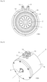
- the electric motor 100 of the invention comprises a rotor 1 whose rotation shaft 3 extends along an extension axis X and a stator 2 arranged around the rotor 1. It also comprises a front bearing 4 comprising a cylindrical portion 5 extending along the extension axis X and a rear bearing 6, having an overall disc shape, assembled together to form an internal cavity 7 making it possible to house the rotor 1 and the stator 2.
- the front bearing 4 is made of aluminum and the rear bearing 6 is made of steel.
- the internal channel 12 has a substantially cylindrical shape whose longitudinal axis extends coaxially to the extension axis X as does the internal chamber 10 which is cylindrical.
- the internal chamber 10 and the internal channel 12 are coaxial, the internal chamber 10 surrounding the internal channel 12 so as to facilitate heat exchange.
- FIG. 5 illustrates another aspect of the invention relating to a motorization system 200 comprising a circulation circuit 20 for heat transfer fluid.
- the circulation circuit 20 successively comprises a heat engine 21, a first pump 22 and an electric motor 100 as previously described. All these elements are fluidically connected in series.
- the first pump 22 makes it possible to drive the circulation of the heat transfer fluid in the circulation circuit 20, from the internal chamber 10 of the electric motor 100 to the heat engine 21 so as to carry out a heat exchange.
- the heat transfer fluid cools the engine electric 100 when it is in operation then transfers the stored calories to the thermal engine 21.
- the motorization system 200 also comprises a refrigerant circuit 23 in which a refrigerant liquid of the electric motor 100 is intended to circulate.
- the refrigerant circuit 23 successively comprises the electric motor 100, a second pump 24 and a heat exchanger 25 fluidly connected in series.
- the refrigerant liquid circulating in the internal channel 12 of the electric motor 100 can be cooled in the heat exchanger 25 thanks to the action of the second pump 24 used to drive the circulation of the refrigerant liquid.
- the heat exchanger 25 is a radiator commonly used in the field.
- the refrigerant liquid is cooled via the air encountered during the circulation of the vehicle.
- the refrigerant circuit 23 and the circulation circuit 20 for heat transfer fluid are configured so that the direction of circulation of the refrigerant liquid is opposite to the direction of circulation of the heat transfer fluid.
- Figure 4 illustrates the heat transfer fluid inlet 9 arranged opposite the refrigerant fluid outlet pipe 14.
- the heat transfer fluid outlet 11 is arranged opposite the refrigerant fluid inlet pipe 13.
- the motorization system 200 comprises a temperature probe configured to measure the temperature of the heat transfer fluid at the inlet of the heat engine 21.
- a controller provided in the first pump 22 makes it possible to communicate with the temperature probe to control the operation or stopping of the first pump 22.
- the controller can in particular control the starting of the first pump 22 to cause the circulation of the heat transfer fluid in the circuit 20 and in the internal chamber 10 when the temperature of the heat transfer fluid measured at the inlet of the heat engine 21 is lower than a predetermined threshold temperature value, chosen so as to optimize the operation of the heat engine 21.
- the controller is configured to command the start of the first pump 22 when the temperature of the heat transfer fluid measured by the probe at the inlet of the heat engine 21 is below the predetermined threshold temperature, for example 90°C.
- the first pump 22 allows the circulation of the heat transfer fluid (here engine lubricating oil) in the internal chamber 10 of the electric motor 100 which heats up with the increase in the internal temperature of the active parts (rotor and stator).
- the controller receives the temperature measurement and the comparison with the predetermined threshold temperature indicates that the temperature of the heat transfer fluid is equal to or greater than approximately 90°C, the controller gives the instruction to stop the first pump 22.
- the heat engine 21 is then in better conditions for its start and then enters its standard operation, commonly used on current heat engines present on the automobile market.
- the electric motor 100 still operates (in the same operating modes as a traction motor) and is cooled by its own glycol circuit 23.
- thermal engine 21 is advantageously intended to limit the CO 2 emission of a cold engine by heating the lubricating oil before its start.
- Other examples of applications can find a benefit in optimal management of the temperature and operation of thermal and electric engines as well as the pollution emitted.
- the present invention makes it possible to improve the cooling of an electric motor 100 in operation by a heat exchange organized in an internal chamber 10 that is easy and inexpensive to manufacture.
- this heat exchange can be used for heat transfer to a device that needs to be heated by creating a fluid circuit for a heat transfer fluid between the outlet of refrigerant fluid and the inlet of the device to be heated.
- the figures illustrate an application to the heating of the lubricating oil of a thermal engine 21 but this system can find other applications, in particular for the heating of the lubricating oil of a gearbox or for the management of the temperature (heating/cooling) of batteries, thermal capacities, etc. without departing from the scope of the invention.
- the invention is obviously not limited to the configuration of the invention as described above.
Landscapes
- Engineering & Computer Science (AREA)
- Power Engineering (AREA)
- Microelectronics & Electronic Packaging (AREA)
- Chemical & Material Sciences (AREA)
- Combustion & Propulsion (AREA)
- Transportation (AREA)
- Mechanical Engineering (AREA)
- Motor Or Generator Cooling System (AREA)
- Connection Of Motors, Electrical Generators, Mechanical Devices, And The Like (AREA)
Claims (9)
- Elektromotor (100), der Folgendes umfasst:- einen Rotor (1), dessen Drehwelle (3) sich entlang einer Erweiterungsachse (X) erstreckt,- einen Stator (2), der um den Rotor (1) herum angeordnet ist,- ein vorderes Lager (4) und ein hinteres Lager (6), die so eingerichtet sind, dass sie zusammengebaut werden und einen inneren Hohlraum (7) bilden, in dem der Rotor (1) und der Stator (2) untergebracht sind, wobei das vordere Lager (4) einen zylindrischen Abschnitt (5) umfasst, der sich entlang der Erweiterungsachse (X) erstreckt, und- einen glockenförmigen Deckel (8), der das hintere Lager (6) und mindestens den zylindrischen Abschnitt (5) des vorderen Lagers (4) vollständig abdeckt, wobei der Deckel (8) so eingerichtet ist, dass er mit dem zylindrischen Abschnitt (5) mindestens einen Innenkanal (12) bildet, der sich mindestens teilweise um den inneren Hohlraum (7) herum erstreckt, wobei der Innenkanal (12) für die Zirkulation einer Kühlflüssigkeit eingerichtet ist, wobei der Deckel (8) eine Innenkammer (10), die sich mindestens teilweise um den inneren Hohlraum (7) herum erstreckt, indem sie den Innenkanal (12) umschließt, einen Wärmeträgermediumeinlass (9) und einen Wärmeträgermediumauslass (11) umfasst, die fluidisch mit der Innenkammer (10) verbunden sind, so dass eine Zirkulation eines Wärmeträgermediums in der Innenkammer (10) ermöglicht wird.
- Elektromotor (100) nach Anspruch 1, wobei der Innenkanal (12) eine im Wesentlichen zylindrische Form aufweist, deren Längsachse sich koaxial zur Erweiterungsachse (X) erstreckt.
- Elektromotor 100 nach einem der Ansprüche 1 bis 2, wobei das Wärmeträgermedium ein Schmieröl wie ein Öl für einen Verbrennungsmotor (21) oder ein Öl für ein Getriebe ist.
- Elektromotor (100) nach einem der vorhergehenden Ansprüche, wobei die Innenkammer (10) zylindrisch ist.
- Elektromotor (100) nach einem der Ansprüche 1 bis 4, wobei die Innenkammer (10) und der Innenkanal (12) koaxial sind.
- Motorisierungssystem (200), das einen Zirkulationskreislauf (20) für ein Wärmeträgermedium umfasst und nacheinander Folgendes enthält:- einen Verbrennungsmotor (21),- eine erste Pumpe (22), und- einen Elektromotor (100) nach einem der Ansprüche 1 bis 5,die fluidisch in Reihe verbunden sind, wobei die erste Pumpe (22) so eingerichtet ist, dass sie die Zirkulation des Wärmeträgermediums im Zirkulationskreislauf (20) von der Innenkammer (10) des Elektromotors (100) zum Verbrennungsmotor (21) antreibt, um einen Wärmetransfer vom Elektromotor (100) zum Verbrennungsmotor (21) zu veranlassen, um mittels des Wärmeträgermediums Wärmeenergie vom Elektromotor (100) zum Verbrennungsmotor (21) zu übertragen.
- Motorisierungssystem (200) nach Anspruch 6, das einen Temperatursensor umfasst, der so eingerichtet ist, dass er die Temperatur des Wärmeträgermediums am Eingang des Verbrennungsmotors (21) misst, und wobei die erste Pumpe (22) eine Steuerung umfasst, die so eingerichtet ist, dass sie mit dem Temperatursensor in Verbindung steht und Folgendes steuert:- das Starten der ersten Pumpe (22), um die Zirkulation des Wärmeträgermediums in der Innenkammer (10) anzutreiben, wenn die vom Temperatursensor gemessene Temperatur des Wärmeträgermediums geringer ist als ein vorbestimmter Schwellenwert, um den Verbrennungsmotor (21) aufzuwärmen, und- das Anhalten der ersten Pumpe (22), um die Zirkulation des Wärmeträgermediums in der Innenkammer (10) anzuhalten, wenn die vom Temperatursensor gemessene Temperatur des Wärmeträgermediums größer ist als ein vorbestimmter Schwellenwert.
- Motorisierungssystem (200) nach einem der Ansprüche 6 oder 7, das einen Kühlkreislauf (23) für die Zirkulation einer Kühlflüssigkeit umfasst und nacheinander Folgendes enthält:
einen Elektromotor (100) nach Anspruch 1 bis 5,- eine zweite Pumpe (24), und- einen Wärmetauscher (25), der so eingerichtet ist, dass er ein Kältemittel kühlt, welche fluidisch in Reihe verbunden sind, wobei die zweite Pumpe (24) so eingerichtet ist, dass sie die Zirkulation der Kühlflüssigkeit im Kühlmittelkreislauf (23) vom Wärmetauscher (25) zum Innenkanal (12) zum Kühlen des Elektromotors (100) antreibt. - Motorisierungssystem (200) nach der Kombination der Ansprüche 6 und 8, wobei der Kühlkreislauf (23) und der Zirkulationskreislauf (20) für ein Wärmeträgermedium so eingerichtet sind, dass die Durchflussrichtung der Kühlflüssigkeit der Durchflussrichtung des Wärmeträgermediums entgegengesetzt ist.
Applications Claiming Priority (2)
| Application Number | Priority Date | Filing Date | Title |
|---|---|---|---|
| FR2007808A FR3112910B1 (fr) | 2020-07-24 | 2020-07-24 | Moteur électrique et système de motorisation pour transfert thermique |
| PCT/FR2021/051389 WO2022018391A1 (fr) | 2020-07-24 | 2021-07-23 | Moteur électrique et système de motorisation pour transfert thermique |
Publications (2)
| Publication Number | Publication Date |
|---|---|
| EP4186149A1 EP4186149A1 (de) | 2023-05-31 |
| EP4186149B1 true EP4186149B1 (de) | 2025-04-16 |
Family
ID=72885775
Family Applications (1)
| Application Number | Title | Priority Date | Filing Date |
|---|---|---|---|
| EP21755805.5A Active EP4186149B1 (de) | 2020-07-24 | 2021-07-23 | Elektromotor und antriebssystem zur wärmeübertragung |
Country Status (5)
| Country | Link |
|---|---|
| US (1) | US12294284B2 (de) |
| EP (1) | EP4186149B1 (de) |
| CN (1) | CN116133885A (de) |
| FR (1) | FR3112910B1 (de) |
| WO (1) | WO2022018391A1 (de) |
Families Citing this family (2)
| Publication number | Priority date | Publication date | Assignee | Title |
|---|---|---|---|---|
| DE102022201139A1 (de) * | 2022-02-03 | 2023-08-03 | Mahle International Gmbh | Baugruppe für eine elektrische Maschine |
| DE102022207938A1 (de) * | 2022-08-01 | 2024-02-01 | Mahle International Gmbh | Wasserpumpe für ein Kühlsystem eines Kraftfahrzeugs |
Family Cites Families (8)
| Publication number | Priority date | Publication date | Assignee | Title |
|---|---|---|---|---|
| FR2756116B1 (fr) * | 1996-11-20 | 1999-01-22 | Valeo Equip Electr Moteur | Alternateur de vehicule automobile comportant un stator enrobe |
| JP4185782B2 (ja) * | 2003-02-13 | 2008-11-26 | トヨタ自動車株式会社 | 車両用駆動装置 |
| US7239032B1 (en) * | 2005-11-18 | 2007-07-03 | Polaris Industries Inc. | Starter-generator |
| JP5075872B2 (ja) * | 2009-05-20 | 2012-11-21 | 本田技研工業株式会社 | 電動機 |
| US9130421B2 (en) * | 2013-03-14 | 2015-09-08 | Remy Technologies, Llc | L-shaped sheet metal cooling jacket with stamped bearing support |
| DE102014223875A1 (de) * | 2014-11-24 | 2016-05-25 | Robert Bosch Gmbh | Gehäuse geeignet für die Aufnahme einer Antriebseinheit eines Elektromotors |
| KR20180070112A (ko) * | 2016-12-16 | 2018-06-26 | 현대자동차주식회사 | 냉각수 열교환 냉각방식 구동모터 및 환경차량 |
| FR3090501B1 (fr) * | 2018-12-21 | 2021-04-09 | Renault Sas | Dispositif de gestion thermique d’un circuit de fluide caloporteur d’un véhicule hybride |
-
2020
- 2020-07-24 FR FR2007808A patent/FR3112910B1/fr active Active
-
2021
- 2021-07-23 WO PCT/FR2021/051389 patent/WO2022018391A1/fr not_active Ceased
- 2021-07-23 EP EP21755805.5A patent/EP4186149B1/de active Active
- 2021-07-23 US US18/017,721 patent/US12294284B2/en active Active
- 2021-07-23 CN CN202180059771.6A patent/CN116133885A/zh active Pending
Also Published As
| Publication number | Publication date |
|---|---|
| FR3112910A1 (fr) | 2022-01-28 |
| US20230268804A1 (en) | 2023-08-24 |
| EP4186149A1 (de) | 2023-05-31 |
| CN116133885A (zh) | 2023-05-16 |
| WO2022018391A1 (fr) | 2022-01-27 |
| US12294284B2 (en) | 2025-05-06 |
| FR3112910B1 (fr) | 2023-04-07 |
Similar Documents
| Publication | Publication Date | Title |
|---|---|---|
| EP3363103B1 (de) | Vorrichtung zur wärmeverwaltung eines elektrischen antriebsstrangs | |
| EP3080523B1 (de) | Elektrische vorrichtung zur thermischen konditionierung der flüssigkeit für ein kraftfahrzeug und entsprechende heiz- und/oder lüftungsvorrichtung | |
| EP4136740B1 (de) | Ölkühlsystem für einen elektromotor | |
| EP0611675B1 (de) | Fahrzeug mit elektrischem Antrieb mit einer Vorrichtung zur Rückgewinnung der Energie | |
| EP3953199A1 (de) | Vorrichtung zur kühlung und schmierung eines elektrischen antriebsstrangs eines elektrischen oder hybriden kraftfahrzeugs | |
| EP4186149B1 (de) | Elektromotor und antriebssystem zur wärmeübertragung | |
| EP2831514B1 (de) | Elektrische heizvorrichtung für ein kraftfahrzeug sowie heizungs-, lüftungs- und/oder klimatisierungsvorrichtung | |
| EP1197644B1 (de) | System und Verfahren zur Kühlung eines Hybridfahrzeugs | |
| WO2008129190A1 (fr) | Dispositif et procede de recuperation d'energie pour moteur a combustion interne de vehicule automobile | |
| EP2758647B1 (de) | Kühlung eines elektromotors über wärmerohre | |
| FR2974954A1 (fr) | Machine electrique et vehicule automobile comprenant une telle machine electrique | |
| EP4360158A1 (de) | Temperiervorrichtung | |
| FR2921125A3 (fr) | Dispositif de prechauffage pour moteur thermique. | |
| FR3077373A1 (fr) | Circuit de gestion thermique d'un vehicule hybride | |
| FR3147849A1 (fr) | Dispositif de régulation thermique pour une boîte de vitesses de véhicule. | |
| EP3000635B1 (de) | Vorrichtung zur fluidwärmekonditionierung für kraftfahrzeug, und entsprechendes heiz- und/oder klimatisierungsgerät | |
| FR3085623A1 (fr) | Procede de gestion d'un dispositif de chauffage a pompe a chaleur de vehicule automobile | |
| FR2910537A1 (fr) | Dispositif et procede de regulation du debit de l'air envoye au travers d'un echangeur de chaleur pour moteur a combustion interne de vehicule automobile | |
| WO2021116579A1 (fr) | Système de propulsion pour véhicule automobile électrique | |
| FR3147850A1 (fr) | Dispositif de régulation thermique pour une boîte de vitesses de véhicule. | |
| EP0841735A1 (de) | Verbesserungen an flüssigkeitsgekühlten Generatoren | |
| FR3116327A1 (fr) | Installation de réchauffage d’un fluide d’un organe de véhicule | |
| WO2023031149A1 (fr) | Dispositif de gestion thermique des batteries pour véhicule électrique ou hybride | |
| FR3059056A1 (fr) | Compresseur electrique de suralimentation pour vehicule automobile | |
| FR2952676A1 (fr) | Circuit de refroidissement d'un moteur a combustion et procede de regulation thermique associe |
Legal Events
| Date | Code | Title | Description |
|---|---|---|---|
| STAA | Information on the status of an ep patent application or granted ep patent |
Free format text: STATUS: UNKNOWN |
|
| STAA | Information on the status of an ep patent application or granted ep patent |
Free format text: STATUS: THE INTERNATIONAL PUBLICATION HAS BEEN MADE |
|
| PUAI | Public reference made under article 153(3) epc to a published international application that has entered the european phase |
Free format text: ORIGINAL CODE: 0009012 |
|
| STAA | Information on the status of an ep patent application or granted ep patent |
Free format text: STATUS: REQUEST FOR EXAMINATION WAS MADE |
|
| 17P | Request for examination filed |
Effective date: 20230109 |
|
| AK | Designated contracting states |
Kind code of ref document: A1 Designated state(s): AL AT BE BG CH CY CZ DE DK EE ES FI FR GB GR HR HU IE IS IT LI LT LU LV MC MK MT NL NO PL PT RO RS SE SI SK SM TR |
|
| DAV | Request for validation of the european patent (deleted) | ||
| DAX | Request for extension of the european patent (deleted) | ||
| RAP3 | Party data changed (applicant data changed or rights of an application transferred) |
Owner name: NOVARES FRANCE |
|
| GRAP | Despatch of communication of intention to grant a patent |
Free format text: ORIGINAL CODE: EPIDOSNIGR1 |
|
| STAA | Information on the status of an ep patent application or granted ep patent |
Free format text: STATUS: GRANT OF PATENT IS INTENDED |
|
| INTG | Intention to grant announced |
Effective date: 20241112 |
|
| GRAS | Grant fee paid |
Free format text: ORIGINAL CODE: EPIDOSNIGR3 |
|
| GRAA | (expected) grant |
Free format text: ORIGINAL CODE: 0009210 |
|
| STAA | Information on the status of an ep patent application or granted ep patent |
Free format text: STATUS: THE PATENT HAS BEEN GRANTED |
|
| AK | Designated contracting states |
Kind code of ref document: B1 Designated state(s): AL AT BE BG CH CY CZ DE DK EE ES FI FR GB GR HR HU IE IS IT LI LT LU LV MC MK MT NL NO PL PT RO RS SE SI SK SM TR |
|
| REG | Reference to a national code |
Ref country code: GB Ref legal event code: FG4D Free format text: NOT ENGLISH |
|
| REG | Reference to a national code |
Ref country code: CH Ref legal event code: EP Ref country code: DE Ref legal event code: R096 Ref document number: 602021029275 Country of ref document: DE |
|
| REG | Reference to a national code |
Ref country code: IE Ref legal event code: FG4D Free format text: LANGUAGE OF EP DOCUMENT: FRENCH |
|
| PGFP | Annual fee paid to national office [announced via postgrant information from national office to epo] |
Ref country code: FR Payment date: 20250630 Year of fee payment: 5 |
|
| REG | Reference to a national code |
Ref country code: NL Ref legal event code: MP Effective date: 20250416 |
|
| PG25 | Lapsed in a contracting state [announced via postgrant information from national office to epo] |
Ref country code: NL Free format text: LAPSE BECAUSE OF FAILURE TO SUBMIT A TRANSLATION OF THE DESCRIPTION OR TO PAY THE FEE WITHIN THE PRESCRIBED TIME-LIMIT Effective date: 20250416 |
|
| REG | Reference to a national code |
Ref country code: AT Ref legal event code: MK05 Ref document number: 1786488 Country of ref document: AT Kind code of ref document: T Effective date: 20250416 |
|
| PG25 | Lapsed in a contracting state [announced via postgrant information from national office to epo] |
Ref country code: FI Free format text: LAPSE BECAUSE OF FAILURE TO SUBMIT A TRANSLATION OF THE DESCRIPTION OR TO PAY THE FEE WITHIN THE PRESCRIBED TIME-LIMIT Effective date: 20250416 Ref country code: PT Free format text: LAPSE BECAUSE OF FAILURE TO SUBMIT A TRANSLATION OF THE DESCRIPTION OR TO PAY THE FEE WITHIN THE PRESCRIBED TIME-LIMIT Effective date: 20250818 Ref country code: ES Free format text: LAPSE BECAUSE OF FAILURE TO SUBMIT A TRANSLATION OF THE DESCRIPTION OR TO PAY THE FEE WITHIN THE PRESCRIBED TIME-LIMIT Effective date: 20250416 |
|
| PGFP | Annual fee paid to national office [announced via postgrant information from national office to epo] |
Ref country code: DE Payment date: 20250630 Year of fee payment: 5 |
|
| REG | Reference to a national code |
Ref country code: LT Ref legal event code: MG9D |
|
| PG25 | Lapsed in a contracting state [announced via postgrant information from national office to epo] |
Ref country code: GR Free format text: LAPSE BECAUSE OF FAILURE TO SUBMIT A TRANSLATION OF THE DESCRIPTION OR TO PAY THE FEE WITHIN THE PRESCRIBED TIME-LIMIT Effective date: 20250717 Ref country code: NO Free format text: LAPSE BECAUSE OF FAILURE TO SUBMIT A TRANSLATION OF THE DESCRIPTION OR TO PAY THE FEE WITHIN THE PRESCRIBED TIME-LIMIT Effective date: 20250716 |
|
| PG25 | Lapsed in a contracting state [announced via postgrant information from national office to epo] |
Ref country code: PL Free format text: LAPSE BECAUSE OF FAILURE TO SUBMIT A TRANSLATION OF THE DESCRIPTION OR TO PAY THE FEE WITHIN THE PRESCRIBED TIME-LIMIT Effective date: 20250416 |
|
| PG25 | Lapsed in a contracting state [announced via postgrant information from national office to epo] |
Ref country code: BG Free format text: LAPSE BECAUSE OF FAILURE TO SUBMIT A TRANSLATION OF THE DESCRIPTION OR TO PAY THE FEE WITHIN THE PRESCRIBED TIME-LIMIT Effective date: 20250416 |
|
| PG25 | Lapsed in a contracting state [announced via postgrant information from national office to epo] |
Ref country code: HR Free format text: LAPSE BECAUSE OF FAILURE TO SUBMIT A TRANSLATION OF THE DESCRIPTION OR TO PAY THE FEE WITHIN THE PRESCRIBED TIME-LIMIT Effective date: 20250416 |
|
| PG25 | Lapsed in a contracting state [announced via postgrant information from national office to epo] |
Ref country code: AT Free format text: LAPSE BECAUSE OF FAILURE TO SUBMIT A TRANSLATION OF THE DESCRIPTION OR TO PAY THE FEE WITHIN THE PRESCRIBED TIME-LIMIT Effective date: 20250416 |
|
| PG25 | Lapsed in a contracting state [announced via postgrant information from national office to epo] |
Ref country code: RS Free format text: LAPSE BECAUSE OF FAILURE TO SUBMIT A TRANSLATION OF THE DESCRIPTION OR TO PAY THE FEE WITHIN THE PRESCRIBED TIME-LIMIT Effective date: 20250716 |
|
| PG25 | Lapsed in a contracting state [announced via postgrant information from national office to epo] |
Ref country code: IS Free format text: LAPSE BECAUSE OF FAILURE TO SUBMIT A TRANSLATION OF THE DESCRIPTION OR TO PAY THE FEE WITHIN THE PRESCRIBED TIME-LIMIT Effective date: 20250816 |
|
| PG25 | Lapsed in a contracting state [announced via postgrant information from national office to epo] |
Ref country code: LV Free format text: LAPSE BECAUSE OF FAILURE TO SUBMIT A TRANSLATION OF THE DESCRIPTION OR TO PAY THE FEE WITHIN THE PRESCRIBED TIME-LIMIT Effective date: 20250416 |
|
| PG25 | Lapsed in a contracting state [announced via postgrant information from national office to epo] |
Ref country code: DK Free format text: LAPSE BECAUSE OF FAILURE TO SUBMIT A TRANSLATION OF THE DESCRIPTION OR TO PAY THE FEE WITHIN THE PRESCRIBED TIME-LIMIT Effective date: 20250416 Ref country code: SM Free format text: LAPSE BECAUSE OF FAILURE TO SUBMIT A TRANSLATION OF THE DESCRIPTION OR TO PAY THE FEE WITHIN THE PRESCRIBED TIME-LIMIT Effective date: 20250416 |
|
| REG | Reference to a national code |
Ref country code: DE Ref legal event code: R097 Ref document number: 602021029275 Country of ref document: DE |
|
| PG25 | Lapsed in a contracting state [announced via postgrant information from national office to epo] |
Ref country code: CZ Free format text: LAPSE BECAUSE OF FAILURE TO SUBMIT A TRANSLATION OF THE DESCRIPTION OR TO PAY THE FEE WITHIN THE PRESCRIBED TIME-LIMIT Effective date: 20250416 |
|
| PG25 | Lapsed in a contracting state [announced via postgrant information from national office to epo] |
Ref country code: EE Free format text: LAPSE BECAUSE OF FAILURE TO SUBMIT A TRANSLATION OF THE DESCRIPTION OR TO PAY THE FEE WITHIN THE PRESCRIBED TIME-LIMIT Effective date: 20250416 |
|
| PG25 | Lapsed in a contracting state [announced via postgrant information from national office to epo] |
Ref country code: SK Free format text: LAPSE BECAUSE OF FAILURE TO SUBMIT A TRANSLATION OF THE DESCRIPTION OR TO PAY THE FEE WITHIN THE PRESCRIBED TIME-LIMIT Effective date: 20250416 |
|
| PG25 | Lapsed in a contracting state [announced via postgrant information from national office to epo] |
Ref country code: IT Free format text: LAPSE BECAUSE OF FAILURE TO SUBMIT A TRANSLATION OF THE DESCRIPTION OR TO PAY THE FEE WITHIN THE PRESCRIBED TIME-LIMIT Effective date: 20250416 |
|
| PLBE | No opposition filed within time limit |
Free format text: ORIGINAL CODE: 0009261 |
|
| STAA | Information on the status of an ep patent application or granted ep patent |
Free format text: STATUS: NO OPPOSITION FILED WITHIN TIME LIMIT |
|
| REG | Reference to a national code |
Ref country code: CH Ref legal event code: H13 Free format text: ST27 STATUS EVENT CODE: U-0-0-H10-H13 (AS PROVIDED BY THE NATIONAL OFFICE) Effective date: 20260224 |
|
| REG | Reference to a national code |
Ref country code: CH Ref legal event code: L10 Free format text: ST27 STATUS EVENT CODE: U-0-0-L10-L00 (AS PROVIDED BY THE NATIONAL OFFICE) Effective date: 20260225 |
|
| PG25 | Lapsed in a contracting state [announced via postgrant information from national office to epo] |
Ref country code: RO Free format text: LAPSE BECAUSE OF FAILURE TO SUBMIT A TRANSLATION OF THE DESCRIPTION OR TO PAY THE FEE WITHIN THE PRESCRIBED TIME-LIMIT Effective date: 20250416 |
|
| PG25 | Lapsed in a contracting state [announced via postgrant information from national office to epo] |
Ref country code: LU Free format text: LAPSE BECAUSE OF NON-PAYMENT OF DUE FEES Effective date: 20250723 |
|
| 26N | No opposition filed |
Effective date: 20260119 |
|
| GBPC | Gb: european patent ceased through non-payment of renewal fee |
Effective date: 20250723 |
|
| REG | Reference to a national code |
Ref country code: BE Ref legal event code: MM Effective date: 20250731 |
|
| PG25 | Lapsed in a contracting state [announced via postgrant information from national office to epo] |
Ref country code: GB Free format text: LAPSE BECAUSE OF NON-PAYMENT OF DUE FEES Effective date: 20250723 |
|
| PG25 | Lapsed in a contracting state [announced via postgrant information from national office to epo] |
Ref country code: BE Free format text: LAPSE BECAUSE OF NON-PAYMENT OF DUE FEES Effective date: 20250731 |