EP4186157B1 - Parameteridentifikationsverfahren für drehfeldmaschinen und regelvorrichtung damit - Google Patents
Parameteridentifikationsverfahren für drehfeldmaschinen und regelvorrichtung damit Download PDFInfo
- Publication number
- EP4186157B1 EP4186157B1 EP21769393.6A EP21769393A EP4186157B1 EP 4186157 B1 EP4186157 B1 EP 4186157B1 EP 21769393 A EP21769393 A EP 21769393A EP 4186157 B1 EP4186157 B1 EP 4186157B1
- Authority
- EP
- European Patent Office
- Prior art keywords
- current
- control
- stator
- electric machine
- determined
- Prior art date
- Legal status (The legal status is an assumption and is not a legal conclusion. Google has not performed a legal analysis and makes no representation as to the accuracy of the status listed.)
- Active
Links
Images


Classifications
-
- H—ELECTRICITY
- H02—GENERATION; CONVERSION OR DISTRIBUTION OF ELECTRIC POWER
- H02P—CONTROL OR REGULATION OF ELECTRIC MOTORS, ELECTRIC GENERATORS OR DYNAMO-ELECTRIC CONVERTERS; CONTROLLING TRANSFORMERS, REACTORS OR CHOKE COILS
- H02P21/00—Arrangements or methods for the control of electric machines by vector control, e.g. by control of field orientation
- H02P21/14—Estimation or adaptation of machine parameters, e.g. flux, current or voltage
- H02P21/16—Estimation of constants, e.g. the rotor time constant
-
- H—ELECTRICITY
- H02—GENERATION; CONVERSION OR DISTRIBUTION OF ELECTRIC POWER
- H02P—CONTROL OR REGULATION OF ELECTRIC MOTORS, ELECTRIC GENERATORS OR DYNAMO-ELECTRIC CONVERTERS; CONTROLLING TRANSFORMERS, REACTORS OR CHOKE COILS
- H02P21/00—Arrangements or methods for the control of electric machines by vector control, e.g. by control of field orientation
- H02P21/0003—Control strategies in general, e.g. linear type, e.g. P, PI, PID, using robust control
- H02P21/0025—Control strategies in general, e.g. linear type, e.g. P, PI, PID, using robust control implementing a off line learning phase to determine and store useful data for on-line control
-
- H—ELECTRICITY
- H02—GENERATION; CONVERSION OR DISTRIBUTION OF ELECTRIC POWER
- H02P—CONTROL OR REGULATION OF ELECTRIC MOTORS, ELECTRIC GENERATORS OR DYNAMO-ELECTRIC CONVERTERS; CONTROLLING TRANSFORMERS, REACTORS OR CHOKE COILS
- H02P21/00—Arrangements or methods for the control of electric machines by vector control, e.g. by control of field orientation
- H02P21/14—Estimation or adaptation of machine parameters, e.g. flux, current or voltage
-
- H—ELECTRICITY
- H02—GENERATION; CONVERSION OR DISTRIBUTION OF ELECTRIC POWER
- H02P—CONTROL OR REGULATION OF ELECTRIC MOTORS, ELECTRIC GENERATORS OR DYNAMO-ELECTRIC CONVERTERS; CONTROLLING TRANSFORMERS, REACTORS OR CHOKE COILS
- H02P21/00—Arrangements or methods for the control of electric machines by vector control, e.g. by control of field orientation
- H02P21/22—Current control, e.g. using a current control loop
-
- H—ELECTRICITY
- H02—GENERATION; CONVERSION OR DISTRIBUTION OF ELECTRIC POWER
- H02P—CONTROL OR REGULATION OF ELECTRIC MOTORS, ELECTRIC GENERATORS OR DYNAMO-ELECTRIC CONVERTERS; CONTROLLING TRANSFORMERS, REACTORS OR CHOKE COILS
- H02P21/00—Arrangements or methods for the control of electric machines by vector control, e.g. by control of field orientation
- H02P21/24—Vector control not involving the use of rotor position or rotor speed sensors
- H02P21/32—Determining the initial rotor position
-
- H—ELECTRICITY
- H02—GENERATION; CONVERSION OR DISTRIBUTION OF ELECTRIC POWER
- H02P—CONTROL OR REGULATION OF ELECTRIC MOTORS, ELECTRIC GENERATORS OR DYNAMO-ELECTRIC CONVERTERS; CONTROLLING TRANSFORMERS, REACTORS OR CHOKE COILS
- H02P21/00—Arrangements or methods for the control of electric machines by vector control, e.g. by control of field orientation
- H02P21/34—Arrangements for starting
-
- H—ELECTRICITY
- H02—GENERATION; CONVERSION OR DISTRIBUTION OF ELECTRIC POWER
- H02P—CONTROL OR REGULATION OF ELECTRIC MOTORS, ELECTRIC GENERATORS OR DYNAMO-ELECTRIC CONVERTERS; CONTROLLING TRANSFORMERS, REACTORS OR CHOKE COILS
- H02P9/00—Arrangements for controlling electric generators for the purpose of obtaining a desired output
- H02P9/14—Arrangements for controlling electric generators for the purpose of obtaining a desired output by variation of field
-
- G—PHYSICS
- G01—MEASURING; TESTING
- G01R—MEASURING ELECTRIC VARIABLES; MEASURING MAGNETIC VARIABLES
- G01R27/00—Arrangements for measuring resistance, reactance, impedance, or electric characteristics derived therefrom
- G01R27/02—Measuring real or complex resistance, reactance, impedance, or other two-pole characteristics derived therefrom, e.g. time constant
- G01R27/08—Measuring resistance by measuring both voltage and current
-
- H—ELECTRICITY
- H02—GENERATION; CONVERSION OR DISTRIBUTION OF ELECTRIC POWER
- H02P—CONTROL OR REGULATION OF ELECTRIC MOTORS, ELECTRIC GENERATORS OR DYNAMO-ELECTRIC CONVERTERS; CONTROLLING TRANSFORMERS, REACTORS OR CHOKE COILS
- H02P2203/00—Indexing scheme relating to controlling arrangements characterised by the means for detecting the position of the rotor
- H02P2203/03—Determination of the rotor position, e.g. initial rotor position, during standstill or low speed operation
-
- H—ELECTRICITY
- H02—GENERATION; CONVERSION OR DISTRIBUTION OF ELECTRIC POWER
- H02P—CONTROL OR REGULATION OF ELECTRIC MOTORS, ELECTRIC GENERATORS OR DYNAMO-ELECTRIC CONVERTERS; CONTROLLING TRANSFORMERS, REACTORS OR CHOKE COILS
- H02P2203/00—Indexing scheme relating to controlling arrangements characterised by the means for detecting the position of the rotor
- H02P2203/11—Determination or estimation of the rotor position or other motor parameters based on the analysis of high-frequency signals
-
- H—ELECTRICITY
- H02—GENERATION; CONVERSION OR DISTRIBUTION OF ELECTRIC POWER
- H02P—CONTROL OR REGULATION OF ELECTRIC MOTORS, ELECTRIC GENERATORS OR DYNAMO-ELECTRIC CONVERTERS; CONTROLLING TRANSFORMERS, REACTORS OR CHOKE COILS
- H02P2207/00—Indexing scheme relating to controlling arrangements characterised by the type of motor
- H02P2207/01—Asynchronous machines
-
- H—ELECTRICITY
- H02—GENERATION; CONVERSION OR DISTRIBUTION OF ELECTRIC POWER
- H02P—CONTROL OR REGULATION OF ELECTRIC MOTORS, ELECTRIC GENERATORS OR DYNAMO-ELECTRIC CONVERTERS; CONTROLLING TRANSFORMERS, REACTORS OR CHOKE COILS
- H02P2207/00—Indexing scheme relating to controlling arrangements characterised by the type of motor
- H02P2207/05—Synchronous machines, e.g. with permanent magnets or DC excitation
Definitions
- the invention relates to a method for determining control parameters for controlling an electric drive by means of vector control, wherein the electric drive has at least one electric machine.
- the invention further relates to a control device for an electric drive by means of vector control and an electric drive with such a control device, a frequency converter and an electric machine.
- An electric drive often has at least one frequency converter and one electric machine.
- the frequency converter controls or regulates the electric machine.
- One approach is vector control.
- To parameterize the vector control of the frequency converter parameters of the electric machine are required, which often result from the physical description, simulation or modeling of the electric machine. The required data is often not available at all, is incomplete or is incorrect as equivalent circuit diagram data.
- the parameters required for control are also referred to as control parameters.
- control parameters are also referred to as control parameters.
- the parameters of the electric machine also known as motor parameters, are determined during commissioning using different approaches and tests, which is sometimes very time-consuming.
- the EP 2 421 146 A1 discloses a method for the encoder-free identification of magnetomechanical parameters, in particular mass moment of inertia J and permanent magnet flux between rotor and stator of a three-phase synchronous motor.
- the document BENN LC ET AL "PWM spectrum analysis and optimization for model based condition monitoring and control", CONFERENCE RECORD OF THE 2001 IEEE INDUSTRY APPLICATIONS CONFERENCE. 36TH IAS ANNUAL MEETING . CHICAGO, IL, SEPTEMBER 30 - OCT. 4, 2001 ; [ CONFERENCE RECORD OF THE IEEE INDUSTRY APPLICATIONS CONFERENCE. IAS ANNUAL MEETING], NEW YORK, NY : IEEE, US, 30 September 2001 (2001-09-30), page 1311, DOI: 10.1109/IAS.2001.955686, ISBN: 978-0-7803-7114-9 discloses a PWM spectrum analysis and optimization for model-based condition monitoring and control using PRBS with shift registers.
- the invention is based on the object of improving the commissioning of the electric drive.
- a method for determining control parameters for controlling an electric drive by means of a vector control wherein the electric drive has at least one electric machine, wherein a current vector is applied as a signal to three-phase winding connections of the electrical machine, wherein a d-component and a q-component of a stator voltage and a stator current are measured at the winding connections, wherein in a first measuring step a rotating current vector is applied to the three-phase winding connections and the electrical machine is aligned such that an excitation current in the q-axis assumes a minimum, wherein in a second measuring step with the rotor of the electrical machine stationary a field winding of the electrical machine is short-circuited and a current vector in the form of a binary noise signal is applied to the three-phase winding connections, wherein a stator impedance is determined as a first control parameter from the measured d-component and the q-component of the stator voltage and the stator current.
- this object is achieved by a control device for an electric drive for carrying out vector control, wherein the control device is set up to carry out such a method, wherein at least one control parameter for the vector control can be determined and stored by means of the control device in a commissioning phase, wherein after completion of the commissioning phase at least one stored control parameter can be used for the vector control.
- a control device for an electric drive for carrying out vector control wherein the control device is set up to carry out such a method, wherein at least one control parameter for the vector control can be determined and stored by means of the control device in a commissioning phase, wherein after completion of the commissioning phase at least one stored control parameter can be used for the vector control.
- an electric drive having a frequency converter and at least one electric machine, wherein the frequency converter has such a control device, wherein a voltage measuring device and a current measuring device are arranged in the electrical connection between the frequency converter and the electric machine.
- the invention is based, among other things, on the finding that commissioning can be improved by measuring the impedances in the d-axis and the q-axis during standstill, for example by means of the control device. of the electrical machine.
- the electrical machine is also referred to as a motor.
- the rotor of the electrical machine is first aligned and then held in place.
- stator currents and stator voltages are then measured at the connection terminals of the motor.
- the required equivalent circuit data is then determined using a numerical method such as Gauss or Newton. Since these corresponding values are required as parameters for the control, in particular for vector control, these values are also referred to as control parameters.
- the measurement can be carried out by a measuring device, also referred to as a measuring box.
- This measuring box can be operated with a comparatively low operating voltage of, for example, 24V or 48V.
- the measuring device can be part of the control device or can be arranged outside the control device. In any case, it is a measuring device for an electric drive for determining control parameters of a vector control, wherein the measuring device is set up to carry out the method according to one of claims 1 to 5.
- the electrical machine is measured in the d- and q-axes.
- the d-component and the q-component of stator current and/or stator voltage are measured.
- a current indicator in the form of a binary noise signal.
- the current vector is positioned by setting the commutation angle accordingly.
- the d-component and q-component of the stator current and/or the stator voltage are measured.
- the current in the short-circuited field winding can also be measured.
- an individual control parameter or frequency response of the stator impedance can be calculated as a control parameter.
- the frequency response of the ratio of field to stator current can be calculated as a further control parameter.
- the binary noise signal is generated by a pseudorandom number sequence with a feedback shift register, wherein the shift register has a shift clock, wherein a predeterminable frequency spectrum is generated by means of the shift clock.
- a feedback Shift register By generating the noise signal by means of a feedback Shift registers make it particularly easy to assign the frequency spectrum.
- This current indicator can be easily generated, for example, in a power converter that supplies the electrical machine, and the measurement signals can also be easily assigned to a corresponding frequency in an evaluation of the frequency response.
- the shift clock with which the bits are shifted through the register can be set in an advantageous manner. Different shift clocks can be used to generate corresponding spectra.
- the number of periods is defined for each shift clock in order to determine the accuracy of the measurement and the duration of the measurement.
- both the measurement and the evaluation can be easily carried out in a control unit of the power converter that supplies the electrical machine. This also makes it possible to carry out this parameter identification automatically.
- the stator impedance is determined as a function of the frequency using a fast Fourier transformation.
- the fast Fourier transformation is a simple numerical evaluation of the measurement data and allows not only a single frequency-independent parameter to be generated, but also a frequency response as a control parameter. This allows the operating points and the behavior of the electrical machine to be described much more precisely. This makes it much easier and more precise to control the electrical machine. In addition, critical operating points, for example due to resonances, can also be described more precisely. The control system is then able to generate stable control behavior at these operating points as well.
- the frequency response of the stator impedance is calculated for the real part and the imaginary part of the stator impedance. It has proven advantageous to calculate the complex value of the impedance as Real and imaginary parts must be specified. This results in a physical reference to the values of the equivalent circuit. Since this often forms the basis and the physical reference to the controlled variables, the control system can be set up particularly simply. Errors in parameter identification can also be easily determined based on plausibility checks. This division therefore results in a particularly robust and less error-prone control system.
- the field current is measured through the short-circuited field winding, whereby the ratio of field current to stator current is determined as a second control parameter from the field current and the d-component of the stator current. In this way, further control parameters can be determined which allow the control behavior to be further improved.
- the determined, calculated and/or specified control parameters are stored for use in the vector control.
- the parameters can also be determined outside the control device. But even if they are determined in the control device, this determination can be carried out using separate software routines. After this determination has been completed, the data is stored and used to control the drive, in particular for the vector control.
- the different software routines such as determining the control parameters and implementing the control using vector control can then be carried out independently of one another. This allows the structure of the control device to be optimized.
- the FIG 1 shows an electric drive 1 with an electric machine 2 that is supplied with electrical energy via a frequency converter 5.
- the frequency converter 5 has a control device 4.
- This control device 4 has a measuring device 3 for carrying out the proposed method.
- This measuring device 3 does not necessarily have to be part of the frequency converter 5 or part of the control device 4. However, it is advisable to use the frequency converter 5 as a voltage source for the electric drive 1, the voltage of which is specified by the measuring device 3.
- Winding connections U, V, W are the connection terminals of the electric machine 2. These are connected to the stator winding of the electric machine 2.
- the stator current is measured at the winding connections U, V, W using current measuring devices 6 and the voltage between the winding connections is measured using a voltage measuring device 8. It is sufficient to determine only two of the three voltages or currents, since the third voltage or current can be mathematically determined from the other two.
- the signals from the current measuring devices 6 and the voltage measuring device 8 are transmitted to the measuring device 3.
- the electric machine 2 has a field winding 7 in the rotor, also referred to as the rotor winding.
- the field winding 7 is short-circuited by means of a further current measuring device 9.
- the current measured in this process can also be transmitted to the measuring device 3.
- the excitation current can be determined from the signal of the further current measuring device 9, with which the alignment of the d and q axes can be carried out.
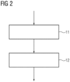
- the FIG 2 shows a flow chart of the parameter determination.
- the electrical machine is aligned. This means that the position of the d-axis and the q-axis, which is offset by 90°, is determined.
- a rotating current indicator is fed into the electrical machine 2, whereby the q-axis is detected when the excitation current is at a minimum.
- the process switches to the second measurement step 12.
- the stator currents and the stator voltages are measured and the stator impedance Zd is determined as the first control parameter.
- These measurements can be carried out over a frequency range, so that the stator impedance is obtained as a frequency response, i.e. as a function of different values of the frequency.
- control device can use this data to carry out the vector control and to precisely and stably control the electrical machine 2.
- FIG 3 shows a typical measurement result of the stator impedance, divided into real and imaginary parts.
- the left ordinate indicates the numerical values for the real part, the right ordinate for the imaginary part. From these measurement points, the frequency response of the stator impedance can be determined using known interpolation methods.
- the invention relates to a method for determining parameters for controlling an electric drive, wherein the electric drive has at least one electric machine.
- a current indicator is applied as a signal to three-phase winding connections of the electric machine, wherein a d-component and a q-component of the stator voltage and the stator current are measured at the winding connections, wherein in a first measuring step a rotating current indicator is applied to the three-phase winding connections are applied and the electrical machine is aligned in such a way that an excitation current in the q-axis assumes a minimum, wherein in a second measuring step, with the rotor of the electrical machine stationary, a field winding of the electrical machine is short-circuited and a current indicator in the form of a binary noise signal is applied to the winding connections, wherein a stator impedance is determined from the measured values as a first control parameter.
- the invention further relates to a control device for an electrical drive, wherein a d-component and a
Landscapes
- Engineering & Computer Science (AREA)
- Power Engineering (AREA)
- Databases & Information Systems (AREA)
- Control Of Ac Motors In General (AREA)
Description
- Die Erfindung betrifft ein Verfahren zur Bestimmung von Regelparametern zur Regelung eines elektrischen Antriebs mittels einer Vektorregelung, wobei der elektrische Antrieb mindestens eine elektrische Maschine aufweist. Ferner betrifft die Erfindung eine Regelvorrichtung für einen elektrischen Antrieb mittels Vektorregelung sowie einen elektrischen Antrieb mit einer derartigen Regelvorrichtung, einem Frequenzumrichter und einer elektrischen Maschine.
- Ein elektrischer Antrieb weist oftmals zumindest einen Frequenzumrichter und eine elektrische Maschine auf. Dabei steuert oder regelt der Frequenzumrichter die elektrische Maschine. Für die Regelung gibt es verschiedene mathematische Ansätze. Ein Ansatz ist die Vektorregelung. Zur Parametrierung der Vektorregelung des Frequenzumrichters werden dabei Parameter der elektrischen Maschine benötigt, die sich oftmals aus der physikalischen Beschreibung, Nachbildung oder Modellierung der elektrischen Maschine ergeben. Die benötigten Daten liegen dabei als Ersatzschaltbilddaten häufig gar nicht, unvollständig oder fehlerhaft vor. Die für die Regelung benötigten Parameter werden auch als Regelparameter bezeichnet. Derzeit werden die Parameter der elektrischen Maschine, auch als Motorparameter bezeichnet, während der Inbetriebsetzung teilweise sehr zeitaufwendig durch unterschiedliche Herangehensweise und Versuche ermittelt.
- Das Dokument HASNI M. ET AL: "Synchronous machine parameter identification in frequency and time domain", SERBIAN JOURNALOF ELECTRICAL ENGINEERING, Bd. 4, Nr. 11. Januar 2007 (2007-01-01), Seiten 51-69, ISSN: 1451-4869, DOI: 10.2298/SJEE0701051H offenbart Synchronmaschineparameteridentifikation im Frequenz- und Zeitbereich.
- Die
EP 2 421 146 A1 offenbart ein Verfahren zur drehgeberlosen Identifikation magnetomechanischer Kenngrößen, insbesondere Massenträgheitsmoment J und Permanentmagnetfluss zwischen Rotor und Stator eines Drehstrom-Synchronmotors. - Das Dokument BENN L C ET AL: "PWM spectrum analysis and optimization for model based condition monitoring and control", CONFERENCE RECORD OF THE 2001 IEEE INDUSTRY APPLICATIONS CONFERENCE. 36TH IAS ANNUAL MEETING . CHICAGO, IL, SEPT. 30 - OCT. 4, 2001; [CONFERENCE RECORD OF THE IEEE INDUSTRY APPLICATIONS CONFERENCE. IAS ANNUAL MEETING], NEW YORK, NY : IEEE, US, 30. September 2001 (2001-09-30), Seite 1311, DOI: 10.1109/IAS.2001.955686, ISBN: 978-0-7803-7114-9 offenbart eine PWM-Spektrumanalyse und - Optimierung für modellbasierte Zustandsüberwachung und -steuerung unter Verwendung von PRBS mit Schieberegistern.
- Der Erfindung liegt die Aufgabe zugrunde, die Inbetriebsetzung des elektrischen Antriebs zu verbessern.
- Diese Aufgabe wird durch ein Verfahren zur Bestimmung von Regelparametern zur Regelung eines elektrischen Antriebs mittels einer Vektorregelung gelöst, wobei der elektrische Antrieb mindestens eine elektrische Maschine aufweist, wobei an dreiphasigen Wicklungsanschlüssen der elektrischen Maschine als Signal ein Stromzeiger angelegt wird, wobei jeweils eine d-Komponente und eine q-Komponente einer Statorspannung und eines Statorstroms an den Wicklungsanschlüssen gemessen wird, wobei in einem ersten Messschritt ein rotierender Stromzeiger an die dreiphasigen Wicklungsanschlüssen angelegt wird und die elektrische Maschine derart ausgerichtet wird, dass ein Erregerstrom in der q-Achse ein Minimum annimmt, wobei in einem zweiten Messschritt bei feststehendem Rotor der elektrischen Maschine eine Feldwicklung der elektrischen Maschine kurzgeschlossen und an die dreiphasigen Wicklungsanschlüsse ein Stromzeiger in Form eines binären Rauschsignals angelegt wird, wobei aus der gemessenen d-Komponente und der q-Komponente der Statorspannung und des Statorstroms eine Statorimpedanz als ein erster Regelparameter bestimmt wird. Ferner wird diese Aufgabe durch eine Regelvorrichtung für einen elektrischen Antrieb zur Durchführung einer Vektorregelung gelöst, wobei die Regelvorrichtung zur Durchführung eines derartigen Verfahrens eingerichtet ist, wobei mittels der Regelvorrichtung in einer Inbetriebsetzungsphase mindestens ein Regelparameter für die Vektorregelung bestimmbar und speicherbar ist, wobei nach Abschluss der Inbetriebsetzungsphase mindestens ein gespeicherter Regelparameter für die Vektorregelung verwendbar ist. Diese Aufgabe wird weiter durch einen elektrischen Antrieb, aufweisend einen Frequenzumrichter und mindestens eine elektrische Maschine gelöst, wobei der Frequenzumrichter eine derartige Regelvorrichtung aufweist, wobei eine Spannungsmessvorrichtung und eine Strommessvorrichtung in der elektrischen Verbindung zwischen Frequenzumrichter und elektrischer Maschine angeordnet sind.
- Weitere vorteilhafte Ausgestaltungen der Erfindung sind in den abhängigen Ansprüchen angegeben.
- Der Erfindung liegt unter anderem die Erkenntnis zugrunde, dass sich die Inbetriebnahme dadurch verbessern lässt, dass sich in einer Stillstandsmessung beispielsweise mittels der Regelvorrichtung, die Impedanzen in der d-Achse und der q-Achse der elektrischen Maschine ermitteln lassen. Im Folgenden wird die elektrische Maschine auch als Motor bezeichnet. Dazu wird der Rotor der elektrischen Maschine zuerst ausgerichtet und dann festgehalten. Durch die Beaufschlagung der elektrischen Motoranschlüsse mit einem binären Rauschsignal werden dann Statorströme und Statorspannungen an den Anschlussklemmen des Motors gemessen. Mit einem numerischen Verfahren, wie beispielsweise nach Gauß oder Newton werden dann die benötigten Ersatzschaltbilddaten ermittelt. Da diese entsprechenden Werte als Parameter für die Regelung, insbesondere für die Vektorregelung, benötigt werden, werden diese Werte auch als Regelparameter bezeichnet. Diese können unabhängig von der Frequenz der Regelung zur Verfügung gestellt werden oder auch in Abhängigkeit von der Frequenz als sogenannter Frequenzgang ermittelt werden. Durch die Verwendung des Frequenzgangs als Regelparameter kann das Verhalten der Regelung in einzelnen Arbeitspunkten optimiert werden. Gerade beim Vorhandensein von Resonanzstellen kann die Regelung stabilisiert werden und Rückwirkungen auf die Last oder das Energieversorgungsnetz reduziert werden.
- Die Messung kann dabei von einer Messvorrichtung, auch als Messbox bezeichnet, durchgeführt werden. Diese Messbox kann mit vergleichsweise niedriger Betriebsspannung von beispielsweise 24V oder 48V betrieben werden. Diese überträgt die ermittelten, berechneten und/oder bestimmten Daten an die Vektorregelung. Dabei kann die Messvorrichtung Teil der Regelvorrichtung sein oder auch außerhalb der Regelvorrichtung angeordnet sein. Auf jeden Fall handelt es sich um eine Messvorrichtung für einen elektrischen Antrieb zur Bestimmung von Regelparametern einer Vektorregelung, wobei die Messvorrichtung zur Durchführung des Verfahrens nach einem der Ansprüche 1 bis 5 eingerichtet ist.
- Die elektrische Maschine wird dabei in d- und q-Achse vermessen. Dazu werden die d-Komponente und die q-Komponente von Statorstrom und/oder Statorspannung gemessen. Zur Anregung der Messung wird ein Stromzeiger in Form eines binären Rauschsignals verwendet. Die Positionierung des Stromzeigers erfolgt mittels entspr. Einstellung des Kommutierungswinkels. Es wird jeweils d-Komponente und q-Komponente des Statorstroms und/oder der Statorspannung gemessen. Um weitere Regelparameter zu erhalten kann auch der Strom in der kurzgeschlossenen Feldwicklung gemessen werden. Nach entsprechender Aufbereitung beispielsweise durch eine Fast Fourier Transformation (FFT) der Daten kann ein einzelner Regelparameter oder Frequenzgänge der Statorimpedanz als Regelparameter berechnet werden. Darüber hinaus kann bei Messung in der d-Achse der Frequenzgang des Verhältnisses von Feld- zu Statorstrom als weiterer Regelparameter berechnet werden.
- Dann können diese Frequenzgänge auf Basis der bekannten Ersatzschaltbildern in d- und q-Achse ermittelt und mittels geschickter Wahl von Ersatzschaltbildelementen in Widerstände, Induktivitäten und des Windungszahlenverhältnisses zwischen Feld- und Statorwicklung derart überführt werden, dass sich eine möglichst gute Übereinstimmung herstellen lässt. Dazu können bekannte Interpolationsverfahren verwendet werden. Damit die Messung an definierten Positionen stattfindet, wird in dem ersten Messschritt über ein Minimum im Erregerstrom, die q-Achse detektiert. Der Stromzeiger wird mit einer sehr geringen Frequenz in der Maschine rotiert. Gleichzeitig ist über eine weitere Strommessvorrichtung die Feldwicklung kurzgeschlossen, so dass auch der Feldstrom gemessen werden kann. Das induzierte Signal auf der Feldwicklung erreicht in der q-Achse ein Minimum. Der dazugehörige Transformationswinkel entspricht dann der q-Achse. Der Erregerstrom kann dabei über den Feldstrom oder über den Statorstrom ermittelt werden.
- Erfindungsgemäß wird das binäres Rauschsignal durch eine Pseudozufallszahlenfolge mit einem rückgekoppeltem Schieberegister erzeugt, wobei das Schieberegister einen Schiebetakt aufweist, wobei mittels des Schiebetaktes ein vorgebbares Frequenzspektrum erzeugt wird. Durch die Erzeugung des Rauschsignals mittels einem rückgekoppelten Schieberegisters ist auf besonders einfache Weise eine einfache Zuordnung zum Frequenzspektrum möglich. Dieser Stromzeiger ist sowohl auf einfache Weise beispielsweise in einem Stromrichter, der die elektrische Maschine speist, erzeugbar und darüber hinaus sind die Messignale auf einfache Weise in einer Auswertung des Frequenzganges einer entsprechenden Frequenz zuordbar. Der Schiebetakt, mit welchem die Bits durch das Register geschoben werden, ist dabei in vorteilhafter Weise einstellbar. Mit verschiedenen Schiebetakten können dabei entsprechende Spektren erzeugt werden. Zusätzlich wird zu jedem Schiebetakt die Anzahl der Perioden definiert, um die Genauigkeit der Messung und die Dauer der Messung festzulegen. Mit dem Rauschsignal auf Basis der Pseudozufallszahlenfolge kann sowohl die Messung als auch die Auswertung auf einfache Weise in einer Regel- oder Steuereinheit des Stromrichters erfolgen, der die elektrische Maschine speist. Dadurch ist es auch möglich, diese Parameteridentifikation automatisiert auszuführen.
- Bei einer weiteren vorteilhaften Ausgestaltung der Erfindung wird die Statorimpedanz in Abhängigkeit von der Frequenz mittels einer Fast Fouriertransformation ermittelt wird. Die Fast Fourier Transformation ist eine einfache numerische Auswertung der Messdaten und erlaubt, nicht nur einen einzelnen frequenzunabhängigen Parameter zu generieren, sondern einen Frequenzgang als Regelparameter. Damit können die Arbeitspunkte und das Verhalten der elektrischen Maschine deutlich genauer beschrieben werden. Dadurch kann die elektrische Maschine deutlich einfacher und genauer geregelt werden. Darüber hinaus können auch kritische Arbeitspunkte, beispielsweise aufgrund von Resonanzen genauer beschrieben werden. Der Regelung ist es dann möglich, auch in diesen Arbeitspunkten ein stabiles Regelverhalten zu erzeugen.
- Bei einer weiteren vorteilhaften Ausgestaltung der Erfindung wird der Frequenzgang der Statorimpedanz für den Realteil und den Imaginärteil der Statorimpedanz berechnet. Es hat sich als vorteilhaft erwiesen, den komplexen Wert der Impedanz als Real- und Imaginärteil anzugeben. Dadurch ergibt sich ein pyhsikalischer Bezug zu den Größen des Ersatzschaltbildes. Da dieses oftmals die Grundlage und den physikalischen Bezug zu den Regelgrößen bildet, kann die Regelung dadurch besonders einfach aufgebaut werden. Auch können Fehler in der Parameteridentifikation aufgrund von Plausibilitätskontrollen auf einfache Weise ermittelt werden. Somit ergibt sich durch diese Aufteilung eine besonders robuste und wenig fehleranfällige Regelung.
- Bei einer weiteren vorteilhaften Ausgestaltung der Erfindung wird der Feldstrom durch die kurzgeschlossene Feldwicklung gemessen, wobei aus Feldstrom und d-Komponente des Statorstroms das Verhältnis von Feldstrom zu Statorstrom als zweiter Regelparameter bestimmt wird. Auf diese Weise können weitere Regelparameter bestimmt werden, welche es erlauben, das Regelverhalten weiter zu verbessern.
- Bei einer weiteren vorteilhaften Ausgestaltung der Erfindung werden die ermittelten, berechneten und/oder bestimmten Regelparameter gespeichert für die Verwendung in der Vektorregelung. Durch die Speicherung kann die Ermittlung der Parameter auch außerhalb der Regelvorrichtung durchgeführt werden. Aber auch wenn diese in der Regelvorrichtung ermittelt werden, kann diese Ermittlung über eigene Softwareroutinen durchgeführt werden. Nach Abschluss dieser Ermittlung werden die Daten gespeichert und für die Regelung des Antriebs, insbesondere für die Vektorregelung, verwendet. Die unterschiedlichen Softwareroutinen wie Ermittlung der Regelparameter und Durchführung der Regelung mittels Vektorregelung können dann unabhängig voneinander durchgeführt werden. Dadurch lässt sich die Struktur der Regelvorrichtung optimieren.
- Im Folgenden wird die Erfindung anhand der in den Figuren dargestellten Ausführungsbeispiele näher beschrieben und erläutert. Es zeigen:
- FIG 1
- einen elektrischen Antrieb,
- FIG 2
- ein Ablaufdiagramm und
- FIG 3
- den Frequenzgang einer Statorimpedanz.
- Die
FIG 1 zeigt einen elektrischen Antrieb 1 mit einer elektrischen Maschine 2, die über einen Frequenzumrichter 5 mit elektrischer Energie versorgt wird. Der Frequenzumrichter 5 weist dabei eine Regelvorrichtung 4 auf. Diese Regelvorrichtung 4 weist eine Messvorrichtung 3 zur Durchführung des vorgeschlagenen Verfahrens auf. Dabei muss diese Messvorrichtung 3 nicht notwendigerweise Teil des Frequenzumrichters 5 oder Teil der Regelvorrichtung 4 sein. Allerdings bietet es sich an, den Frequenzumrichter 5 als Spannungsquelle für den elektrischen Antrieb 1 zu nutzen, dessen Spannung durch die Messvorrichtung 3 vorgegeben wird. Wicklungsanschlüsse U, V, W sind die Anschlussklemmen der elektrischen Maschine 2. Diese sind mit der Statorwicklung der elektrischen Maschine 2 verbunden. An den Wicklungsanschlüssen U, V, W wird mittels Strommessvorrichtungen 6 der Statorstrom gemessen und mittels einer Spannungsmessvorrichtung 8 die Spannung zwischen den Wicklungsanschlüssen. Dabei ist es hinreichend, nur zwei der drei Spannungen bzw. Ströme zu bestimmen, da sich die dritte Spannung bzw. der dritte Strom aus den beiden anderen mathematisch bestimmen lässt. - Zur Bestimmung der Regelparameter werden die Signale der Strommessvorrichtungen 6 und der Spannungsmessvorrichtung 8 an die Messvorrichtung 3 übertragen.
- Darüber hinaus weist die elektrische Maschine 2 noch eine Feldwicklung 7 im Rotor, auch als Rotorwicklung bezeichnet, auf. Mittels einer weiteren Strommessvorrichtung 9 wird die Feldwicklung 7 kurzgeschlossen. Der dabei gemessene Strom kann ebenfalls der Messvorrichtung 3 übermittelt werden. Aus dem Signal der weiteren Strommessvorrichtung 9 kann der Erregerstrom ermittelt werden, mit dem die Ausrichtung der d- und q- Achse erfolgen kann.
- Die
FIG 2 zeigt ein Ablaufdiagramm der Parameterbestimmung. In einem ersten Messschritt 11 wird die elektrische Maschine ausgerichtet. Dies bedeutet, dass die Lage der d-Achse und der dazu um 90° versetzten q-Achse bestimmt wird. Dazu wird ein rotierender Stromzeiger in die elektrische Maschine 2 eingespeist, wobei bei einem Minimum des Erregerstroms die q-Achse detektiert wird. - Nachdem die Detektion erfolgreich abgeschlossen wurde, wechselt das Verfahren in den zweiten Messschritt 12. Bei diesem werden die Statorströme und die Statorspannungen gemessen und daraus die Statorimpedanz Zd als erster Regelparameter ermittelt. Diese Messungen kann über ein Frequenzbereich erfolgen, so dass sich die Statorimpedanz als Frequenzgang, also in Abhängigkeit für verschiedene Werte der Frequenz, ergibt.
- Ist auch dieser zweite Messschritt abgeschlossen, so kann die Regelvorrichtung mit Hilfe dieser Daten die Vektorregelung ausführen und die elektrische Maschine 2 genau steuern und stabil regeln.
- Die
FIG 3 zeigt ein typisches Messergebnis der Statorimpedanz, aufgeteilt in Real- und Imaginärteil. Die linke Ordinate gibt dabei die Zahlenwerte für den Realteil an, die rechte Ordinate für den Imaginärteil. Aus diesen Messpunkten kann der Frequenzgang der Statorimpedanz mit bereits bekannten Interpolationsverfahren ermittelt werden. - Zusammenfassend betrifft die Erfindung ein Verfahren zur Bestimmung von Parametern zur Regelung eines elektrischen Antriebs, wobei der elektrische Antrieb mindestens eine elektrische Maschine aufweist. Zur Verbesserung der Inbetriebsetzung des elektrischen Antriebs wird vorgeschlagen, dass an dreiphasigen Wicklungsanschlüssen der elektrischen Maschine als Signal ein Stromzeiger angelegt wird, wobei jeweils eine d-Komponente und eine q-Komponente der Statorspannung und des Statorstroms an den Wicklungsanschlüssen gemessen wird, wobei in einem ersten Messschritt ein rotierender Stromzeiger an die dreiphasigen Wicklungsanschlüsse angelegt wird und die elektrische Maschine derart ausgerichtet wird, dass ein Erregerstrom in der q-Achse ein Minimum annimmt, wobei in einem zweiten Messschritt bei feststehendem Rotor der elektrischen Maschine eine Feldwicklung der elektrischen Maschine kurzgeschlossen und an die Wicklungsanschlüsse ein Stromzeiger in Form eines binären Rauschsignals angelegt wird, wobei aus den Messwerten eine Statorimpedanz als ein erster Regelparameter bestimmt wird. Ferner betrifft die Erfindung eine Regelvorrichtung für einen elektrischen Antrieb, wobei die Regelvorrichtung zur Durchführung eines derartigen Verfahrens eingerichtet ist.
Claims (7)
- Verfahren zur Bestimmung von Regelparametern zur Regelung eines elektrischen Antriebs (1) mittels einer Vektorregelung, wobei der elektrische Antrieb (1) mindestens eine elektrische Maschine (2) aufweist, wobei an dreiphasigen Wicklungsanschlüssen (U,V,W) der elektrischen Maschine (2) als Signal ein Stromzeiger angelegt wird, wobei jeweils eine d-Komponente und eine q-Komponente einer Statorspannung und eines Statorstroms an den Wicklungsanschlüssen (U,V,W) gemessen wird, wobei in einem ersten Messschritt (11) ein rotierender Stromzeiger an die dreiphasigen Wicklungsanschlüssen (U,V,W) angelegt wird und die elektrische Maschine (2) derart ausgerichtet wird, dass ein Erregerstrom in der q-Achse ein Minimum annimmt, wobei in einem zweiten Messschritt bei feststehendem Rotor der elektrischen Maschine (2) eine Feldwicklung (7) der elektrischen Maschine (2) kurzgeschlossen und an die dreiphasigen Wicklungsanschlüsse (U,V,W) ein Stromzeiger in Form eines binären Rauschsignals angelegt wird, wobei aus der gemessenen d-Komponente und der q-Komponente der Statorspannung und des Statorstroms eine Statorimpedanz (Zd) als ein erster Regelparameter bestimmt wird,
gekennzeichnet dadurch, dass
das binäres Rauschsignal durch eine Pseudozufallszahlenfolge mit einem rückgekoppeltem Schieberegister erzeugt wird, wobei das Schieberegister einen Schiebetakt aufweist, wobei mittels des Schiebetaktes ein vorgebbares Frequenzspektrum erzeugt wird, wobei mittels verschiedenen Schiebetakten unterschiedliche Frequenzspektrum erzeugt werden. - Verfahren nach Anspruch 1, wobei die Statorimpedanz (Zd) in Abhängigkeit von der Frequenz mittels einer Fast Fouriertransformation ermittelt wird.
- Verfahren nach einem der Ansprüche 1 oder 2, wobei der Frequenzgang der Statorimpedanz (Zd) für den Realteil und den Imaginärteil der Statorimpedanz (Zd) berechnet wird.
- Verfahren nach einem der Ansprüche 1 bis 3, wobei ein Feldstrom (iF) durch die kurzgeschlossene Feldwicklung (7) gemessen wird, wobei aus Feldstrom (iF) und d-Komponente des Statorstroms das Verhältnis von Feldstrom (iF) zu Statorstrom als zweiter Regelparameter bestimmt wird.
- Verfahren nach einem der Ansprüche 1 bis 4, wobei die ermittelten, berechneten und/oder bestimmten Regelparameter gespeichert werden für die Verwendung in der Vektorregelung.
- Regelvorrichtung (4) für einen elektrischen Antrieb (1) zur Durchführung einer Vektorregelung, wobei die Regelvorrichtung (4) zur Durchführung eines Verfahrens nach einem der Ansprüche 1 bis 5 eingerichtet ist, wobei mittels der Regelvorrichtung (4) in einer Inbetriebsetzungsphase mindestens ein Regelparameter für die Vektorregelung bestimmbar und speicherbar ist, wobei nach Abschluss der Inbetriebsetzungsphase mindestens ein gespeicherter Regelparameter für die Vektorregelung verwendbar ist.
- Elektrischer Antrieb (1), aufweisend- einen Frequenzumrichter (5) und- mindestens eine elektrische Maschine (2),wobei der Frequenzumrichter (5) eine Regelvorrichtung (4) nach Anspruch 6 aufweist, wobei eine Spannungsmessvorrichtung (8) und eine Strommessvorrichtung (6) in der elektrischen Verbindung zwischen Frequenzumrichter (5) und elektrischer Maschine (2) angeordnet sind.
Applications Claiming Priority (2)
| Application Number | Priority Date | Filing Date | Title |
|---|---|---|---|
| EP20199139.5A EP3979489A1 (de) | 2020-09-30 | 2020-09-30 | Parameteridentifikation für drehfeldmaschinen |
| PCT/EP2021/073498 WO2022069114A1 (de) | 2020-09-30 | 2021-08-25 | Parameteridentifikation für drehfeldmaschinen |
Publications (2)
| Publication Number | Publication Date |
|---|---|
| EP4186157A1 EP4186157A1 (de) | 2023-05-31 |
| EP4186157B1 true EP4186157B1 (de) | 2024-06-12 |
Family
ID=72709017
Family Applications (2)
| Application Number | Title | Priority Date | Filing Date |
|---|---|---|---|
| EP20199139.5A Pending EP3979489A1 (de) | 2020-09-30 | 2020-09-30 | Parameteridentifikation für drehfeldmaschinen |
| EP21769393.6A Active EP4186157B1 (de) | 2020-09-30 | 2021-08-25 | Parameteridentifikationsverfahren für drehfeldmaschinen und regelvorrichtung damit |
Family Applications Before (1)
| Application Number | Title | Priority Date | Filing Date |
|---|---|---|---|
| EP20199139.5A Pending EP3979489A1 (de) | 2020-09-30 | 2020-09-30 | Parameteridentifikation für drehfeldmaschinen |
Country Status (4)
| Country | Link |
|---|---|
| US (1) | US12212256B2 (de) |
| EP (2) | EP3979489A1 (de) |
| CN (1) | CN116235403B (de) |
| WO (1) | WO2022069114A1 (de) |
Families Citing this family (2)
| Publication number | Priority date | Publication date | Assignee | Title |
|---|---|---|---|---|
| CN117250498A (zh) * | 2022-06-10 | 2023-12-19 | 谷轮环境科技(苏州)有限公司 | 检测电机的参数的方法和装置 |
| CN116520144B (zh) * | 2023-07-04 | 2023-08-29 | 中国科学院电工研究所 | 一种实心转子感应电机转子参数测试方法 |
Family Cites Families (5)
| Publication number | Priority date | Publication date | Assignee | Title |
|---|---|---|---|---|
| DE502005003999D1 (de) * | 2005-06-08 | 2008-06-19 | Abb Schweiz Ag | Verfahren zum Betrieb einer rotierenden elektrischen Maschine sowie Vorrichtung zur Durchführung des Verfahrens |
| CN100492871C (zh) * | 2007-07-19 | 2009-05-27 | 清华大学 | 基于频域测试的非线性电力系统稳定器参数整定方法 |
| US8131522B2 (en) * | 2009-06-26 | 2012-03-06 | Pgs Geophysical As | Method for estimating and removing air wave response in marine electromagnetic surveying |
| EP2421148B1 (de) * | 2010-08-16 | 2015-02-11 | Baumüller Nürnberg GmbH | Vorrichtung und Verfahren zur drehgeberlosen Identifikation mechanischer Kenngrößen eines Drehstrom-Asynchronmotors |
| EP2421146B1 (de) | 2010-08-16 | 2015-02-11 | Baumüller Nürnberg GmbH | Vorrichtung und Verfahren zur drehgeberlosen Identifikation magnetomechanischer Kenngrößen eines Drehstrom-Synchronmotors |
-
2020
- 2020-09-30 EP EP20199139.5A patent/EP3979489A1/de active Pending
-
2021
- 2021-08-25 WO PCT/EP2021/073498 patent/WO2022069114A1/de not_active Ceased
- 2021-08-25 CN CN202180067014.3A patent/CN116235403B/zh active Active
- 2021-08-25 US US18/029,308 patent/US12212256B2/en active Active
- 2021-08-25 EP EP21769393.6A patent/EP4186157B1/de active Active
Also Published As
| Publication number | Publication date |
|---|---|
| WO2022069114A1 (de) | 2022-04-07 |
| EP3979489A1 (de) | 2022-04-06 |
| EP4186157A1 (de) | 2023-05-31 |
| CN116235403B (zh) | 2026-03-17 |
| CN116235403A (zh) | 2023-06-06 |
| US20230370006A1 (en) | 2023-11-16 |
| US12212256B2 (en) | 2025-01-28 |
Similar Documents
| Publication | Publication Date | Title |
|---|---|---|
| EP2421147B1 (de) | Vorrichtung und Verfahren zur drehgeberlosen Identifikation elektrischer Ersatzschaltbildparameter eines Drehstrom-Synchronmotors | |
| EP2421146B1 (de) | Vorrichtung und Verfahren zur drehgeberlosen Identifikation magnetomechanischer Kenngrößen eines Drehstrom-Synchronmotors | |
| EP2843828B1 (de) | Verfahren und Vorrichtung zum Bestimmen einer Polradlage einer elektronisch kommutierten elektrischen Maschine | |
| EP2421145B1 (de) | Vorrichtung und Verfahren zur drehgeberlosen Identifikation elektrischer Ersatzschaltbildparameter eines Drehstrom-Asynchronmotors | |
| WO1992019038A1 (de) | Verfahren und schaltungsanordnungen zur bestimmung maschinenbezogener elektromagnetischer und mechanischer zustandsgrössen an über umrichter gespeisten elektrodydynamischen drehfeldmaschinen | |
| DE102009003549A1 (de) | Verfahren und Systeme zum Erkennen von Rotorfeld-Erdschlüssen in Rotationsmaschinen | |
| DE112018000820T5 (de) | Systeme und verfahren zur harmonischen kompensation | |
| EP4186157B1 (de) | Parameteridentifikationsverfahren für drehfeldmaschinen und regelvorrichtung damit | |
| DE102022110304A1 (de) | Verfahren zur Bestimmung einer initialen Rotorlage eines Rotors, Computerprogrammprodukt, Steuereinheit und elektrische Maschine | |
| EP3659252B1 (de) | Verfahren zur bestimmung einer rotorlage einer elektrischen, rotierenden maschine sowie eine elektrische, rotierende maschine zur durchführung eines solchen verfahrens | |
| DE102009011674A1 (de) | Verfahren und Vorrichtung zum Betreiben einer elektrischen Maschine | |
| EP1718983B1 (de) | Erkennungsverfahren f r eine elektrische mehrphasenmaschine | |
| EP2001123B1 (de) | Verfahren zum Betrieb einer dreiphasigen rotierenden elektrischen Maschine sowie Vorrichtung zur Durchführung des Verfahrens | |
| DE4227861A1 (de) | Verfahren zum messen ungesaettigter induktanzen einer aequivalenzschaltung einer synchronmaschine | |
| DE102013012861A1 (de) | Diagnoseverfahren für eine elektrische Maschine | |
| EP4342069B1 (de) | Verfahren und vorrichtung zur ermittlung einer winkeldifferenz | |
| DE102017221610A1 (de) | Ermittlung von zumindest einem Maschinenparameter einer E-Maschine | |
| EP1732204B1 (de) | Verfahren zum Betrieb einer rotierenden elektrischen Maschine sowie Vorrichtung zur Durchführung des Verfahrens | |
| DE112013003953T5 (de) | Automatisierte Motoranpassung | |
| DE102013204382A1 (de) | Steuereinrichtung und Verfahren zum Ansteuern einer Drehfeldmaschine | |
| DE102017012027A1 (de) | Verfahren zur drehgeberlosen Rotorlagebestimmung einer Drehfeldmaschine und Vorrichtung zur drehgeberlosen Regelung eines Drehstrommotors | |
| EP4016835B1 (de) | Verfahren zur bestimmung der winkellage des rotors eines von einem wechselrichter gespeisten synchronmotors und eine vorrichtung zur durchführung des verfahrens | |
| EP4289060B1 (de) | Verfahren und vorrichtung zur bereitstellung eines kommutierungsintervalls | |
| EP4327452B1 (de) | Temperaturbestimmungsverfahren für magnettemperaturen an magneten elektrischer motoren | |
| DE102012220843A1 (de) | Diagnose einer Drehfeldmaschine |
Legal Events
| Date | Code | Title | Description |
|---|---|---|---|
| STAA | Information on the status of an ep patent application or granted ep patent |
Free format text: STATUS: UNKNOWN |
|
| STAA | Information on the status of an ep patent application or granted ep patent |
Free format text: STATUS: THE INTERNATIONAL PUBLICATION HAS BEEN MADE |
|
| PUAI | Public reference made under article 153(3) epc to a published international application that has entered the european phase |
Free format text: ORIGINAL CODE: 0009012 |
|
| STAA | Information on the status of an ep patent application or granted ep patent |
Free format text: STATUS: REQUEST FOR EXAMINATION WAS MADE |
|
| 17P | Request for examination filed |
Effective date: 20230222 |
|
| AK | Designated contracting states |
Kind code of ref document: A1 Designated state(s): AL AT BE BG CH CY CZ DE DK EE ES FI FR GB GR HR HU IE IS IT LI LT LU LV MC MK MT NL NO PL PT RO RS SE SI SK SM TR |
|
| RAP1 | Party data changed (applicant data changed or rights of an application transferred) |
Owner name: INNOMOTICS GMBH |
|
| DAV | Request for validation of the european patent (deleted) | ||
| DAX | Request for extension of the european patent (deleted) | ||
| REG | Reference to a national code |
Ref country code: DE Ref legal event code: R079 Free format text: PREVIOUS MAIN CLASS: H02P0021000000 Ipc: H02P0009140000 Ref document number: 502021004015 Country of ref document: DE |
|
| GRAP | Despatch of communication of intention to grant a patent |
Free format text: ORIGINAL CODE: EPIDOSNIGR1 |
|
| STAA | Information on the status of an ep patent application or granted ep patent |
Free format text: STATUS: GRANT OF PATENT IS INTENDED |
|
| RIC1 | Information provided on ipc code assigned before grant |
Ipc: G01R 27/08 20060101ALN20240131BHEP Ipc: H02P 21/32 20160101ALI20240131BHEP Ipc: H02P 21/14 20160101ALI20240131BHEP Ipc: H02P 21/00 20160101ALI20240131BHEP Ipc: H02P 9/14 20060101AFI20240131BHEP |
|
| INTG | Intention to grant announced |
Effective date: 20240227 |
|
| GRAS | Grant fee paid |
Free format text: ORIGINAL CODE: EPIDOSNIGR3 |
|
| GRAA | (expected) grant |
Free format text: ORIGINAL CODE: 0009210 |
|
| STAA | Information on the status of an ep patent application or granted ep patent |
Free format text: STATUS: THE PATENT HAS BEEN GRANTED |
|
| AK | Designated contracting states |
Kind code of ref document: B1 Designated state(s): AL AT BE BG CH CY CZ DE DK EE ES FI FR GB GR HR HU IE IS IT LI LT LU LV MC MK MT NL NO PL PT RO RS SE SI SK SM TR |
|
| REG | Reference to a national code |
Ref country code: GB Ref legal event code: FG4D Free format text: NOT ENGLISH |
|
| REG | Reference to a national code |
Ref country code: CH Ref legal event code: EP |
|
| REG | Reference to a national code |
Ref country code: IE Ref legal event code: FG4D Free format text: LANGUAGE OF EP DOCUMENT: GERMAN |
|
| REG | Reference to a national code |
Ref country code: DE Ref legal event code: R096 Ref document number: 502021004015 Country of ref document: DE |
|
| PG25 | Lapsed in a contracting state [announced via postgrant information from national office to epo] |
Ref country code: BG Free format text: LAPSE BECAUSE OF FAILURE TO SUBMIT A TRANSLATION OF THE DESCRIPTION OR TO PAY THE FEE WITHIN THE PRESCRIBED TIME-LIMIT Effective date: 20240612 |
|
| PG25 | Lapsed in a contracting state [announced via postgrant information from national office to epo] |
Ref country code: HR Free format text: LAPSE BECAUSE OF FAILURE TO SUBMIT A TRANSLATION OF THE DESCRIPTION OR TO PAY THE FEE WITHIN THE PRESCRIBED TIME-LIMIT Effective date: 20240612 Ref country code: FI Free format text: LAPSE BECAUSE OF FAILURE TO SUBMIT A TRANSLATION OF THE DESCRIPTION OR TO PAY THE FEE WITHIN THE PRESCRIBED TIME-LIMIT Effective date: 20240612 |
|
| REG | Reference to a national code |
Ref country code: LT Ref legal event code: MG9D |
|
| PG25 | Lapsed in a contracting state [announced via postgrant information from national office to epo] |
Ref country code: GR Free format text: LAPSE BECAUSE OF FAILURE TO SUBMIT A TRANSLATION OF THE DESCRIPTION OR TO PAY THE FEE WITHIN THE PRESCRIBED TIME-LIMIT Effective date: 20240913 |
|
| REG | Reference to a national code |
Ref country code: NL Ref legal event code: MP Effective date: 20240612 |
|
| PG25 | Lapsed in a contracting state [announced via postgrant information from national office to epo] |
Ref country code: ES Free format text: LAPSE BECAUSE OF FAILURE TO SUBMIT A TRANSLATION OF THE DESCRIPTION OR TO PAY THE FEE WITHIN THE PRESCRIBED TIME-LIMIT Effective date: 20240612 |
|
| PG25 | Lapsed in a contracting state [announced via postgrant information from national office to epo] |
Ref country code: LV Free format text: LAPSE BECAUSE OF FAILURE TO SUBMIT A TRANSLATION OF THE DESCRIPTION OR TO PAY THE FEE WITHIN THE PRESCRIBED TIME-LIMIT Effective date: 20240612 |
|
| PG25 | Lapsed in a contracting state [announced via postgrant information from national office to epo] |
Ref country code: NO Free format text: LAPSE BECAUSE OF FAILURE TO SUBMIT A TRANSLATION OF THE DESCRIPTION OR TO PAY THE FEE WITHIN THE PRESCRIBED TIME-LIMIT Effective date: 20240912 Ref country code: LV Free format text: LAPSE BECAUSE OF FAILURE TO SUBMIT A TRANSLATION OF THE DESCRIPTION OR TO PAY THE FEE WITHIN THE PRESCRIBED TIME-LIMIT Effective date: 20240612 Ref country code: HR Free format text: LAPSE BECAUSE OF FAILURE TO SUBMIT A TRANSLATION OF THE DESCRIPTION OR TO PAY THE FEE WITHIN THE PRESCRIBED TIME-LIMIT Effective date: 20240612 Ref country code: GR Free format text: LAPSE BECAUSE OF FAILURE TO SUBMIT A TRANSLATION OF THE DESCRIPTION OR TO PAY THE FEE WITHIN THE PRESCRIBED TIME-LIMIT Effective date: 20240913 Ref country code: FI Free format text: LAPSE BECAUSE OF FAILURE TO SUBMIT A TRANSLATION OF THE DESCRIPTION OR TO PAY THE FEE WITHIN THE PRESCRIBED TIME-LIMIT Effective date: 20240612 Ref country code: ES Free format text: LAPSE BECAUSE OF FAILURE TO SUBMIT A TRANSLATION OF THE DESCRIPTION OR TO PAY THE FEE WITHIN THE PRESCRIBED TIME-LIMIT Effective date: 20240612 Ref country code: BG Free format text: LAPSE BECAUSE OF FAILURE TO SUBMIT A TRANSLATION OF THE DESCRIPTION OR TO PAY THE FEE WITHIN THE PRESCRIBED TIME-LIMIT Effective date: 20240612 Ref country code: RS Free format text: LAPSE BECAUSE OF FAILURE TO SUBMIT A TRANSLATION OF THE DESCRIPTION OR TO PAY THE FEE WITHIN THE PRESCRIBED TIME-LIMIT Effective date: 20240912 |
|
| PG25 | Lapsed in a contracting state [announced via postgrant information from national office to epo] |
Ref country code: NL Free format text: LAPSE BECAUSE OF FAILURE TO SUBMIT A TRANSLATION OF THE DESCRIPTION OR TO PAY THE FEE WITHIN THE PRESCRIBED TIME-LIMIT Effective date: 20240612 |
|
| PG25 | Lapsed in a contracting state [announced via postgrant information from national office to epo] |
Ref country code: NL Free format text: LAPSE BECAUSE OF FAILURE TO SUBMIT A TRANSLATION OF THE DESCRIPTION OR TO PAY THE FEE WITHIN THE PRESCRIBED TIME-LIMIT Effective date: 20240612 |
|
| PG25 | Lapsed in a contracting state [announced via postgrant information from national office to epo] |
Ref country code: PT Free format text: LAPSE BECAUSE OF FAILURE TO SUBMIT A TRANSLATION OF THE DESCRIPTION OR TO PAY THE FEE WITHIN THE PRESCRIBED TIME-LIMIT Effective date: 20241014 |
|
| PG25 | Lapsed in a contracting state [announced via postgrant information from national office to epo] |
Ref country code: PT Free format text: LAPSE BECAUSE OF FAILURE TO SUBMIT A TRANSLATION OF THE DESCRIPTION OR TO PAY THE FEE WITHIN THE PRESCRIBED TIME-LIMIT Effective date: 20241014 |
|
| PG25 | Lapsed in a contracting state [announced via postgrant information from national office to epo] |
Ref country code: PL Free format text: LAPSE BECAUSE OF FAILURE TO SUBMIT A TRANSLATION OF THE DESCRIPTION OR TO PAY THE FEE WITHIN THE PRESCRIBED TIME-LIMIT Effective date: 20240612 |
|
| PG25 | Lapsed in a contracting state [announced via postgrant information from national office to epo] |
Ref country code: EE Free format text: LAPSE BECAUSE OF FAILURE TO SUBMIT A TRANSLATION OF THE DESCRIPTION OR TO PAY THE FEE WITHIN THE PRESCRIBED TIME-LIMIT Effective date: 20240612 |
|
| PG25 | Lapsed in a contracting state [announced via postgrant information from national office to epo] |
Ref country code: IS Free format text: LAPSE BECAUSE OF FAILURE TO SUBMIT A TRANSLATION OF THE DESCRIPTION OR TO PAY THE FEE WITHIN THE PRESCRIBED TIME-LIMIT Effective date: 20241012 |
|
| PG25 | Lapsed in a contracting state [announced via postgrant information from national office to epo] |
Ref country code: CZ Free format text: LAPSE BECAUSE OF FAILURE TO SUBMIT A TRANSLATION OF THE DESCRIPTION OR TO PAY THE FEE WITHIN THE PRESCRIBED TIME-LIMIT Effective date: 20240612 |
|
| PG25 | Lapsed in a contracting state [announced via postgrant information from national office to epo] |
Ref country code: SK Free format text: LAPSE BECAUSE OF FAILURE TO SUBMIT A TRANSLATION OF THE DESCRIPTION OR TO PAY THE FEE WITHIN THE PRESCRIBED TIME-LIMIT Effective date: 20240612 Ref country code: RO Free format text: LAPSE BECAUSE OF FAILURE TO SUBMIT A TRANSLATION OF THE DESCRIPTION OR TO PAY THE FEE WITHIN THE PRESCRIBED TIME-LIMIT Effective date: 20240612 |
|
| PG25 | Lapsed in a contracting state [announced via postgrant information from national office to epo] |
Ref country code: SM Free format text: LAPSE BECAUSE OF FAILURE TO SUBMIT A TRANSLATION OF THE DESCRIPTION OR TO PAY THE FEE WITHIN THE PRESCRIBED TIME-LIMIT Effective date: 20240612 |
|
| PG25 | Lapsed in a contracting state [announced via postgrant information from national office to epo] |
Ref country code: SM Free format text: LAPSE BECAUSE OF FAILURE TO SUBMIT A TRANSLATION OF THE DESCRIPTION OR TO PAY THE FEE WITHIN THE PRESCRIBED TIME-LIMIT Effective date: 20240612 Ref country code: SK Free format text: LAPSE BECAUSE OF FAILURE TO SUBMIT A TRANSLATION OF THE DESCRIPTION OR TO PAY THE FEE WITHIN THE PRESCRIBED TIME-LIMIT Effective date: 20240612 Ref country code: RO Free format text: LAPSE BECAUSE OF FAILURE TO SUBMIT A TRANSLATION OF THE DESCRIPTION OR TO PAY THE FEE WITHIN THE PRESCRIBED TIME-LIMIT Effective date: 20240612 Ref country code: PL Free format text: LAPSE BECAUSE OF FAILURE TO SUBMIT A TRANSLATION OF THE DESCRIPTION OR TO PAY THE FEE WITHIN THE PRESCRIBED TIME-LIMIT Effective date: 20240612 Ref country code: IS Free format text: LAPSE BECAUSE OF FAILURE TO SUBMIT A TRANSLATION OF THE DESCRIPTION OR TO PAY THE FEE WITHIN THE PRESCRIBED TIME-LIMIT Effective date: 20241012 Ref country code: EE Free format text: LAPSE BECAUSE OF FAILURE TO SUBMIT A TRANSLATION OF THE DESCRIPTION OR TO PAY THE FEE WITHIN THE PRESCRIBED TIME-LIMIT Effective date: 20240612 Ref country code: CZ Free format text: LAPSE BECAUSE OF FAILURE TO SUBMIT A TRANSLATION OF THE DESCRIPTION OR TO PAY THE FEE WITHIN THE PRESCRIBED TIME-LIMIT Effective date: 20240612 |
|
| PG25 | Lapsed in a contracting state [announced via postgrant information from national office to epo] |
Ref country code: IT Free format text: LAPSE BECAUSE OF FAILURE TO SUBMIT A TRANSLATION OF THE DESCRIPTION OR TO PAY THE FEE WITHIN THE PRESCRIBED TIME-LIMIT Effective date: 20240612 |
|
| REG | Reference to a national code |
Ref country code: DE Ref legal event code: R081 Ref document number: 502021004015 Country of ref document: DE Owner name: INNOMOTICS GMBH, DE Free format text: FORMER OWNER: ANMELDERANGABEN UNKLAR / UNVOLLSTAENDIG, 80297 MUENCHEN, DE Ref country code: DE Ref legal event code: R097 Ref document number: 502021004015 Country of ref document: DE |
|
| REG | Reference to a national code |
Ref country code: CH Ref legal event code: PL |
|
| PG25 | Lapsed in a contracting state [announced via postgrant information from national office to epo] |
Ref country code: DK Free format text: LAPSE BECAUSE OF FAILURE TO SUBMIT A TRANSLATION OF THE DESCRIPTION OR TO PAY THE FEE WITHIN THE PRESCRIBED TIME-LIMIT Effective date: 20240612 |
|
| PG25 | Lapsed in a contracting state [announced via postgrant information from national office to epo] |
Ref country code: LU Free format text: LAPSE BECAUSE OF NON-PAYMENT OF DUE FEES Effective date: 20240825 |
|
| PLBE | No opposition filed within time limit |
Free format text: ORIGINAL CODE: 0009261 |
|
| STAA | Information on the status of an ep patent application or granted ep patent |
Free format text: STATUS: NO OPPOSITION FILED WITHIN TIME LIMIT |
|
| PG25 | Lapsed in a contracting state [announced via postgrant information from national office to epo] |
Ref country code: MC Free format text: LAPSE BECAUSE OF FAILURE TO SUBMIT A TRANSLATION OF THE DESCRIPTION OR TO PAY THE FEE WITHIN THE PRESCRIBED TIME-LIMIT Effective date: 20240612 Ref country code: CH Free format text: LAPSE BECAUSE OF NON-PAYMENT OF DUE FEES Effective date: 20240831 |
|
| 26N | No opposition filed |
Effective date: 20250313 |
|
| REG | Reference to a national code |
Ref country code: BE Ref legal event code: MM Effective date: 20240831 |
|
| PG25 | Lapsed in a contracting state [announced via postgrant information from national office to epo] |
Ref country code: BE Free format text: LAPSE BECAUSE OF NON-PAYMENT OF DUE FEES Effective date: 20240831 |
|
| PG25 | Lapsed in a contracting state [announced via postgrant information from national office to epo] |
Ref country code: FR Free format text: LAPSE BECAUSE OF NON-PAYMENT OF DUE FEES Effective date: 20240831 |
|
| PG25 | Lapsed in a contracting state [announced via postgrant information from national office to epo] |
Ref country code: IE Free format text: LAPSE BECAUSE OF NON-PAYMENT OF DUE FEES Effective date: 20240825 |
|
| PG25 | Lapsed in a contracting state [announced via postgrant information from national office to epo] |
Ref country code: SE Free format text: LAPSE BECAUSE OF FAILURE TO SUBMIT A TRANSLATION OF THE DESCRIPTION OR TO PAY THE FEE WITHIN THE PRESCRIBED TIME-LIMIT Effective date: 20240612 |
|
| PGFP | Annual fee paid to national office [announced via postgrant information from national office to epo] |
Ref country code: DE Payment date: 20250827 Year of fee payment: 5 |
|
| PGFP | Annual fee paid to national office [announced via postgrant information from national office to epo] |
Ref country code: AT Payment date: 20251020 Year of fee payment: 5 |
|
| PG25 | Lapsed in a contracting state [announced via postgrant information from national office to epo] |
Ref country code: CY Free format text: LAPSE BECAUSE OF FAILURE TO SUBMIT A TRANSLATION OF THE DESCRIPTION OR TO PAY THE FEE WITHIN THE PRESCRIBED TIME-LIMIT; INVALID AB INITIO Effective date: 20210825 |
|
| PG25 | Lapsed in a contracting state [announced via postgrant information from national office to epo] |
Ref country code: HU Free format text: LAPSE BECAUSE OF FAILURE TO SUBMIT A TRANSLATION OF THE DESCRIPTION OR TO PAY THE FEE WITHIN THE PRESCRIBED TIME-LIMIT; INVALID AB INITIO Effective date: 20210825 |