EP4186371A1 - Produit alimentaire, dispositif et son procédé de fabrication - Google Patents
Produit alimentaire, dispositif et son procédé de fabrication Download PDFInfo
- Publication number
- EP4186371A1 EP4186371A1 EP21211396.3A EP21211396A EP4186371A1 EP 4186371 A1 EP4186371 A1 EP 4186371A1 EP 21211396 A EP21211396 A EP 21211396A EP 4186371 A1 EP4186371 A1 EP 4186371A1
- Authority
- EP
- European Patent Office
- Prior art keywords
- extruder
- product
- cooling die
- extrudate
- inlet port
- Prior art date
- Legal status (The legal status is an assumption and is not a legal conclusion. Google has not performed a legal analysis and makes no representation as to the accuracy of the status listed.)
- Pending
Links
Images



Classifications
-
- A—HUMAN NECESSITIES
- A23—FOODS OR FOODSTUFFS; TREATMENT THEREOF, NOT COVERED BY OTHER CLASSES
- A23J—PROTEIN COMPOSITIONS FOR FOODSTUFFS; WORKING-UP PROTEINS FOR FOODSTUFFS; PHOSPHATIDE COMPOSITIONS FOR FOODSTUFFS
- A23J3/00—Working-up of proteins for foodstuffs
- A23J3/22—Working-up of proteins for foodstuffs by texturising
- A23J3/225—Texturised simulated foods with high protein content
- A23J3/227—Meat-like textured foods
-
- A—HUMAN NECESSITIES
- A23—FOODS OR FOODSTUFFS; TREATMENT THEREOF, NOT COVERED BY OTHER CLASSES
- A23J—PROTEIN COMPOSITIONS FOR FOODSTUFFS; WORKING-UP PROTEINS FOR FOODSTUFFS; PHOSPHATIDE COMPOSITIONS FOR FOODSTUFFS
- A23J3/00—Working-up of proteins for foodstuffs
- A23J3/22—Working-up of proteins for foodstuffs by texturising
- A23J3/26—Working-up of proteins for foodstuffs by texturising using extrusion or expansion
-
- A—HUMAN NECESSITIES
- A23—FOODS OR FOODSTUFFS; TREATMENT THEREOF, NOT COVERED BY OTHER CLASSES
- A23P—SHAPING OR WORKING OF FOODSTUFFS, NOT FULLY COVERED BY A SINGLE OTHER SUBCLASS
- A23P30/00—Shaping or working of foodstuffs characterised by the process or apparatus
- A23P30/20—Extruding
Definitions
- a major challenge for the acceptance of such products is to match their texture, their nutrition quality, their color and their organoleptic properties (bite) as far as possible to the corresponding properties of real meat or fish products.
- products produced using the known methods and methods available on the market differ significantly from real meat in their texture, their nutrition quality, their color and their bite. This applies to the fibrousness as well as the tenderness or juiciness.
- each innovative food product faces the same challenges as to texture, nutrition quality, color and bite, in order to ensure consumer acceptance.
- a typical product that imitates properties of meat and fish and their role in diets is made using a vegetable (plant-based) protein by a method wherein the raw materials (including the vegetable protein) are weighed/dosed and mixed, optionally preconditioned, and subsequently processed in an extruder.
- the thus obtained product is led out of the extruder through a cooling die and cut.
- WO 2018/189738 A1 a so-called hybrid food was proposed.
- a plant-originated substance was combined with an amount of cultured animal cells so as to enhance a meat organoleptic and/or meat nutritional property in the hybrid food.
- the components were mixed with each other to obtain an emulsified mixture.
- the present invention is related to a device for the manufacture of a product that imitates properties of meat and fish and their role in diets, comprising an extruder and a cooling die arranged downstream of the exit of the extruder, characterized in that an inlet port for the insertion of cellular material is provided in a region of the extruder in the vicinity of the extruder outlet to the outlet of the cooling die, preferably between the exit of the extruder and the outlet of the cooling die.
- a product that imitates properties of meat and fish and their role in diets can be manufactured by an extrusion process if the cells are added downstream the section of the extruder where a high shear rate is applied onto the material in the extruder.
- the cells are added in a section where the shear rate of any screw elements present in said section is significantly reduced, or preferably in a section where no or only a negligible shear force is applied at all to the material.
- the terms “upstream” and “downstream” refer to the direction of flow of extrudate through the device.
- Said extrudate flows from an extruder inlet through an extruder exit, and subsequently to a distributor unit (if present) and a cooling die.
- Any component that is arranged upstream of another (second) component is arranged such that the extrudate flows through said component before it flows through the other (second) component.
- Any component that is arranged downstream of another (second) component is arranged such that the extrudate flows through said component after it has flowed through the other (second) component.
- Extruders are generally known in the art. Reference is made, for example, to WO 2012/158023 A1 or to the extruders, in particular twin-screw extruders, from Bühler. Such extruders preferably have an L/D ratio (total length to screw diameter) in the range from 20 to 60, preferably 25 to 50, and particularly preferably 25 to 40. According to the invention, the extruders are preferably operated at 100 to 1000 rpm, more preferably at 300 to 500 rpm, and particularly preferably 350 to 400 rpm.
- a suitable extruder comprises at least one unit for inserting material in a first section of the extruder. If different raw materials are to be introduced into the extruder, more than one such unit may be provided.
- the extruder can also have a water feed line and optionally a steam feed line.
- the extruder comprises several sections, so-called barrel housings, in which material is processed and conveyed with the aid of at least one rotating screw.
- the screw elements used in the different barrel housings may be the same, but preferably are different in order to establish different processing conditions in the barrel housings.
- the housing of the extruder is preferably temperature controlled.
- the composition is kneaded under pressure (usually 1 to 60 bar, preferably 8 to 20 bar, and particularly preferably 10 to 15 bar) to form a homogeneous mixture. This usually involves an energy input of 10 to 120 Wh/kg, preferably 15 to 30 Wh/kg.
- a cooling die At the exit of the extruder, there is provided a cooling die in order to bring the extrudate below the boiling point of water, that is, to a temperature below 100 °C under normal conditions. Cooling dies for extruders are sufficiently known. The extrudate enters the cooling die through the exit of the extruder.
- the cooling die is a long cooling die, i.e. it has a length (defined as the length of a product flow channel through the die) that exceeds its width (defined as the longest dimension of a planar section vertically to the product flow channel).
- a distributor unit is provided between the extruder outlet and the cooling die.
- Said distributor unit provides for a uniform distribution of the extrudate exiting from the extruder outlet to the one or more extrudate flow channels in the cooling die.
- said distributor unit is releasably arranged so as to be exchangeable.
- the distributor unit comprises a distribution element preferably designed as a cone.
- the design of said distribution element as a circular cone is particularly advantageous. It is also possible to design the distribution element as a truncated cone, in particular as a truncated circular cone. In the case of a cone or circular cone design, the distribution element can also be realized with a spherical section-shaped tip, whereby the flow behavior can be specifically influenced and adapted to the extrudate. The back pressure into the extruder can be influenced and the extent of shear of the product can be affected.
- the distribution element is preferably inserted in a recess of the distributor unit and is held in position in this recess by the pressure of the product flowing against the distribution element; interchangeability is particularly easy in this way.
- an aperture can be arranged in the area of the end of the distributor unit facing away from the extruder and/or the end facing the extruder, with which the distribution channel(s) can be narrowed or constricted.
- Such apertures can in turn be used to specifically influence product properties, in particular the fibrousness; long and short fibers can be produced, but also amorphous or homogeneous structures.
- the thickness of the apertures in the main flow direction is in the range from 0.1 to 1.0 cm, preferably from 0.15 to 0.9 cm, particularly preferably from 0.2 to 0.8 cm.
- the device of the present invention differs from conventional extruders by the provision of an inlet port for the insertion of cellular material in a region of the extruder in the vicinity of the extruder outlet to the outlet of the cooling die.
- said inlet port is configured in such a way as to withstand high pressures that may occur during conveying of a concentrated slurry.
- any bolts of the inlet port may be sealed using an elastomeric sealing.
- Said inlet port is configured so as to allow addition of cell-based material into the extruder.
- said inlet port is configured such as to allow insertion of a slurry, especially a concentrated slurry, comprising cellular material.
- said inlet port comprises a vessel for preparing a slurry.
- vessels are known and may have a volume of for example 500-5000 l, preferably 700-3000 l.
- a vessel comprises one or more inlets for the insertion of solid material, liquid material and of gas.
- said vessel comprises a stirring unit.
- said vessel is temperature controlled, i.e. it can be adjusted to a desired temperature by conventional heating or cooling means.
- the slurry is conveyed through a line, such as a tube, into the extruder.
- a conveying unit such as a positive displacement pump, preferably a vacuum pump or a twin-screw pump, is provided in said line so as to allow gentle conveying of a slurry, preferably a concentrated slurry. This is especially preferred in order to prevent any damage of cellular material to be inserted into the extruder.
- the inlet port is provided and connected to the extruder in a releasable, hygienic and leakage-free manner.
- Suitable connections of the inlet port with the extruder are leakage-free couplings which prevent any leakage during the connection and disconnection operation, preferably by keeping the end of the line terminating in said connection closed, when the connection is in a disconnected state. In such way, material cannot exit from the line in the disconnected state, so that no contamination of the environment may occur. Also, no contamination may enter into the line of the inlet port where the material to be treated is conveyed, when the connection is in a disconnected state.
- connection is preferably made from smooth surfaces of an easily cleanable and sterilisable material, such as stainless steel.
- the line of the inlet port where the material to be treated is conveyed is made from smooth surfaces of an easily cleanable and sterilisable material, such as stainless steel or a flexible hose made of food contact material.
- the entire inlet port (including the vessel described above, if present) is made from smooth surfaces of an easily cleanable and sterilisable material, such as stainless steel.
- a valve is provided between the line of the inlet port where the material to be treated is conveyed and the vessel described above, in order to prevent any material from going back into the vessel.
- a valve for example a check-valve.
- Such as valve is preferably made of a plastic material such as polyether ether ketone (PEEK), for reasons of easy cleanability.
- the inlet port is designed such that it can be cleaned in place.
- the inlet port for the insertion of cellular material is provided in a region of the extruder in the vicinity of the extruder exit.
- vicinity here a region of the extruder is to be understood which is in the last quarter of the extruder length in front of the extruder exit.
- said inlet port is arranged in the region of the last barrel housing of the extruder upstream (i.e. in front of) the extruder exit.
- the inlet port is provided in a region in a region of the extruder in the vicinity of the extruder exit, this condition is met by providing in said region no screw elements at all or only screw elements that provide for gentle mixing and conveying, but do not provide for a high shear rate.
- screw elements are known.
- long spacer elements, wide-pitch conveying elements with reduced diameter, wide-pitch conveying elements with normal diameter, tighter-pitch conveying elements with undercut or normal flight, preferably with a right-hand configuration may be mentioned. Since the shear rate also depends on the process conditions such as the product throughput speed and screw speed applied in the extruder, under varying conditions different screw elements may be suitable. In principle, any screw element may be used in that region that does not damage cellular material inserted in said region.
- a co-extrusion die in the region of the extruder in the vicinity of the extruder exit there may be provided a co-extrusion die, preferably with a mixing unit such as a static mixer.
- a mixing unit such as a static mixer.
- co-extrusion dies are generally known and typically comprise separate channels that merge at a point close to the exit of the co-extrusion die.
- one channel is connected to the extruder and allows insertion of an extrudate from the extruder, whereas another channel is connected to an inlet port as described above.
- the extrudate stream and the cellular material such as a concentrated slurry of cellular material, are combined and preferably mixed, more preferably using a static mixer.
- the inlet port is provided in a region of a distributor unit between the exit of the extruder and the cooling die.
- the inlet port is connected to and enters into the distributor unit.
- Distributor units have been described above.
- a distributor unit suitable for the present invention is configured such that an inlet port as described above may be connected to said distributor unit, and that a channel from said connection point is provided that merges with the one or more channels in the distributor unit through which the extrudate is conveyed.
- the inlet port is provided in a region of the cooling die.
- the inlet port is connected to and enters into the cooling die. Cooling dies have been described above.
- a cooling die suitable for the present invention is configured such that an inlet port as described above may be connected to said cooling die, and that a channel from said connection point is provided that merges with the one or more channels in the cooling die through which the extrudate is conveyed.
- the inlet port may have the configuration of a plurality of openings that are arranged on the cooling die, preferably over the entire circumference of a cylindrical cooling die.
- openings are arranged over the entire circumference of a cylindrical cooling die, so as to allow a homogeneous insertion of the cellular material into the extrudate flow channel in the cooling die.
- the plurality of openings may be connected to the vessels via suitable pipes or hoses.
- a slurry pump for example a vacuum-assisted twin screw pump, and/or additional valves and/or detectors such as flow meters may be provided in these pipes or hoses, so as to allow selective manipulation of individual lines or hoses for a controlled insertion of cellular material into the cooling die.
- said plurality of openings may be combined in a single unit that can be connected around the circumference of a cylindrical cooling die.
- a heat exchange unit is provided upstream (in the section of the extruder in front of) of the inlet port for the insertion of cellular material.
- a significant amount of heat may be generated, and said heat may cause damage on cellular material to be inserted through the inlet port.
- the provision of a heat exchange unit in a region before the cellular material enters through the inlet port serves for cooling the extrudate to a level that is acceptable for cellular material.
- one or more heat exchange units for example 1-5, preferably 1-3 heat exchange units may be provided in series in a region before the cellular material enters through the inlet port.
- Heat exchange units are known in the art. For example, reference can be made to shell-and-tube heat exchangers such as tubular heat exchangers. This is a device in which the material is led through narrow channels and thereby subjected to a homogeneous heat or cooling treatment. According to a preferred embodiment, a heat exchanger is used which has channels through which material can be led from a first side of the heat exchanger through an elongated, preferably cylindrical section to a second side of the heat exchanger.
- a pressure reduction can thus be necessary, so as to provide pressure conditions in a region where the inlet port is provided that are not detrimental for cellular material.
- said pressure reduction can be achieved by providing at least one screw element upstream of the inlet port that is configured such that it evokes a desired pressure reduction.
- a screw element may act as a lock for any hot gas, so that no hot gas may enter the region where the inlet port is provided.
- undercut conveying elements may be used for this purpose.
- screw elements are known. Reference is made, for example, to left-handed screw elements.
- the cooling die and optionally the distributor unit and heat exchange unit are releasably provided at the exit of the extruder. This allows retrofitting of a conventional extruder to an extruder with an inlet port provided, for example, in a region of a distributor unit between the exit of the extruder and the cooling die, or in a region of the cooling die.
- the present invention is also related to a method for retrofitting an extruder so as to obtain a device according to the present invention, comprising the step of providing at the exit of the extruder either a cooling die comprising an inlet port for the insertion of cellular material, or a combination of a distributor unit comprising an inlet port for the insertion of cellular material and a cooling die.
- Releasable attachment of the above components to the extruder can be realized as known in the art, for example by screw connections, clamping connections or threaded bolts.
- the feed opening for the gas is preferably located in a section of the extruder which is located in the vicinity of the cooling die (that is, at the extruder outlet), preferably in the last third of the extruder length in front of the cooling die, particularly preferably in the last quarter of the extruder length in front of the cooling die. It is particularly preferred that said feed opening is located upstream (in front of) the inlet port, so that first gas and then cellular material may be inserted into the extruder.
- the material After the material has left the device of the present invention, through the cooling die exit, it may be subjected to one or more post-processing steps.
- One or more additional units may be provided for carrying out such post-processing steps.
- the present invention is also related to a system for the manufacture of a product that imitates properties of meat and fish and their role in diets, comprising a device according to the present invention and at least one unit arranged downstream of the device for performing further processing steps.
- the at least one unit arranged downstream of the device for performing further processing steps may be selected from the group consisting of a cutting unit, a cooling unit, an incubation unit, an injection unit and a finishing unit.
- the system according to the present invention is provided at one single location, for example in one building and preferably in the same room. If more than one unit for performing further processing steps is provided, it is preferable that the device according to the present invention and the units for performing further processing steps are arranged in a processing line, so that the extrudate may be conveyed with least or no interruption from the device to a first unit and then to any subsequent unit.
- a cooling unit followed by a cutting unit, followed by an injection unit (or vice versa, such as an injection unit followed by a cutting unit and a cooling unit), followed by an incubation unit, followed by a finishing unit.
- the extrudate is conveyed to said at least one unit, or from one unit to another unit, via one or more conveying belts.
- any other means for transporting the extrudate is suitable, for example mobile hoppers on wheels.
- a similar incubation unit as used for the incubation of eggs may be used.
- the cellular material in the extrudate may be cultivated to a desired state.
- incubation may be carried out under conditions that permit growth of cells in the extrudate.
- Cutting units for cutting an extrudate are also known in the art.
- the cutting unit may be either provided directly at the extruder, at the outlet of the cooling die, or alternatively as a separate unit.
- Cooling units for cooling an extrudate are also known in the art. Depending on the nature of the extrudate, conventionally cooling units may be used that cause a quick cooling or even freezing of the extrudate, such as a unit where the extrudate is quickly conveyed into a bath of cold water. In cases where the extrudate is very sensitive (e.g. due to the presence of sensitive cellular material), a cooling unit may be used that provides for a gentler (e.g. less rapid) cooling effect. For example, the extrudate may be conveyed through a cooling unit at a certain speed, wherein in said cooling unit a specific temperature gradient is set so that the extrudate is gradually cooled to the desired temperature. In one embodiment, the cooling unit may comprise cooling jets arranged above a conveying belt, so that cooling may take place during conveying of the extrudate from one unit to another, or preferably from the device of the present invention to a unit.
- Injection units for injecting components into an extrudate are also known in the art.
- the injector IMXA from JBT may be mentioned.
- the components are injected into the extrudate via needles.
- said injection unit is arranged downstream of a cooling unit, so that any further components are added to the extrudate after it has been cooled to a desired temperature, such as room temperature (25°C).
- the injection unit is preferably arranged upstream the incubation unit, so that any further components are added to the extrudate before incubation occurs.
- Finishing units for finishing an extrudate are also known in the art. Such units may provide for marinating, enrobing or encasing a product, for example.
- a product is surrounded with a layer of a suitable material for providing a barrier effect or another desired effect (such as desired visual appearance or flavor).
- a suitable material for providing a barrier effect or another desired effect (such as desired visual appearance or flavor).
- the material may be subjected to a "waterfall" of a calcium chloride solution that may contain a hydrocolloid or a protein, e.g. alginate, for providing a physical barrier layer, and preferably also a fat-mimetic layer that resembles the outer structure of a steak.
- the material may be put into a suitable bath on a conveying system.
- Such enrobing or encasing may be carried out using machines as are conventionally used for chocolate enrobing.
- Marination of a product may be carried out by conveying the material together with the marinade composition into a vacuum tumbler, and blend it for a sufficient period of time and suitable conditions.
- a method may be performed for manufacturing a product that imitates properties of meat and fish and their role in diets.
- pores are formed in a controlled manner in the extrudate by providing a gas in the extruder, so as to obtain a foamed product.
- raw materials are metered into an extruder, wherein at least one raw material is a protein, preferably a vegetable protein, insect protein, cell protein, such as of yeast, bacteria, microalgae, mold and the like, or a mixture of different proteins.
- a protein preferably a vegetable protein, insect protein, cell protein, such as of yeast, bacteria, microalgae, mold and the like, or a mixture of different proteins.
- the term "wherein at least one raw material is a protein” also encompasses embodiments in which the raw material contains a protein or constitutes a protein source.
- the raw materials preferably comprise at least one component which has a fiber content.
- Pea fibers which have a fiber content of at least 50 % of their dry weight may be mentioned by way of example.
- the protein-containing raw materials are dosed into the extruder together with a liquid.
- a liquid As stated above, this is at least one protein-containing raw material as described above and one liquid as described above.
- a gas-forming compound and a gas-releasing compound can be added if the gas is to be provided by releasing the gas via a chemical reaction of these compounds.
- Water, bouillon and/or an oil-containing substance such as an oil-containing flavoring component can be used as liquids.
- the protein-containing raw materials and the liquid are metered in such a ratio that the protein content in the dry raw material is greater than 50 % and is particularly preferably in the range from 60 % to 90 %. Accordingly, any optional starch content (carbohydrate content) in the dry raw material is no more than 50 %, preferably in the range from 5 to 30 %.
- the previously weighed raw materials are metered into a first section of the extruder.
- the different raw materials can also be added to the extruder sequentially in different sections.
- One or more of the raw materials can be preconditioned before step a) of metering into the extruder.
- the residence time of the protein matrix in the process can be influenced in this way. It is currently assumed that a longer residence time leads to an improved fibrous protein structure, since an increased number of cross-linked filaments are then produced during extrusion.
- the residence time in the preconditioner is preferably 3 to 600 s, particularly preferably 3 to 60 s, particularly preferably 5 to 15 s.
- the metered raw materials are mixed with one another in the extruder, so that a liquid, preferably aqueous, protein composition is formed.
- the mixer can be configured as a high-speed mixer. It can have a water and steam feed line.
- the extruder can have a water feed line and optionally a steam feed line.
- the liquid, preferably aqueous, protein composition is processed in the extruder.
- the composition here is heated above the denaturation temperature of the protein, preferably to a temperature in the range from 80 to 180 °C, more preferably 120 to 160 °C, particularly preferably 130 to 150 °C, depending on the protein used.
- the housing of the extruder is preferably temperature controlled.
- the composition is kneaded under pressure (usually 1 to 60 bar, preferably 8 to 20 bar, and particularly preferably 10 to 15 bar) to form a homogeneous mixture. This usually involves an energy input of 10 to 120 Wh/kg, preferably 15 to 30 Wh/kg.
- the method according to the present invention can, in principle, be operated with a throughput in the range from 10 to 1000 kg/h.
- the process is preferably performed with a throughput of 10 to 60 kg/h, preferably 20 to 50 kg/h and particularly preferably 30 to 40 kg/h, or alternatively with a throughput of 100 to 600 kg/h, preferably 300 to 600 kg/h and particularly preferably 400 to 550 kg/h, wherein the material in the extruder preferably has a residence time of at least 2 minutes, preferably at least 4 minutes.
- a gas is understood to mean a substance which is gaseous under normal conditions (1 bar, 20 °C).
- gases which can be used according to the present invention are CO 2 , N 2 , N 2 O, NH 3 or SO 2 .
- the present invention also encompasses gases that are stored under pressure in a liquid state and return into the gas state when being introduced into the extruder.
- a gas is provided in the extruder in order to achieve a controlled pore formation in the treated material. This provision can take place by
- the raw materials therefore may contain at least one gas-forming compound and at least one gas-releasing compound.
- a gas is formed by a chemical reaction of the gas-forming compound with the gas-releasing compound.
- a gas-forming compound is understood to mean a substance which, under the conditions prevailing in the extruder, is reacted with a suitable gas-releasing compound to release a gas.
- Typical examples of a gas-forming compound are physiologically acceptable salts such as carbonates or hydrogen carbonates, for example, sodium carbonate (Na 2 CO 3 ), potassium carbonate (K 2 CO 3 ), or sodium hydrogen carbonate (NaHCO 3 ), from which CO 2 can be released.
- staghorn salt a mixture of ammonium hydrogen carbonate (NH 4 HCO 3 ), ammonium carbonate ((NH 4 ) 2 CO 3 ) and ammonium carbamate (NH 4 CO 2 NH 2 )
- staghorn salt a mixture of ammonium hydrogen carbonate (NH 4 HCO 3 ), ammonium carbonate ((NH 4 ) 2 CO 3 ) and ammonium carbamate (NH 4 CO 2 NH 2 )
- a gas can be released from these gas-forming compounds by reaction using a gas-releasing compound.
- This can be any chemical compound that reacts with the corresponding gas-forming compound to form gas.
- the gas-releasing compound is usually a physiologically acceptable acid.
- the acid can be, for example, citric acid, a phosphoric acid compound such as disodium dihydrogen diphosphate or monocalcium orthophosphate, tartaric acid or one of its salts (such as potassium sodium tartrate (Rochelle salt)), malic acid, fumaric acid, adipic acid or glucono delta-lactone.
- the acids can be used as free acids or in the form of their anhydrides or salts.
- the gas to be provided is preferably produced in this embodiment by an acid-base reaction in the extruder.
- the gas carbon dioxide (CO 2 ) can be produced by reaction of the salt sodium hydrogen carbonate (NaHCO 3 ) with citric acid (C 6 H 8 O 7 ).
- the texture of the extrudate can be influenced in a targeted manner by a suitable choice of the gas-forming compound and the gas-releasing compound, preferably the salt and the acid, and their proportions by weight.
- a controlled inclusion of a second phase and possibly further phases is made possible in this way. This ensures an improved absorption of water or flavoring components such as bouillons, fats or oils, which has a positive effect on the bite behavior of the extrudates.
- the gas-forming compound and the gas-releasing compound preferably the salt and the acid, can be added to or are added to dry raw materials which are metered into the extruder.
- the acid can also be fed separately to the extruder in liquid form.
- gases which can be used according to the invention in this embodiment are CO 2 , N 2 , N 2 O, NH 3 or SO 2 , preferably CO 2 or N 2 .
- the gas can be introduced in the gaseous state or alternatively as a liquefied gas.
- the introduction of a gas also ensures controlled pore formation. If SO 2 is used, there is a possible formation of disulfide bridges with the proteins contained in the raw material, which results in an additional influence on the texture of the product.
- the gas can, for example, be introduced into the extruder in an amount of 0.01 to 5 % by weight, preferably 0.05 to 2.5 % by weight, based on the total weight of the raw materials metered into the extruder.
- the gas may also be introduced in a quantity of 0,5 to 3,0 g (grams), preferably 1,0 to 1,5 g, of gas per kg (kilogram) of raw materials extruded in the extruder, after they have left the extruder.
- cellular material is inserted into the extrudate in a region of the extruder in the vicinity of the extruder outlet to the outlet of the cooling die, preferably between the exit of the extruder and the outlet of the cooling die.
- the term "cellular material” is related to cellular material that would be adversely affected by the extrusion conditions applied onto the raw material described above, and includes intact cells of either prokaryotic or eukaryotic nature, including animal cells and plant cells, bacteria, yeasts, fungal cells and their spores, microalgae, portions/constituents of a cell such as hem of erythrocytes or proteins, as well as products of cellular reactions, i.e. reactions taking place in an intact cell.
- the cellular material is related to intact cells that remain intact during the method of the present invention. This can be detected, for example, using light microscopy.
- the term "would be adversely affected by the extrusion conditions applied onto the raw material” means any effect on the cellular material that would result in a loss of a property of said material that is desired in the final product, said loss being caused by said extrusion conditions. Examples of such effects are loss of intactness of a cell, loss of flavour components or precursors, or loss of nutritional components.
- the cellular material that is to be inserted into the extrudate can be animal cells selected from the group consisting of hepatocytes, myoblasts, osteoblasts, fibroblasts, lipoblasts, odontoblasts, adult neuronal progenitor cells, neural stem cells, multipotent stem cells from subventricular forebrain region, ependymal-derived neural stem cells, hematopoietic stem cells, liver-derived hematopoietic stem, marrow-derived stem cell, adipo-fibroblasts, adipose-derived stem cells, islet-cells producing stem cells, pancreatic-derived pluripotent islet-producing stem cells, mesenchymal stem cells, placenta cells, bone marrow stromal cells, muscle side population cells, bone marrow-derived recycling cells, blood-derived mesenchymal precursor cells, bone-marrow derived side population cells, muscle precursor cells, circulating skeleton stem cells, neural progenitor cells, multipotent adult
- animal cells includes cells derived from fish and other marine animals.
- the cellular material is inserted in any suitable way.
- a dispersion (such as a slurry) of cellular material in a suitable liquid (preferably water) is prepared and conveyed through the inlet port into the desired region of the device.
- the inlet port comprises a vessel for preparing a dispersion such as a slurry.
- a vessel for preparing a dispersion such as a slurry.
- a volume of for example 500-5000 l, preferably 700-3000 1 of such a dispersion may be prepared in said vessel.
- the dispersion can be prepared by adding a liquid, preferably water, and the cellular material into the vessel.
- conditioning of the mixture may be performed, for example by stirring or by introducing a gas such as steam (water vapor) into the vessel, or by adjusting the mixture to a desired temperature by conventional heating or cooling means.
- a concentration step may be performed by removing at least a portion of the liquid phase, for example by evaporation of the liquid or reverse osmosis.
- the extrudate is led out of the extruder through a cooling die in order to bring the extrudate below the boiling point of water, that is, to a temperature below 100 °C under normal conditions.
- the extrudate is preferably cooled to a temperature in the range from 50 to 95 °C.
- a wet texturate is understood to mean an extrudate in which the solids content of the extrudate in step c) is in the range from 20 wt.-% to 60 wt.-%, preferably in the range from 30 wt.-% to 50 wt.-%.
- the remaining 80 to 20 wt.-%, preferably 70 to 45 wt.-%, especially preferred 65 to 55 wt.-%, are one of the liquids mentioned above, preferably water.
- the protein content in the dry raw materials is greater than 50 wt.-% and is particularly preferably in the range from 60 wt.-% to 90 wt.-%.
- the resulting product has a protein content in the range from 15-30 wt.-%, preferably 19-23 wt.-%.
- a dry texturate is understood to mean a texturate in which the solids content of the extrudate in step c) is in the range from 60 wt.-% to 90 wt.-%, preferably in the range from 65 wt.-% to 75 wt.-%.
- the protein content in the dry raw materials is in the range from 35 wt.-% to 90 wt.-%.
- the dispersed gas fraction and the gas bubble size / size distribution have a quantitative influence on the texture properties (for example, "bite and chewing properties" such as tenderness, hardness, chewability) and make it possible to adapt these sensory properties by adapting the structural parameters to the dispersed gas phase.
- bite and chewing properties such as tenderness, hardness, chewability
- an increase in the gas fraction (up to a matrix-specific critical value) and a reduction in the bubble size (with a constant gas volume fraction) lead to a stiffening of the structure.
- the foaming of the matrix expands the spectrum of tools for adapting, for example, meat-analog bite/chewing properties from chicken to beef and beyond.
- the foaming provides for pores in the extrudate into which the cellular material may be inserted that is added via the inlet port, as described above.
- the method according to the present invention is conducted at a temperature where denaturation of the proteins present in the raw material takes place. Also, the method according to the present invention is conducted at a temperature where any optionally present starch crystalline units become amorphized ("gelatinization").
- a temperature is applied which is, for example, in the range from 80 °C to 180 °C, preferably in the range from 120 °C to 170 °C, particularly preferably in the range from 130 to 160 °C. It is understood that a temperature gradient may be applied over the length of the extruder. In the methods described in the art, lower temperatures are used in order to avoid denaturation of the proteins or "gelatinization".
- bread doughs are typically not extruded through a cooling die, but rather subjected to subsequent baking processes in order to solidify their structure.
- the product that imitates properties of meat and fish and their role in diets of the present invention has an amount of cellular material in the range of 0.01-60 wt.-%, preferably 0.5-30 wt.-%, more preferably 1-25 wt.-%, even more preferably 5-20 wt.-% and especially preferred 10-15 wt.-%, based on the entire amount of the product.
- the remaining 99.99-40 wt.-%, preferably 99.5-70 wt.-%, more preferably 99-75 wt.-%, even more preferably 95-80 wt.-% and especially preferred 90-85 wt.-%, based on the entire amount of the product, is extrudate from the raw material used in step a) of the method of the present invention.
- protein-containing food products that is, foods having a protein content of more than 50 % dry weight
- other protein-containing food products having a protein content of more than 50 % dry weight
- mousse-like food products with a higher structural stability than real mousse can be obtained.
- Products produced according to the invention using the introduction a gas typically have a maximum overrun (that is, a height exceeding the height of the extruder outlet and thus an increased volume of the sample) of 150 %, preferably 100 %, and/or homogeneously distributed pores having a diameter of approximately 0.005-2.3 mm, preferably 0.1-0.3 mm, with a narrow size distribution.
- narrow size distribution means that the diameter of at least 80%, preferably at least 90% of the individual pores only deviates by 0,1-10%, preferably 0,2-5%, from the values indicated above.
- the average area of a pore or a cavity is 21'292 ⁇ 36'110 ⁇ m 2 with an average minimum and maximum diameter of 125 ⁇ 73 ⁇ m and 239 ⁇ 153 ⁇ m, respectively.
- the pores and the pore distribution can be analyzed by microscopy or x-ray tomography or mercury porosimetry, as known in the art.
- the products according to the present invention are characterized by a specific texture. These products have longitudinally oriented layers that are positioned around a central cavity. Preferably, these layers are not placed very compactly alongside one another, but are interrupted by small cavities. This results in a porous structure. According to a preferred embodiment of the present invention, the inventive foamed food products when drying out exhibits clearly recognizable individual layers that do not fall apart from one another, but are linked to one another at some points.
- the fibrillar structure is oriented longitudinally, corresponding to the die used in the manufacturing process, i.e. "longitudinally" (and likewise "perpendicularly”) refer to the direction of product flow out of the cooling die.
- the products according to the present invention are characterized by a maximum force (peak force) which is required to break up the structure of the products during cutting or biting, which is in the range from 10-50 N, preferably 15-40 N, more preferably 12-20 N, in longitudinal direction (F L ) and in the range from 10-90 N, preferably 15-70 N, and more preferably 15-50 N, in transversal direction (F T ).
- peak force peak force
- the maximum force can be determined using a Warnzer-Brazler blade set with a "V" slot blade of a specific thickness (https://textureanalysisprofessionals.blogspot.com/2014/12/- texture-analysis-in-action-blade-set.html). This analysis helps to quantify the cutting or biting property of the product. All texture analysis measurements are made at room temperature of 25°C. Product is taken directly out of the cooling die and vacuum packaged in sealed plastic bags, and cooled in a refrigerator for no more than 6 hours prior to analysis.
- the products according to the present invention are cut transversally (right-angled to the flow direction of the extruded strand (F T ) as well as cut parallel to the flow direction of the extruded strand (F L ), and the respective maximum force (peak force) can be determined using the above Warnzer-Brazler blade set and expressed in Newtons (N).
- the products according to the present invention show a pronounced anisotropy with respect to their mechanical properties, i.e. their F T and F L values.
- the F L values are lower than their F T values, so that the protein-containing foamed food products according to the present invention exhibit an anisotropy index of >1, preferably > 2, especially preferred in the range from 2-2.5, even more especially preferred between 2.1-2.4.
- the protein-containing foamed food product according to the present invention can be used as a basis (matrix) for cell cultivation because its porous structure has a beneficial effect on the growth of cells and the protein-containing foamed food product can also contain nutrients or other components suitable for cell cultivation, which can be e.g. provided in the pores of the foamed food product.
- extruder described above can be used as the extruder, for example, the PolyTwin BCTL-42 32L/D extruder from Bühler.
- the housing of the extruder is set to a temperature which is, for example, in the range from 80 °C to 180 °C, preferably in the range from 120 °C to 160 °C, particularly preferably in the range from 130 to 150 °C.
- the housing of the extruder can be set to different temperatures, for example, in an entrance region to 120 °C, in a middle region to 160 °C and in an exit region to 140 °C.
- the protein content in the dry raw materials is greater than 50 % and is particularly preferably in the range from 60 % to 90 %.
- vegetable proteins such as legumes or wheat protein can be used as proteins, but animal proteins such as milk protein can also be used.
- insect proteins or cell proteins in particular from yeast, bacteria, microalgae, mold and the like, or a mixture of different proteins can be used.
- the extrudate can contain water, bouillon and/or an oil-containing flavoring component as liquids.
- the liquid particularly preferably has a temperature in the vicinity of its boiling point.
- the dry raw materials are metered into the extruder where they are kneaded together with the liquid into a homogeneous composition under pressure and action of temperature (for example, in the range from 1 bar to 50 bar, preferably 8 bar to 20 bar, particularly preferably 10 bar to 15 bar). All pressures are understood to be gauge pressure.
- the proteins are unfolded and align themselves into cross-linked filaments as they enter the cooling die.
- the composition heats up in the course of the process from ambient temperature to the temperature necessary for the denaturation of the proteins. For soy proteins, for example, this is around 140 °C.
- a processing temperature of 120 °C has proven suitable for pea proteins or sunflower proteins. Depending on the quality of the raw material, 160 °C may also be necessary.
- Cellular material is added to the extrudate, as described above, at the desired region.
- the extrudate is passed through a cooling device, for example, a cooling die, when leaving the extruder.
- a cooling device for example, a cooling die
- This has the task of bringing the composition to a temperature level below the boiling point prevailing according to the ambient conditions, for example, to a temperature in the range from 50 °C to 90 °C.
- cooling water having a temperature in the range from 40 °C to 90 °C, preferably 50 °C to 70 °C, is used in the cooling die.
- oil can be injected into a distribution body of the extruder and/or into the cooling die itself, for example, in a proportion in the range from 1 % to 10 %, preferably in the range from 2 % to 6 %, particularly preferably in the range from 3 % to 4 %, based on the total weight of all raw materials metered into the extruder.
- an edible oil such as sunflower oil is used.
- the extrudate is conducted through the extruder at a throughput which is in the range from 10 kg/h to 600 kg/h, for example, in the range from 10 to 60 kg/h, preferably in the range from 20 kg/h to 50 kg/h, more preferably in the range from 30 kg/h to 40 kg/h, or alternatively in the range from 100 to 600 kg/h, preferably 300 to 600 kg/h and particularly preferably 400 to 550 kg/h.
- the specific mechanical energy input introduced by the extruder can be in the range from 10 Wh/kg to 120 Wh/kg, preferably in the range from 15 Wh/kg to 30 Wh/kg; overall, it depends on the raw material mixture.
- the holding time (residence time) is preferably at least 2 minutes, preferably at least 4 minutes.
- a salt and an acid should preferably be added to the dry raw materials.
- Possible salts are, for example, sodium hydrogen carbonate or potassium hydrogen carbonate.
- Citric acid, tartaric acid or its salt and glucono delta-lactone can be used as acids.
- phosphate-containing acid carriers are suitable, such as disodium dihydrogen diphosphate or monocalcium orthophosphate.
- the mixing ratios here can vary to control the amount of gas released. Ratios of salt to acid in the range 1:1 to 6:1 are preferred. CO 2 or NH 3 is preferably released as the poreforming gas.
- the (micro)pore formation can also be carried out by introducing a gas (preferably compressed under pressure).
- a gas preferably compressed under pressure
- gases include CO 2 , N 2 and SO 2 .
- the gas which can be liquid, compressed under pressure, can be passed into the extruder, for example, via a hose.
- the gas flow can be regulated by means of a solenoid valve and a flow meter.
- the gases are preferably added in in the range from 0.05 % to 5 %, based on the total weight of the raw materials metered into the extruder.
- the process flexibility can be significantly increased by using a preconditioning step.
- the residence time of the protein matrix in the process can thus be influenced.
- the residence time in the preconditioner can be in the range from 3 s to 600 s, preferably in the range from 3 s to 60 s, particularly preferably in the range from 5 s to 15 s.
- Producing dry texturates preferably with the introduction of CO 2 or N 2 , can be done as follows:
- An extruder described above can be used, for example, the extruder PolyTwin BCTL-42 32L/D from Bühler.
- the protein content in the raw materials is preferably in the range from 35 % to 90 %.
- the raw material can be in the form of a press cake, a concentrate or an isolate.
- vegetable proteins such as legumes, cereals or algae can be used as proteins, but animal proteins such as whey protein or fungal proteins such as mycoprotein can also be used.
- the extrudate can contain water, bouillon and/or an oil-containing substance as liquids.
- the water content in the raw material at the time of the process should be at least 10 % and preferably 25 to 40 %.
- a cooling tool can also be used for dry texturates. This can be designed significantly shorter than that for wet texturates.
- the extrudate can be cut directly at the outlet from the die by means of a conventional extruder cutting apparatus.
- the extrudate is conducted through the extruder at a throughput which is in the range from 100 kg/h to 1000 kg/h, for example, in the range from 100 kg/h to 200 kg/h, preferably from 130 kg/h to 160 kg/h, or in the range from 600 kg/h to 1000 kg/h.
- the specific mechanical energy input introduced by the extruder can be in the range from 50 Wh/kg to 200 Wh/kg, for example, in the range from 130 Wh/kg to 160 Wh/kg or in the range from 70 Wh/kg to 100 Wh/kg.
- the process flexibility can be significantly increased by using an optional preconditioning step.
- the introduction of steam and/or water here, in particular hot water, can initiate the first unfolding of the protein structures in this way.
- the residence time in the preconditioner can be in the range from 3 s to 600 s, preferably in the range from 3 s to 60 s, particularly preferably in the range from 5 s to 20 s.
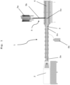
- Fig. 1 shows a first embodiment of a device 1 according to the present invention with an inlet port 5 that enters into a cooling die 4.
- the device 1 comprises an extruder 2 with barrel housings 2a (in the embodiment in Fig. 1 , 8 barrel housings are shown, but the extruder of the present invention is not limited to this number of barrel housings).
- the extruder 2 according to the embodiment of Fig. 1 furthermore comprises a gas inlet 2b with a gas storage container such as a pressurized bottle and a line through which gas can be led from said gas storage container into an extruder barrel housing 2a.
- a gas inlet 2b is not necessary (for any of the embodiments of Figs. 1 to 4 ), since the present invention also comprises embodiments where gas is generated in the extruder by other means, or no gas is provided in the extruder at all.
- a distributor unit 3 which provides for distribution of the extrudate flow from the extruder exit 2c into flows channels of the cooling die 4 that is arranged downstream of the distributor unit 3.
- the cooling die 4 may comprise one or more flow channels, preferably one annular flow channel in the cylindrical wall of the cooling die 4.
- an inlet port 5 that comprises a vessel 5a in which cellular material can be stored or preferably a dispersion such as a slurry, more preferably a concentrated slurry of cellular material can be formed.
- a line 5b leads into the cooling die 4 for conveying the cellular material into the cooling die 4.
- the line 5b is connected to the cooling die 4 via a plurality of, for example 5-10 openings that are combined in a single unit 5c that can be connected around the circumference of the cylindrical cooling die 4 that allows uniform insertion of the cellular material into the flow channels of the cooling die 4.
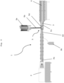
- Fig. 2 shows a second embodiment of a device 1 according to the present invention. Said embodiment differs from the embodiment of Fig. 1 in that the inlet port 5 is connected with and leads into the distributor unit 3.
- the connection is such that the cellular material is conveyed into the distributor unit 3 and therein uniformly distributed to the flow channels in the cooling die 4.
- the cellular material is conveyed into the distributor unit 3 at a point before distribution of the extrudate occurs.
- a heat exchange unit 2d (such as shown in Fig. 5a ) is provided upstream of the co-extrusion die, so as to allow cooling of the extrudate from the extruder barrel housings before it enters the co-extrusion die 5d. In such way, damage of the cellular material entering the co-extrusion die 2d from the inlet port 5 can be prevented.
- Fig. 4 shows a fourth embodiment of a device 1 according to the present invention.
- Said embodiment differs from the embodiments of Figs. 1 to 3 in that the inlet port 5 is connected with and leads into a last barrel housing of the extruder 2, which is designated as inlet barrel housing 2e.
- inlet barrel housing 2e a last barrel housing of the extruder 2, which is designated as inlet barrel housing 2e.
- a screw configuration is provided in said inlet barrel housing 2e that minimizes any shear force exerted on the material in said inlet barrel housing 2e. This can be realized, for example, by the screw configuration shown in Fig. 5b .
- a significant amount of heat may be generated, and said heat may cause damage on cellular material to be inserted through the inlet port 5.
- the provision of a heat exchange unit 2d in a region before the cellular material enters through the inlet port 5 serves for cooling the extrudate to a level that is acceptable for cellular material.
- the heat exchanger 2d is a shell-and-tube heat exchanger, in particular a tubular heat exchangers.
- the material is led from a first side of the heat exchanger through a cylindrical section with narrow channels to a second side of the heat exchanger, and thereby subjected to a homogeneous heat or cooling treatment.
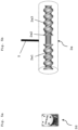
- Fig. 5b shows an embodiment of a screw arrangement at the location of the inlet port 5 in the embodiment of the device 1 shown in Fig. 4 .
- Said screw arrangement is thus provided in the last barrel housing of the extruder, which is designated as inlet barrel housing 2e.
- the screw arrangement comprises screw elements 2e1 that are located upstream the inlet port 5 and provide for kneading under high shear rates.
- screw elements 2e2 are arranged that provide for gentle mixing and conveying, but do not provide for a high shear rate.
- a polygon disks is shown in Fig. 5b . Since the shear rate also depends on the process conditions such as throughput speed and screw speed applied in the extruder, under varying conditions different screw elements may be suitable. In principle, any screw element may be used in that region that does not damage cellular material inserted in said region.
- screw elements 2e3 Downstream the section where the inlet port 5 enters into the inlet barrel housing 2e, only screw elements 2e3 are arranged that provide for gentle conveying, but do not provide for a high shear rate.
- Fig. 6 shows an embodiment of a system 12 according to the present invention.
- Said system 12 comprises a device 1 according to the present invention, preferably a device as shown in any of Figs. 1 to 4 , and additional units 6 to 11 discussed below. It is noted, however, that the sequence in which the units 6 to 11 are arranged in the embodiment of Fig. 6 is not compulsory and may be modified depending on specific requirements or preferences.
- a cutting unit 6 is arranged directly at the exit of the cooling die of the device 1.
- the cut material is then conveyed via a conveying unit 7a such as a conveyor belt to a cooling unit 8 where the material is further cooled.
- the cooling unit may be as discussed above a unit through with the material is conveyed and experiences a temperature gradient. However, the cooling unit could also be a nozzle that is arranged above the conveying unit 7a.
- the cooled material is then conveyed via a conveying unit 7b such as a conveyor belt to an injection unit 9.
- a conveying unit 7b such as a conveyor belt
- additional components may be injected into the material, preferably via needles.
- an injection unit 9 is preferred if in addition to the cellular material that it inserted into the extrudate through the inlet port of the device of the present invention, further components should be added. Those further components may be additional cellular material, flavoring components, nutrients (e.g. vitamins), or other additives commonly used for food products.
- the material is then conveyed via a conveying unit 7c such as a conveyor belt to an incubation unit 10.
- the cellular material in the extrudate may be cultivated to a desired state.
- incubation may be carried out under conditions that permit growth of cells in the extrudate.
- the material is then conveyed via a conveying unit 7d such as a conveyor belt to a finishing unit 11.
- Finishing units for finishing an extrudate are also known in the art. Such units may provide for marinating, enrobing or encasing a product, for example.
Landscapes
- Life Sciences & Earth Sciences (AREA)
- Chemical & Material Sciences (AREA)
- Engineering & Computer Science (AREA)
- Health & Medical Sciences (AREA)
- Food Science & Technology (AREA)
- Polymers & Plastics (AREA)
- Nutrition Science (AREA)
- Biochemistry (AREA)
- Molecular Biology (AREA)
- Manufacturing & Machinery (AREA)
- Formation And Processing Of Food Products (AREA)
- Extrusion Moulding Of Plastics Or The Like (AREA)
Priority Applications (11)
| Application Number | Priority Date | Filing Date | Title |
|---|---|---|---|
| EP21211396.3A EP4186371A1 (fr) | 2021-11-30 | 2021-11-30 | Produit alimentaire, dispositif et son procédé de fabrication |
| EP22156034.5A EP4186372A1 (fr) | 2021-11-30 | 2022-02-10 | Produit imitant les propriétés de la viande, de la volaille, du poisson, des fruits de mer ou des produits qui en sont dérivés, et procédé pour sa fabrication |
| EP22161130.4A EP4186373A1 (fr) | 2021-11-30 | 2022-03-09 | Dispositif et procédé de formation d'un produit imitant les propriétés de la viande, de la volaille, du poisson, des fruits de mer, des produits laitiers ou des produits qui en sont dérivés |
| CA3238667A CA3238667A1 (fr) | 2021-11-30 | 2022-11-28 | Produit alimentaire, et dispositif et procede pour sa production |
| CN202280079423.XA CN118368989A (zh) | 2021-11-30 | 2022-11-28 | 食物产品以及用于制造所述食物产品的装置和方法 |
| IL312825A IL312825A (en) | 2021-11-30 | 2022-11-28 | Food product and device and method for manufacturing the same |
| MX2024006511A MX2024006511A (es) | 2021-11-30 | 2022-11-28 | Producto alimenticio y dispositivo y metodo de fabricacion del mismo. |
| US18/713,412 US20250194637A1 (en) | 2021-11-30 | 2022-11-28 | Food product and device and method for manufacturing the same |
| KR1020247021017A KR20240108530A (ko) | 2021-11-30 | 2022-11-28 | 식품 및 이를 제조하기 위한 장치 및 방법 |
| PCT/EP2022/083511 WO2023099413A1 (fr) | 2021-11-30 | 2022-11-28 | Produit alimentaire, et dispositif et procédé pour sa production |
| AU2022403080A AU2022403080A1 (en) | 2021-11-30 | 2022-11-28 | Food product and device and method for manufacturing the same |
Applications Claiming Priority (1)
| Application Number | Priority Date | Filing Date | Title |
|---|---|---|---|
| EP21211396.3A EP4186371A1 (fr) | 2021-11-30 | 2021-11-30 | Produit alimentaire, dispositif et son procédé de fabrication |
Publications (1)
| Publication Number | Publication Date |
|---|---|
| EP4186371A1 true EP4186371A1 (fr) | 2023-05-31 |
Family
ID=78820012
Family Applications (1)
| Application Number | Title | Priority Date | Filing Date |
|---|---|---|---|
| EP21211396.3A Pending EP4186371A1 (fr) | 2021-11-30 | 2021-11-30 | Produit alimentaire, dispositif et son procédé de fabrication |
Country Status (9)
| Country | Link |
|---|---|
| US (1) | US20250194637A1 (fr) |
| EP (1) | EP4186371A1 (fr) |
| KR (1) | KR20240108530A (fr) |
| CN (1) | CN118368989A (fr) |
| AU (1) | AU2022403080A1 (fr) |
| CA (1) | CA3238667A1 (fr) |
| IL (1) | IL312825A (fr) |
| MX (1) | MX2024006511A (fr) |
| WO (1) | WO2023099413A1 (fr) |
Families Citing this family (2)
| Publication number | Priority date | Publication date | Assignee | Title |
|---|---|---|---|---|
| FR3112669B1 (fr) * | 2020-07-21 | 2024-07-12 | Clextral | Filière pour l’extrusion d’une matière riche en protéines et en eau, ainsi que machine d’extrusion comportant une telle filière |
| EP4635303A1 (fr) | 2024-04-19 | 2025-10-22 | Bühler AG | Buse de refroidissement pour extrudeuse |
Citations (8)
| Publication number | Priority date | Publication date | Assignee | Title |
|---|---|---|---|---|
| US7045160B1 (en) * | 1998-09-15 | 2006-05-16 | Dsm N.V. | Mucorales fungi for use in preparation of foodstuffs |
| WO2012158023A1 (fr) | 2011-05-13 | 2012-11-22 | Ojah B.V. | Procédé de fabrication de compositions texturées à base de protéines |
| US20180064137A1 (en) * | 2015-03-20 | 2018-03-08 | Nestec S.A. | A process for preparing a meat-analogue food product |
| US10028516B2 (en) * | 2015-07-17 | 2018-07-24 | Wenger Manufacturing, Inc. | Apparatus and method for processing of high meat content food or feed products |
| WO2018189738A1 (fr) | 2017-04-09 | 2018-10-18 | Supermeat The Essence Of Meat Ltd. | Aliment hybride contenant de la viande de culture |
| US20190364925A1 (en) * | 2018-06-04 | 2019-12-05 | Verso Food Oy | Method for manufacturing a food product |
| WO2020079440A1 (fr) * | 2018-10-17 | 2020-04-23 | Plant Meat Ltd | Produit et procédé de remplacement d'aliments |
| WO2021032866A1 (fr) | 2019-08-20 | 2021-02-25 | Bühler AG | Procédé de production d'aliments contenant des protéines |
-
2021
- 2021-11-30 EP EP21211396.3A patent/EP4186371A1/fr active Pending
-
2022
- 2022-11-28 CA CA3238667A patent/CA3238667A1/fr active Pending
- 2022-11-28 IL IL312825A patent/IL312825A/en unknown
- 2022-11-28 US US18/713,412 patent/US20250194637A1/en active Pending
- 2022-11-28 MX MX2024006511A patent/MX2024006511A/es unknown
- 2022-11-28 CN CN202280079423.XA patent/CN118368989A/zh active Pending
- 2022-11-28 AU AU2022403080A patent/AU2022403080A1/en active Pending
- 2022-11-28 WO PCT/EP2022/083511 patent/WO2023099413A1/fr not_active Ceased
- 2022-11-28 KR KR1020247021017A patent/KR20240108530A/ko not_active Withdrawn
Patent Citations (8)
| Publication number | Priority date | Publication date | Assignee | Title |
|---|---|---|---|---|
| US7045160B1 (en) * | 1998-09-15 | 2006-05-16 | Dsm N.V. | Mucorales fungi for use in preparation of foodstuffs |
| WO2012158023A1 (fr) | 2011-05-13 | 2012-11-22 | Ojah B.V. | Procédé de fabrication de compositions texturées à base de protéines |
| US20180064137A1 (en) * | 2015-03-20 | 2018-03-08 | Nestec S.A. | A process for preparing a meat-analogue food product |
| US10028516B2 (en) * | 2015-07-17 | 2018-07-24 | Wenger Manufacturing, Inc. | Apparatus and method for processing of high meat content food or feed products |
| WO2018189738A1 (fr) | 2017-04-09 | 2018-10-18 | Supermeat The Essence Of Meat Ltd. | Aliment hybride contenant de la viande de culture |
| US20190364925A1 (en) * | 2018-06-04 | 2019-12-05 | Verso Food Oy | Method for manufacturing a food product |
| WO2020079440A1 (fr) * | 2018-10-17 | 2020-04-23 | Plant Meat Ltd | Produit et procédé de remplacement d'aliments |
| WO2021032866A1 (fr) | 2019-08-20 | 2021-02-25 | Bühler AG | Procédé de production d'aliments contenant des protéines |
Non-Patent Citations (1)
| Title |
|---|
| VERBEKE ET AL., JOURNAL OF INTEGRATIVE AGRICULTURE, vol. 14, no. 2, 2015, pages 285 - 294 |
Also Published As
| Publication number | Publication date |
|---|---|
| MX2024006511A (es) | 2024-08-15 |
| WO2023099413A1 (fr) | 2023-06-08 |
| KR20240108530A (ko) | 2024-07-09 |
| IL312825A (en) | 2024-07-01 |
| CN118368989A (zh) | 2024-07-19 |
| AU2022403080A1 (en) | 2024-05-30 |
| US20250194637A1 (en) | 2025-06-19 |
| CA3238667A1 (fr) | 2023-06-08 |
Similar Documents
| Publication | Publication Date | Title |
|---|---|---|
| US12150463B2 (en) | Method for the production of protein-containing foods | |
| US20250194637A1 (en) | Food product and device and method for manufacturing the same | |
| US10798950B2 (en) | System and method for producing an extruded protein product | |
| US4614489A (en) | Simultaneous extrusion of multiple streams of a fibrous food product | |
| EP2908659B1 (fr) | Produit à mâcher pour animaux de compagnie, aéré et moulé par injection | |
| JP2017503476A (ja) | 同心対称分岐熱交換システム | |
| CN106136156A (zh) | 一种奇亚籽玫瑰花草莓功能型低糖果酱及其制备方法 | |
| US6001402A (en) | Preparation of a multi-colored food product with a process which includes extrusion | |
| CA2295937A1 (fr) | Procede et dispositif de fabrication de fromage a pate molle et a caille plastique a faible teneur en matieres grasses | |
| US6358547B1 (en) | Preparation of multi-colored products with a process which includes extrusion | |
| Çelekli et al. | Effect of Arthrospira platensis on physicochemical, texture, and microstructure properties of low-density marshmallows | |
| CS401091A3 (en) | Process for treating a cheese with a liquid | |
| US20250380728A1 (en) | High-moisture-extruded comestible cell-based food products | |
| RU2592619C1 (ru) | Способ производства хлебобулочных изделий | |
| Amertaningtyas et al. | Quality Characteristics of Marshmallow Candy Made with Beef Bone Gelatin and Powdered Cream Milk: Texture, Water Content, Aw, and pH | |
| HK40020245A (en) | System and method for producing an extruded protein product | |
| HK40020245B (en) | System and method for producing an extruded protein product |
Legal Events
| Date | Code | Title | Description |
|---|---|---|---|
| PUAI | Public reference made under article 153(3) epc to a published international application that has entered the european phase |
Free format text: ORIGINAL CODE: 0009012 |
|
| STAA | Information on the status of an ep patent application or granted ep patent |
Free format text: STATUS: THE APPLICATION HAS BEEN PUBLISHED |
|
| AK | Designated contracting states |
Kind code of ref document: A1 Designated state(s): AL AT BE BG CH CY CZ DE DK EE ES FI FR GB GR HR HU IE IS IT LI LT LU LV MC MK MT NL NO PL PT RO RS SE SI SK SM TR |
|
| STAA | Information on the status of an ep patent application or granted ep patent |
Free format text: STATUS: REQUEST FOR EXAMINATION WAS MADE |
|
| 17P | Request for examination filed |
Effective date: 20231108 |
|
| RBV | Designated contracting states (corrected) |
Designated state(s): AL AT BE BG CH CY CZ DE DK EE ES FI FR GB GR HR HU IE IS IT LI LT LU LV MC MK MT NL NO PL PT RO RS SE SI SK SM TR |
|
| P01 | Opt-out of the competence of the unified patent court (upc) registered |
Free format text: CASE NUMBER: APP_9388/2025 Effective date: 20250225 |