EP4186407B1 - Liquid sprayer for a dishwasher and dishwasher - Google Patents
Liquid sprayer for a dishwasher and dishwasher Download PDFInfo
- Publication number
- EP4186407B1 EP4186407B1 EP21210399.8A EP21210399A EP4186407B1 EP 4186407 B1 EP4186407 B1 EP 4186407B1 EP 21210399 A EP21210399 A EP 21210399A EP 4186407 B1 EP4186407 B1 EP 4186407B1
- Authority
- EP
- European Patent Office
- Prior art keywords
- arm
- spray arm
- drive
- liquid sprayer
- drive arm
- Prior art date
- Legal status (The legal status is an assumption and is not a legal conclusion. Google has not performed a legal analysis and makes no representation as to the accuracy of the status listed.)
- Active
Links
Images






Classifications
-
- A—HUMAN NECESSITIES
- A47—FURNITURE; DOMESTIC ARTICLES OR APPLIANCES; COFFEE MILLS; SPICE MILLS; SUCTION CLEANERS IN GENERAL
- A47L—DOMESTIC WASHING OR CLEANING; SUCTION CLEANERS IN GENERAL
- A47L15/00—Washing or rinsing machines for crockery or tableware
- A47L15/14—Washing or rinsing machines for crockery or tableware with stationary crockery baskets and spraying devices within the cleaning chamber
- A47L15/18—Washing or rinsing machines for crockery or tableware with stationary crockery baskets and spraying devices within the cleaning chamber with movably-mounted spraying devices
- A47L15/22—Rotary spraying devices
- A47L15/23—Rotary spraying devices moved by means of the sprays
Definitions
- the invention relates to a liquid sprayer for a dishwasher.
- the invention further relates to a dishwasher with a liquid sprayer.
- WO 2020/057821 A1 discloses a dishwasher with a liquid sprayer that comprises a first arm, which is rotatably mounted to a base body, and a second arm, which is rotatably mounted to the first arm.
- a transmission device couples the rotational movement of both arms. It is a disadvantage that food residues or increasing calcification can easily block the rotating movement of such a liquid sprayer and that the eccentric bearing of the spray arm causes vibrations.
- An object of the present invention is to provide an enhanced liquid sprayer, which is particularly reliable in application and particularly time, water and energy saving.
- a liquid sprayer having the features set out in claim 1. It was found according to the invention, that a liquid sprayer comprising a drive arm, a spray arm and a transmission device, which couples the rotational movement of the drive arm and the spray arm, is particularly reliable in application as well as time, water and energy saving, when the drive arm comprises at least one drive nozzle for driving the drive arm in rotation about the base axis and when the transmission device is configured such that a drive arm rotation rate is in absolute value at minimum as large as a spray arm rotation rate.
- the rotation rates of the drive arm and the spray arm are determined in a stationary coordinate system.
- the base body is rigidly fixed to that stationary coordinate system.
- the rotation rate can be specified in revolutions per second.
- the drive arm rotation rate is determined by the drive arm's speed of rotation about the base axis.
- the spray arm rotation rate is determined by the spray arm's speed of rotation about the spray arm axis. That the drive arm rotation rate and the spray arm rotation rate are compared in absolute values means that the direction of rotation should not be taken into account, only the rotation rate.
- the rotational movement, in particular the rotation rate, of the spray arm and of the drive arm are coupled linearly to each other, such there is a linear dependency between both rotation rates.
- the drive nozzle for driving the drive arm is preferably a nozzle for ejecting washing water. The drive nozzle can be aligned such that the ejection of the washing water results in a drive torque on the drive arm about the base axis.
- the transmission device is configured such that the drive arm rotation rate is at least as large as the spray arm rotation rate, the drive torque which is applied to the drive arm, causes a spray arm torque, which is at least as large as the drive torque.
- a spray arm torque which is at least as large as the drive torque.
- particularly high spray arm torques can be achieved. Due to this increased spray arm torque, the rotational movement of the liquid sprayer is more robust against soiling and calcination.
- the liquid sprayer is particularly reliable in use. Due to reliably dispensing the washing water uniformly, the liquid sprayer is particularly time, water and energy saving. The reduced rotational speed of the spray arm, especially when supported eccentrically to the base axis, results in reduced vibrations and a longer service life of the liquid sprayer.
- the liquid sprayer particularly the drive arm and/or the spray arm, are driven in rotation solely by means of drive nozzles for ejecting washing water.
- the drive arm and/or the spray arm preferably comprise at least one, particularly at least two, particularly at least three, and/or at most six, particularly at most five, drive nozzles.
- only the drive arm comprises the at least one drive nozzle. Due to avoiding motors, particularly electric motors and/or fluidic motors, for driving the liquid sprayer, particularly the spray arm, the complexity of the liquid sprayer can be further reduced. Such liquid sprayer is particularly robust in use and can be manufactured economically.
- the at least one drive nozzle sprays the liquid in the direction of a spray vector.
- the spray vector preferably comprises, in particular consists of, a radial and/or a tangential and/or an axial vector component with respect to the base axis.
- An angle between the axial direction, which is parallel to the base axis, and a vector consisting of the tangential and the axial vector components of the spray vector can be 30° to 150°, particularly 60° to 120°, particularly 75° to 105°, particularly 90°.
- An angle between the axial direction, which is parallel to the base axis, and a vector consisting of the radial and the axial vector components of the spray vector is preferably at most 30°, in particular 10°.
- the radial vector component of the spray vector is zero.
- the spray vector of the at least one drive nozzle can be aligned to spray out liquid towards a carrier for dishes.
- the base axis and/or the spray arm axis preferably enclose an angle with the vertical or the horizontal direction of at most 30°, particularly of at most 20°, particularly of at most 10°. More preferably, the base axis and/or the spray arm axis are aligned vertically or horizontally.
- the transmission device is configured such that there is a constant or a non-constant transmission rate between the drive arm rotation rate and the spray arm rotation rate.
- the transmission device comprises a gearbox.
- a non-constant transmission rate can for example be achieved by gear wheels with a non-circular shape, particularly regarding its gear rim.
- a gearbox with gear wheels that have a circular shape can be used to achieve a constant transmission ratio.
- the transmission ratio is specified by the ratio between the drive arm rotation rate and the spray arm rotation rate, particularly in the stationary coordinate system.
- the transmission ratio preferably is in the range from -1:1 to +1:1, more preferably from more than -1:1 to less than 1:1, more preferably from -1:3 to 1:3, more preferably from -1:5 to 1:5.
- the base axis and the spray arm axis are spaced apart from each other.
- the base axis and the spray arm axis preferably are aligned parallel and/or in a vertical direction.
- the spray arm preferably comprises at least one, particularly at least two, particularly at least three, and/or at most four, particularly at most three, spray booms.
- the at least two spray booms are preferably aligned perpendicular to the spray arm axis.
- the spray booms can have different lengths perpendicular to the spray arm axis, particularly when the spray arm comprises two spray booms. Thus, a particularly uniform distribution of washing water can be achieved.
- the transmission device is configured such that the motion path of the spray arm is identical for each of its revolutions, particularly about the spray arm axis.
- the transmission ratio is preferably one of the values -1:3, 1:5 or 1: 1.
- the washing water is thereby distributed in the dishwasher, particularly in a washing chamber with a rectangular, particularly square, base shape, more evenly.
- the motion paths are also referred to as trajectories.
- the trajectories of the at least one spraying nozzle and/or the at least one drive nozzle are identical for each revolution of the drive arm and/or the spray arm.
- the transmission device is preferably a gearbox with at least two gear wheels. Such transmission device is economic to manufacture and robust in use.
- the base body preferably at least in sections is rotationally fixed, preferably completely fixed, to the washing chamber of the dishwasher.
- the base body can comprise a drain sump and/or a drain grid and/or a supply socket for conducting washing water to the liquid sprayer and/or a gear wheel, particularly a base gear wheel, of the transmission device.
- the liquid sprayer is preferably configured to be reversibly attached to the base body.
- the base body can be reversibly attached to the washing chamber and/or to the supply socket or be of one piece with them. Due to the reversible attachment of the liquid sprayer to the base body and/or of the base body to the washing chamber, the liquid sprayer is particularly easy to install or to replace.
- a liquid sprayer as claimed in claim 2 is particularly robust in use.
- the drive arm rotation rate is in absolute value at least two times larger, more preferably at least three times larger, more preferably at least four times larger, than the spray arm rotation rate.
- the resulting drive arm torque can be increased further.
- a liquid sprayer as claimed in claim 3 is particularly robust and durable. Due to the rotation of the drive arm and the spray arm in opposite directions, particularly with reference to the stationary coordinate system, bearing loads and/or vibrations can be reduced. Due to the counter rotation of the drive arm and the spray arm, their rotation rates can be reduced, while the transmission ratio can be set to at most one in absolute value. The reduced rotation rates lead to decreased centrifugal forces and thus reduced bearing loads and vibrations.
- the transmission device is preferably configured to provide a transmission ratio of less than 0.
- a liquid sprayer as claimed in claim 4 can be manufactured particularly economical and is robust in use.
- a base gear wheel is part of the base body and/or attached to it in a rotationally fixed manner.
- the base gear wheel and the base body can be one piece.
- a spray arm gear wheel is preferably rigidly attached to the spray arm and/or integrally connected with it.
- the third gear wheel is preferably a drive gear wheel, which is attached to the drive arm such that it can rotate relative to the drive arm, in particular about a drive shaft axis.
- the drive shaft axis, the base axis and/or the spray arm axis are preferably spaced apart from each other and/or aligned parallel, in particular parallel to a vertical direction.
- the transmission device preferably comprises at least three, more preferably at least four, more preferably at least five, and/or at most six, particularly at most five, interlocking gear wheels.
- the interlocking gear wheels can comprise straight-toothed gear wheels and/or helical gear wheels. Helical gear wheels are particularly robust in use and reduce vibrations.
- the transmission device is preferably configured such that it is not self-locking.
- the transmission device preferably solely comprises gear wheels with cylindrical, particularly circular cylindrical, gear rims.
- the liquid sprayer as claimed in claim 5 can be maintained easily and is particularly compact.
- at least one, more preferably at least two, more preferably all, of the gear wheels are located outside the liquid duct and/or a hollow structure of the drive arm and/or of the spray and/or outside a housing of the liquid sprayer, in particular of the drive arm and/or of the spray arm.
- the at least one gear wheel can be located such that it is wetted by the washing water, which is dispensed in the washing chamber, particularly by means of the liquid sprayer. Thereby, the liquid sprayer can be dimensioned more compact. Further, the gear wheels are lubricated by the washing water.
- the at least one gear wheel is detachably mounted.
- it can be installed and/or replaced easily, in particular when it is located outside the liquid duct, in particular outside a housing of the liquid sprayer.
- a liquid sprayer as claimed in claim 6 is particularly flexible, robust and economic in use.
- a first drive gear wheel and a second drive gear wheel are rigidly connected together, preferably by means of a drive shaft.
- Those drive gear wheels can be rotatably mounted to the drive arm.
- the first and the second drive gear wheel are attached to the drive arm such that it can rotate about the drive shaft axis. Due to the four interlocking gear wheels, the washing water can be dispensed within the washing chamber more uniformly.
- at least one of the drive gear wheels are replaceable.
- different transmission ratios can be achieved, which allow for the use of the liquid sprayer for dishwashers with different washing chamber geometries, particularly with a different base shape.
- the first drive gear wheel and the second drive gear wheel preferably have the same number of teeth. Alternatively, they can comprise different numbers of teeth.
- the base gear wheel and the spray arm gear wheel can have the same number of teeth or a different number of teeth. According to an aspect of the invention, the number of teeth of the drive gear wheels is less than the number of teeth of the base gear wheel and/or the spray arm gear wheel.
- the base gear wheel interlocks with the first drive gear wheel.
- the first drive gear wheel and the second drive gear wheel are rigidly connected to each other, particularly via a drive shaft.
- the drive gear wheels are supported at the drive arm rotatably.
- the drive shaft is preferably attached to the drive arm such that it can rotate about a drive shaft axis.
- the second drive gear wheel interlocks with the spray arm gear wheel.
- the transmission ratio can be calculated depending on the number of teeth of the base gear wheel n B , of the first drive gear wheel n D1 , of the second drive gear wheel n D2 and of the spray arm gear wheel ns according to the following formulas
- a liquid sprayer as claimed in claim 7 is particularly flexible in use.
- a pinion preferably comprises the two drive gear wheels and a drive shaft at which the drive gear wheels are attached.
- the pinion is preferably attached to a pinion bearing such that it can rotate about the drive shaft axis, particularly relative to the pinion bearing.
- the pinion bearing is preferably reversibly attached to the liquid sprayer, particularly to the drive arm.
- a non-destructive connection in particular a snap-in-connection, can be used.
- the drive gear wheels in particular the pinion can be designed such that their strength is lower than the strength of the remaining parts of the transmission device.
- the pinion can be designed in the form of a predetermined breaking point, which can easily be replaced.
- a liquid sprayer as claimed in claim 8 is particularly flexible in use. Since the number of teeth of the rigidly connected gear wheels are different, an increased drive torque at the drive arm can be achieved. Further, multiple different transmission ratios can be set, depending on the ratio of teeth of the two gear wheels.
- a liquid sprayer as claimed in claim 9 is particularly economical in use.
- the non-circular, preferably elliptical, more preferably oval shape of the at least one, more preferably at least two, more preferably at least three, even more preferably at least four, gear wheels allow for a motion path of the liquid sprayer, particularly its nozzles, which better fits the shape of the washing chamber, particularly its base shape.
- interlocking gear pairs have such a shape.
- the axes of rotation of such wheels can thus be arranged at a constant distance from each other.
- Such transmission device allows for a rectangular, particularly non-square, shape of the motion path of the at least one spraying nozzle.
- a liquid sprayer as claimed in claim 10 ensures for a proper installation of the liquid sprayer.
- the liquid sprayer preferably, comprises alignment means.
- alignment means preferably comprise a form-fitting means, which reversibly locks the spray arm and/or the drive arm to the base body, particularly with regard to the rotational movement, particularly in a predefined alignment.
- a locked liquid sprayer can be installed into the washing chamber easily, without the danger of misalignment.
- the form fitting means preferably comprise a drive arm through hole, a spray arm through hole and an alignment receiver, which is preferably rigidly attached to the base body.
- a detachable alignment means preferably in the form of a bolt, can be inserted through the drive arm through hole and the spray arm through hole into the alignment element receiver, preferably in the direction of the base axis and/or the spray arm axis and/or the drive shaft axis, such that the drive arm and the spray arm are locked to the base element.
- a liquid sprayer as claimed in claim 11 is particularly easy and economic to install.
- the alignment means preferably comprise the optical means.
- the optical means can be designed in the form of an imprint or an embossing to the spray arm, to the drive arm and/or to the base arm. Such optical means help the assembler or the user to align the spray arm with the drive arm and/or with the base body.
- the orientation of the motion path of the liquid sprayer perfectly fits with the geometry of the washing chamber, particularly its base shape.
- a liquid sprayer as claimed in claim 12 to 14 is particularly easy to assemble, economic in manufacturing and robust in use.
- the drive arm and/or the spray arm comprise a liquid duct, in particular a hollow structure for conducting the washing liquid to the nozzles.
- the washing water is conducted into the spray arm via the drive arm, particularly via its hollow structure.
- the drive arm comprises a base connector, particularly a base sleeve, for attaching the drive arm to the base body, particularly to a supply socket that is attached to the washing chamber.
- the base connector preferably bears the drive arm rotatably about the base axis.
- the base sleeve preferably comprises a drive arm inflow through which the washing water is conducted into the drive arm.
- the drive arm preferably further comprises a spray arm sleeve to which the spray arm is attached rotatably.
- the spray arm sleeve determines the spray arm axis.
- a spray arm connector of the spray arm preferably comprises a spray arm socket, which can be attached to the spray arm sleeve of the drive arm.
- the spray arm socket preferably determines a spray arm inflow through which the washing water is conducted into the spray arm. Since the base axis intersects the drive arm inflow and/or the spray arm axis intersects the spray arm inflow, the washing water can be conducted to the drive arm and/or to the spray arm, particularly through the drive arm, in a particularly robust manner.
- Such liquid sprayer is further economic in manufacturing and easy to assemble.
- a further aspect of the present invention is to provide an enhanced dishwasher, which is particularly robust as well as time, water and energy saving in use.
- the dishwasher is further improved with at least one feature disclosed with reference to the liquid sprayer described above.
- the base body can be a part of the dishwasher, particularly of its washing chamber and/or its sump.
- the base body can be designed as part of the liquid sprayer, which is reversibly attachable to the dishwasher, particularly to the washing chamber and/or the sump.
- the dishwasher preferably comprises an attachment means, to which the base body can be mounted, particularly in a rotationally fixed manner, particularly about the base axis.
- Such attachment means is preferably the supply socket for supplying the washing water to the liquid sprayer.
- the dishwasher preferably comprises at least one dish basket, preferably two dish baskets.
- the dishwasher preferably comprises at least one, more preferably at least two, of the liquid sprayers.
- the at least one liquid sprayer is preferably located below the at least one dish basket, particularly at the bottom of the washing chamber and/or below an upper one of the dish baskets.
- the base shape of the washing chamber is, according to an aspect of the invention, polygonal, particularly rectangular, particularly square or non-square.
- the base shape of the washing chamber preferably is designed with an aspect ratio of almost 1:1 or at least 6:5, preferably at least 5:4, , more preferably at least 4:3, more preferably at least 3:2, more preferably at least 2:1.
- the base shape of the washing chamber is specified by its outline in a top view. Edge and corner areas of the washing chamber are preferably neglected. In practice, they can be rounded off.
- the liquid sprayer described above allows for a particularly uniform distribution of washing water in a polygonal washing chamber.
- a dishwasher 1 according to a first embodiment as shown in fig. 1 to fig. 12 comprises a washing chamber 2, a sump 3 that is arranged at the bottom of the washing chamber 2 and a liquid sprayer 4 for dispensing liquid within the washing chamber 2.
- a washing chamber 2 In the washing chamber 2 two dish baskets 5a, 5b for carrying dishes 6 are arranged.
- the liquid sprayer 4 is located below the lower dish basket 5a.
- a second liquid sprayer 7 is located below the upper dish basket 5b.
- the dishwasher 1 further comprises a fluid management device 8 for providing the liquid sprayers 4, 7 with washing liquid, particularly washing water.
- the fluid management device 8 comprises at least one liquid pump for conveying the washing liquid and/or at least one valve for controlling the flow of the washing liquid. These are not shown in the figures.
- the washing chamber 2, the sump 3, the liquid sprayers 4, 7, the dish baskets 5a, 5b and the fluid management device 8 are located within a dishwasher housing 9.
- the dishwasher 1 comprises a fresh water port 10, through which fresh water is provided, and a drain water port 11, through which drain water is discharged.
- the fresh water port 10 and the drain water port 11 are connected to the fluid management device 8 via water ducts 12.
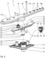
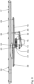
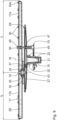
- the liquid sprayer 4 in fig. 1 is shown in more detail.
- the liquid sprayer 4 is attached to a base body 13.
- the base body 13 comprises a drain grid 14 for filtering large objects from the washing water to avoid them entering into the sump 2.
- the base body 13 further comprises a supply socket 15.
- the drain grid 14 and the supply socket 15 are one piece.
- the liquid sprayer 4 comprises a drive arm 16 and a spray arm 17.
- the drive arm 16 is mounted to the base body 13 so that it can rotate about a base axis 18.
- the spray arm 17 is mounted to the drive arm 16 so that it can rotate about a spray arm axis 19.
- the base axis 18 is determined by means of a base connector 20, which is part of the drive arm 16 and arranged for reversibly attaching the drive arm 16 to the base body 13.
- the base connector 20 is designed such that the drive arm 16 can freely rotate about the base axis 18 and such that washing water can be conducted liquid-tight between the supply socket 15 and the drive arm 16. Therefore, the base connector 20 comprises a base sleeve 21, which can be inserted in the supply socket 15.
- Two bearing rings 22 are attached to the base sleeve 21 and provide the rotatable bearing and the waterproof connection.
- the spray arm 17 comprises a spray arm connector 23 that is designed to connect the spray arm 17 to the drive arm 16 so that they can rotate relative to each other about the spray arm axis 19.
- the drive arm 16 comprises a spray arm sleeve 24, which can be plugged into a spray arm socket 25 of the spray arm connector 23.
- the spray arm sleeve 24 comprises two bearing rings 26.
- the drive arm 16 and the spray arm 17 comprise a hollow structure 27, 28.
- the hollow structure 27 of the drive arm 16 provides a fluid conducting connection between the base sleeve 21 and the spray arm sleeve 24. Via the spray arm socket 25, the fluid is conducted from the hollow structure 27 of the drive arm 16 into the hollow structure 28 of the spray arm 17. Thus, washing water, which is supplied via the supply socket 15, is conducted via the drive arm 16 into the spray arm 17.
- the drive arm 16 comprises two nozzles 29, in particular drive nozzles 29.
- the drive nozzles 29 are designed such that washing water sprayed out via the drive nozzles 29 causes a drive force F D , which leads to a drive torque M D about the base axis 18. Consequently, spraying out water via the drive nozzle 29 sets the drive arm 16 into rotation about the base axis 18.
- the spray arm 17 comprises at least one, in particular multiple, spraying nozzles 30, 30a.
- the spraying nozzles 30, 30a are preferably aligned to spray out the washing water in a direction that is parallel to the base axis 18 and/or the spray arm axis 19, particularly in the vertical direction. Since the liquid sprayer is arranged below the dish basket 5a, the dishes 6 within this dish basket 5a can be cleaned efficiently and reliably by means of the liquid sprayer 4.
- the spraying nozzle 30, 30a which is most distant from the spray arm axis 19, has the reference sign 30a.
- the spray arm 17 is eccentrically attached to the drive arm 16.
- the drive arm 16 has two spray booms 17a, 17b, a larger one 17a and a shorter one 17b.
- the dimension r L of the larger spray boom 17a of the spray arm 17 perpendicular to the spray arm axis 19 is 240 mm.
- the dimension rs of the smaller spray boom 17b of the spray arm 17 perpendicular to the spray arm axis 19 is 160 mm.
- the drive nozzles 29 is in fluid conducting connection with the hollow structure 27 of the drive arm 16.
- the spraying nozzles 30, 30a are in fluid conducting connection with the hollow structure 28 of the spray arm 17. Both types of nozzles 29, 30, 30a are supplied with washing water via the base sleeve 21, particularly via the supply socket 15.
- the liquid sprayer 4 comprises a transmission device 31, which couples the rotational movement of the drive arm 16 about the base axis 18 with the rotational movement of the spray arm 17 about the spray arm axis 19.
- the transmission device 31 is designed in the form of a gear transmission.
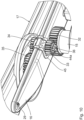
- the transmission device 31 comprises four gear wheels 32, 33, 34, 35.
- a base gear wheel 32 is rigidly connected to the supply socket 15.
- the base gear wheel 32 is part of the base body 13.
- the base gear wheel 32 interlocks with a first drive gear wheel 33 that is rotatably attached to the drive arm 16.
- a second drive gear wheel 34 is also attached to the drive arm 16 rotatably.
- the first drive gear wheel 33 and the second drive gear wheel 34 are rigidly connected to each other via a drive shaft 36.
- the drive shaft 36 is attached to the drive arm 16 such that it can rotate about a drive shaft axis 37.
- the second drive gear wheel 34 interlocks with a spray arm gear wheel 35 that is rigidly attached to the spray arm 17.
- the base gear wheel 32 and the supply socket 15 are formed in one piece.
- the spray arm gear wheel 35 and the spray arm 17 are also formed in one piece.
- the drive gear wheels 33, 34 and the drive shaft 36 can be formed in one piece.
- the part comprising the drive gear wheels 33, 34 and the drive shaft 36 is referred to as a pinion 38.
- the base gear wheel 32 is rigidly connected to the washing chamber 2, in particular also to the sump 3 and to the dishwasher housing 9.
- the transmission device 31 transforms the rotational motion of the drive arm 16 into a rotation of the pinion 38 with the two drive gear wheels 33, 34.
- the rotation of the second drive gear wheel 34 causes a rotation of the spray arm gear wheel 35 and thus of the spray arm 17 about the spray arm axis 19.
- a drive arm rotation rate ⁇ D is the rotation rate of the drive arm 16 in a stationary coordinate system 39, in particular about a vertical axis, particularly the base axis 18.
- a spray arm rotation rate ⁇ S is a rotation rate of the spray arm 17 in the stationary coordinate system 39, in particular about the vertical axis, particularly the spray arm axis 19 or the base axis 18.
- the transmission device 31 is configured such that a transmission ratio ⁇ between the spray arm rotation rate ⁇ S and the drive arm rotation rate ⁇ D is -1:3.
- the base axis 18, the spray arm axis 19 and the drive shaft axis 37 are aligned parallel and spaced apart from each other.
- the base sleeve 21 determines a drive arm inflow 40 for receiving the washing water.
- the spray arm sleeve 24 has a drive arm outflow 41 through which the washing water is transferred to the spray arm 17.
- the spray arm socket 25 determines a spray arm inflow 42 through which the washing water is received.
- the base axis 18 intersects the drive arm inflow 40.
- the supply socket 15 and/or the base sleeve 21 is at least in sections rotationally symmetrical to the base axis 18.
- the spray arm axis 19 preferably intersects the drive arm outflow 41 and/or the spray arm inflow 42.
- the spray arm sleeve 24 and/or the spray arm socket 25 are preferably at least in sections rotationally symmetrical to the spray arm axis 19.
- the water duct 12 within the liquid sprayer 4, in particular in the drive arm 16 and/or in the spray arm 17, is intersected by the base axis 18 and/or the spray arm axis 19.
- the pinion 38 is mounted to a pinion bearing 43.
- the pinion bearing 43 and the pinion 38 determine a reversibly detachable gear unit 44a.
- the gear unit 44a can be mounted to the drive arm 16 by means of a detachable connection 45, in particular a snap-fit-connection.
- the gear unit 44a is replaceable with alternative gear units 44b, which comprise drive gear wheels 33, 34 with a different number of teeth n B , n D1 , n D2 , n S .
- the transmission ratio ⁇ of the transmission device 31 can easily be amended.
- the detachable connection 45 is designed such that the drive shaft axis 37 of different gear units 44a can be located differently with reference to the position of the base axis 18 and/or the spray arm axis 19.
- the distance between the drive shaft axis 37 and the base axis 18 or the spray arm axis 19 can be adjusted to the particular number of teeth n D1 , n D2 of the drive gear wheels 33, 34, in particular without amending the design, particularly the number of teeth n B , ns of the base gear wheel 32 or the spray arm gear wheel 35.
- the liquid sprayer 4 comprises alignment means 46 for aligning the drive arm 16 with the spray arm 17 and the base body 13 in a specific orientation to each other.
- alignment means 46 comprise a drive arm through hole 47, a spray arm through hole 48 and at least one alignment element receiver 49 in the form of a through hole within the base body 13.
- the drive arm through hole 47, the spray arm through hole 48 and the alignment element receiver 49 are designed such that an alignment element 50, preferably in the form of a bolt can be pushed through all of these holes 47, 48, 49 in order to lock the orientation of the drive arm 16 and the spray arm 17 relative to the base body 13 in a predefined alignment.
- Such form-fitting means allow for a correct installation of the liquid sprayer 4 with regard to the base body 13 and the washing chamber 2 in a particularly reliable manner.
- the alignment means 46 comprise optical means not shown that indicate the correct orientation of the drive arm 16, the spray arm 17 and the base body 13 within the washing chamber 2.
- Such optical means preferably comprise signs, such as arrows, which point at each other or at a specific target, when the liquid sprayer 4 is properly aligned.
- the functionality of the dishwasher 1, in particular the liquid sprayer 4, is as follows: In an initial state, the dishwasher 1 is deactivated. The dishes 6 are deposited in the dish baskets 5a, 5b.
- the user selects a washing program and activates the dishwasher 1.
- the fluid management device 8 By means of the fluid management device 8, fresh water is conveyed into the washing chamber 2.
- the water is heated by means of the fluid management device 8 and repeatedly circulated from the sump 3 to the washing chamber 2.
- the washing water is conducted into the washing chamber 2 by means of the liquid sprayers 4, 7, which spread the washing water within the washing chamber 2.
- the washing water is conducted from the fluid management device 8 via the water duct 12 to the supply socket 15 and via the drive arm inflow 40 into the hollow structure 27 of the drive arm 16.
- the washing water is further conducted into the hollow structure 28 of the spray arm 17.
- the washing water is ejected through the nozzles 29 and 30, 30a.
- the motion of the nozzle 30a which is most distant to the spray arm axis 19, is shown.
- the motion path of this nozzle 30a has the reference sign 51a.
- the washing chamber 2 has a square base area, except for its edges. It can be seen from fig. 12 that the motion path 51a of the nozzle 38 fits perfectly to the square base. Washing water can be spread in the edge regions of the washing chamber 2, while a collision between the liquid sprayer 4 and the washing chamber walls is reliably avoided.
- the spray arm 17 and the drive arm 16 rotate in opposite directions with respect to the stationary coordinate system 39.
- the nozzle 30a reaches one of the four edges of the washing chamber 2 every 270 degrees of rotation of the drive arm 16 respectively every 90 degrees of rotation of the spray arm 17.
- the liquid sprayer 4 in particular the drive arm 16 and the spray arm 17, is driven by the drive force F D which results from ejecting washing water through the drive nozzles 29. Due to the fact that the transmission ratio ⁇ is in absolute value less than 1, the drive arm 16 rotates faster than the spray arm 17. In other words, the drive arm rotation rate ⁇ D is in absolute value larger than the spray arm rotation rate ⁇ S .
- the drive torque M D that is thereby applied to the drive arm 16 is multiplied by the transmission device 31 by the factor of the transmission ratio ⁇ .
- a spray arm torque Ms that drives the spray 17 in rotation about the spray arm axis 19 is thus three times as high as the drive torque M D .
- the liquid sprayer 4 is thus set in rotation in a particularly reliable manner.
- the dishes 6 are cleaned in a particularly reliable, time saving and energy efficient manner, due to the fact that the washing water is dispensed evenly and that the rotation of the spray arm is robust against dirt deposit and calcification.
- the gear unit 44a is detached from the drive 16.
- the drive arm 16 and the spray arm 17 are aligned such that the drive arm through hole 47, the spray arm through hole 48 and the alignment element receiver 49 overlap each other.
- the alignment element 40 can then be inserted through the through holes 47, 48 into the alignment receiver 49.
- the gear unit 44a can be attached to the drive arm 16 by just pushing it into the according gear unit reception 52.
- the gear unit 44a is secured to the drive arm 16 by means of the snap-fit-connection. Thereby, the drive arm 16 and the spray arm 17 are aligned properly with respect to the base body 32 and the washing chamber 2.
- the alignment element 50 has to be removed from the liquid sprayer 4 to unlock the rotation of the drive arm 16 and the spray arm 17 about the base axis 18 and the spray arm axis 19.
- the liquid sprayer 4 is properly aligned to the washing chamber 2 and the dishwasher 1 is ready for the next washing process.
- Fig. 13 shows a gear unit 44b that can be used with the liquid sprayer 4 as an alternative to the gear unit 44a in fig. 11 .
- the use of this gear unit 44b results in the motion path 51b of the spraying nozzle 30a shown in fig. 14 .
- Such motion path 51b has an elliptical, in particular an oval shape.
- Such an elliptically shaped motion path 5 1b is particularly advantageous for the use with a washing chamber 2 with a rectangular, non-square base shape.
- the liquid sprayer 4 can easily be adapted to dishwashers 1 with different washing chambers 2, in particular with different base shapes.
- the same drive arm 16 and spray arm 17 can be used for dishwashers 1 with different geometries while only the gear unit 44a, 44b has to be designed or selected accordingly. The manufacturing costs of the dishwasher 1 can thus be considerably reduced.
- Fig. 15 shows another embodiment of a liquid sprayer 4 according to the invention.
- the drive arm 16 comprises two drive nuzzles 29, which are aligned in a plane perpendicular to the base axis 18.
- the pinion bearing 43 and the drive arm 16 are one piece.
- the pinion 38 is thus not detachable from the drive arm 16.
- the base gear wheel 32 and the supply socket 15 are separate parts, which can be attached to each other by means of a snap-fit-connection.
- the dishwasher 1 can flexibly be equipped with either a conventional liquid sprayer 4 without a transmission device 31, particularly a base gear wheel 32, or with a liquid sprayer 4 according to the above described invention.
- the functionality of the liquid sprayer 4 in fig. 15 corresponds to the functionality of the aforementioned liquid sprayer 4.
- the gear wheels 32, 33, 34, 35 of the aforementioned embodiments have a circular shape.
- at least two interlocking gear wheels comprise a non-circular gear rim, in particular with an elliptical shape, more particular an oval shape.
- a motion path 51a, 51b can be achieved which even better fits to the base shape of the washing chamber 2.
- a more even distribution of washing water within a rectangular, particularly a non-square, washing chamber 2 can be achieved.
- the dishwasher 1 with the liquid sprayer 4 according to the invention can be used particularly flexible with differently shaped washing chambers 2. It allows for a cost saving manufacturing of the dishwasher. Further, a more uniform distribution of washing water within the washing chamber 2 can be achieved.
- the dishwasher 1 is particularly time, water and energy saving and durable.
Landscapes
- Washing And Drying Of Tableware (AREA)
- Nozzles (AREA)
Priority Applications (4)
| Application Number | Priority Date | Filing Date | Title |
|---|---|---|---|
| EP21210399.8A EP4186407B1 (en) | 2021-11-25 | 2021-11-25 | Liquid sprayer for a dishwasher and dishwasher |
| ES21210399T ES2985327T3 (es) | 2021-11-25 | 2021-11-25 | Pulverizador de líquido para lavavajillas y lavavajillas |
| PL21210399.8T PL4186407T3 (pl) | 2021-11-25 | 2021-11-25 | Spryskiwacz płynu do zmywarki i zmywarka do naczyń |
| PCT/EP2022/082974 WO2023094447A1 (en) | 2021-11-25 | 2022-11-23 | Liquid sprayer for a dishwasher and dishwasher |
Applications Claiming Priority (1)
| Application Number | Priority Date | Filing Date | Title |
|---|---|---|---|
| EP21210399.8A EP4186407B1 (en) | 2021-11-25 | 2021-11-25 | Liquid sprayer for a dishwasher and dishwasher |
Publications (3)
| Publication Number | Publication Date |
|---|---|
| EP4186407A1 EP4186407A1 (en) | 2023-05-31 |
| EP4186407C0 EP4186407C0 (en) | 2024-05-29 |
| EP4186407B1 true EP4186407B1 (en) | 2024-05-29 |
Family
ID=78789810
Family Applications (1)
| Application Number | Title | Priority Date | Filing Date |
|---|---|---|---|
| EP21210399.8A Active EP4186407B1 (en) | 2021-11-25 | 2021-11-25 | Liquid sprayer for a dishwasher and dishwasher |
Country Status (4)
| Country | Link |
|---|---|
| EP (1) | EP4186407B1 (pl) |
| ES (1) | ES2985327T3 (pl) |
| PL (1) | PL4186407T3 (pl) |
| WO (1) | WO2023094447A1 (pl) |
Families Citing this family (1)
| Publication number | Priority date | Publication date | Assignee | Title |
|---|---|---|---|---|
| FI20246066A1 (en) * | 2024-08-28 | 2026-03-01 | Teijo Pesukoneet Oy | Arrangement for spraying fluid, cleaning machine and method |
Citations (21)
| Publication number | Priority date | Publication date | Assignee | Title |
|---|---|---|---|---|
| US3876148A (en) | 1973-09-13 | 1975-04-08 | Gen Electric | Dishwasher having epicyclic spray system |
| JPH05130964A (ja) | 1991-11-14 | 1993-05-28 | Matsushita Electric Ind Co Ltd | 食器洗浄機 |
| JPH0631646U (ja) | 1992-09-25 | 1994-04-26 | 象印マホービン株式会社 | 食器洗浄機 |
| JPH0631647U (ja) | 1992-10-09 | 1994-04-26 | 象印マホービン株式会社 | 食器洗浄機 |
| JPH07236605A (ja) | 1994-03-01 | 1995-09-12 | Matsushita Electric Ind Co Ltd | 食器洗浄機 |
| US5464482A (en) | 1994-11-07 | 1995-11-07 | Maytag Corporation | Washarm assembly for dishwasher |
| KR20130011337A (ko) | 2011-07-21 | 2013-01-30 | 엘지전자 주식회사 | 식기 세척기 |
| US20170150866A1 (en) | 2015-11-30 | 2017-06-01 | Whirlpool Corporation | Spray arm for a dish treating appliance |
| CN106821252A (zh) | 2017-03-17 | 2017-06-13 | 佛山市顺德区美的洗涤电器制造有限公司 | 喷臂组件和具有其的洗碗机 |
| CN107028572A (zh) | 2016-12-13 | 2017-08-11 | 佛山市顺德区美的洗涤电器制造有限公司 | 用于洗碗机的喷臂装置及具有其的洗碗机 |
| CN206675493U (zh) | 2016-12-13 | 2017-11-28 | 佛山市顺德区美的洗涤电器制造有限公司 | 用于洗碗机的喷臂装置及具有其的洗碗机 |
| CN207152552U (zh) | 2017-03-17 | 2018-03-30 | 佛山市顺德区美的洗涤电器制造有限公司 | 喷臂组件和具有其的洗碗机 |
| EP3384821A1 (en) | 2015-12-01 | 2018-10-10 | Foshan Shunde Midea Washing Appliances Mfg. Co., Ltd. | Spraying arm assembly of dish washer and dish washer having same |
| EP3403564A1 (en) | 2017-05-16 | 2018-11-21 | Gorenje d.d. | Sprayer arrangement for a dishwasher |
| WO2019037995A1 (en) | 2017-08-25 | 2019-02-28 | Arcelik Anonim Sirketi | DISHWASHER WITH ENHANCED WASHING PERFORMANCE |
| WO2020036558A2 (en) | 2018-08-13 | 2020-02-20 | Arcelik Anonim Sirketi | A dishwasher with improved washing performance |
| WO2020057821A1 (en) | 2018-09-17 | 2020-03-26 | Arcelik Anonim Sirketi | A dishwasher having a plurality of spray arms |
| US10667668B2 (en) | 2013-06-27 | 2020-06-02 | Whirlpool Corporation | Dishwasher with rotationally mounted sprayer |
| KR20210069349A (ko) | 2019-12-03 | 2021-06-11 | 에스케이매직 주식회사 | 식기세척기용 로터 조립체 |
| EP3834696A1 (de) | 2019-12-12 | 2021-06-16 | Haier Deutschland GmbH | Flüssigkeitsausbringer zum ausbringen von spülflüssigkeit |
| EP3843604B1 (en) | 2018-08-31 | 2023-08-02 | Arçelik Anonim Sirketi | A dishwasher having improved washing performance |
-
2021
- 2021-11-25 EP EP21210399.8A patent/EP4186407B1/en active Active
- 2021-11-25 ES ES21210399T patent/ES2985327T3/es active Active
- 2021-11-25 PL PL21210399.8T patent/PL4186407T3/pl unknown
-
2022
- 2022-11-23 WO PCT/EP2022/082974 patent/WO2023094447A1/en not_active Ceased
Patent Citations (21)
| Publication number | Priority date | Publication date | Assignee | Title |
|---|---|---|---|---|
| US3876148A (en) | 1973-09-13 | 1975-04-08 | Gen Electric | Dishwasher having epicyclic spray system |
| JPH05130964A (ja) | 1991-11-14 | 1993-05-28 | Matsushita Electric Ind Co Ltd | 食器洗浄機 |
| JPH0631646U (ja) | 1992-09-25 | 1994-04-26 | 象印マホービン株式会社 | 食器洗浄機 |
| JPH0631647U (ja) | 1992-10-09 | 1994-04-26 | 象印マホービン株式会社 | 食器洗浄機 |
| JPH07236605A (ja) | 1994-03-01 | 1995-09-12 | Matsushita Electric Ind Co Ltd | 食器洗浄機 |
| US5464482A (en) | 1994-11-07 | 1995-11-07 | Maytag Corporation | Washarm assembly for dishwasher |
| KR20130011337A (ko) | 2011-07-21 | 2013-01-30 | 엘지전자 주식회사 | 식기 세척기 |
| US10667668B2 (en) | 2013-06-27 | 2020-06-02 | Whirlpool Corporation | Dishwasher with rotationally mounted sprayer |
| US20170150866A1 (en) | 2015-11-30 | 2017-06-01 | Whirlpool Corporation | Spray arm for a dish treating appliance |
| EP3384821A1 (en) | 2015-12-01 | 2018-10-10 | Foshan Shunde Midea Washing Appliances Mfg. Co., Ltd. | Spraying arm assembly of dish washer and dish washer having same |
| CN206675493U (zh) | 2016-12-13 | 2017-11-28 | 佛山市顺德区美的洗涤电器制造有限公司 | 用于洗碗机的喷臂装置及具有其的洗碗机 |
| CN107028572A (zh) | 2016-12-13 | 2017-08-11 | 佛山市顺德区美的洗涤电器制造有限公司 | 用于洗碗机的喷臂装置及具有其的洗碗机 |
| CN207152552U (zh) | 2017-03-17 | 2018-03-30 | 佛山市顺德区美的洗涤电器制造有限公司 | 喷臂组件和具有其的洗碗机 |
| CN106821252A (zh) | 2017-03-17 | 2017-06-13 | 佛山市顺德区美的洗涤电器制造有限公司 | 喷臂组件和具有其的洗碗机 |
| EP3403564A1 (en) | 2017-05-16 | 2018-11-21 | Gorenje d.d. | Sprayer arrangement for a dishwasher |
| WO2019037995A1 (en) | 2017-08-25 | 2019-02-28 | Arcelik Anonim Sirketi | DISHWASHER WITH ENHANCED WASHING PERFORMANCE |
| WO2020036558A2 (en) | 2018-08-13 | 2020-02-20 | Arcelik Anonim Sirketi | A dishwasher with improved washing performance |
| EP3843604B1 (en) | 2018-08-31 | 2023-08-02 | Arçelik Anonim Sirketi | A dishwasher having improved washing performance |
| WO2020057821A1 (en) | 2018-09-17 | 2020-03-26 | Arcelik Anonim Sirketi | A dishwasher having a plurality of spray arms |
| KR20210069349A (ko) | 2019-12-03 | 2021-06-11 | 에스케이매직 주식회사 | 식기세척기용 로터 조립체 |
| EP3834696A1 (de) | 2019-12-12 | 2021-06-16 | Haier Deutschland GmbH | Flüssigkeitsausbringer zum ausbringen von spülflüssigkeit |
Non-Patent Citations (7)
| Title |
|---|
| ANONYMOUS: "Dishwasher User’s Manual, BDFN36530XB", BEKO, 3 May 2021 (2021-05-03), pages 1 - 45, XP093264373 |
| D20a - D20g: Screenshots of video D20 |
| D21a: Screenshot of video OV2 at 0:23 min |
| D22: Print out from the Youtube-channel of Defy South Africa searching for "CornerWash": https://www.youtube. com/DefySouthAfrica/search?query=cornerwash (retrieved in February 14, 2025) |
| D24: INVOICE DATED OCTOBER 13, 2021 |
| DEFY SOUTH AFRICA: "CornerWash™ Dishwasher Technology | Defy", 12 October 2020 (2020-10-12), XP093264357, Retrieved from the Internet <URL:https://www.youtube.com/watch?v=wwXCdq7cwmA> |
| DEFY SOUTH AFRICA: "DEFY CornerWash™ Dishwasher", 4 June 2019 (2019-06-04), XP093264364, Retrieved from the Internet <URL:https://www.youtube.com/watch?v=TqNVSs6xY88> |
Also Published As
| Publication number | Publication date |
|---|---|
| ES2985327T3 (es) | 2024-11-05 |
| WO2023094447A1 (en) | 2023-06-01 |
| EP4186407A1 (en) | 2023-05-31 |
| EP4186407C0 (en) | 2024-05-29 |
| PL4186407T3 (pl) | 2024-10-07 |
Similar Documents
| Publication | Publication Date | Title |
|---|---|---|
| US10779703B2 (en) | Rotating drum filter for a dishwashing machine | |
| US7614408B2 (en) | Apparatus for controlling washing flow of dishwasher | |
| EP2938240B1 (en) | Spraying device for a washing machine | |
| US12551086B2 (en) | Dishwasher detergent dispenser arrangement | |
| CN107028572B (zh) | 用于洗碗机的喷臂装置及具有其的洗碗机 | |
| EP4186407B1 (en) | Liquid sprayer for a dishwasher and dishwasher | |
| CN204467999U (zh) | 洗碗机自清洁水流系统及洗碗机 | |
| KR101300919B1 (ko) | 식기 세척기 | |
| KR20160136277A (ko) | 적어도 하나의 식기세척기 분무 아암을 포함하는 식기세척기 | |
| CN106821252B (zh) | 喷臂组件和具有其的洗碗机 | |
| CN109222832B (zh) | 驱动装置和洗碗机 | |
| EP1510168B1 (en) | Wash arm arrangement for a dishwasher | |
| EP3222193B1 (en) | A distribution valve | |
| EP3843604B1 (en) | A dishwasher having improved washing performance | |
| DK2620226T3 (en) | Receptacle cleaning device | |
| CN218128459U (zh) | 喷臂组件及洗碗机 | |
| CN216933101U (zh) | 洗碗机及喷淋装置 | |
| CN111053513A (zh) | 喷洗装置和洗碗机 | |
| JPH025882Y2 (pl) | ||
| CN210631182U (zh) | 一种行星喷臂组件及洗碗机 | |
| KR950008360B1 (ko) | 식기세척기의 분사노즐 | |
| CN210871388U (zh) | 清洗头及水槽洗碗机 | |
| CN221469796U (zh) | 喷淋装置及清洗设备 | |
| CN220529949U (zh) | 一种用于清洗机的喷淋系统及清洗机 | |
| US20250369622A1 (en) | Commercial cooking appliance and method for operating such a cooking appliance |
Legal Events
| Date | Code | Title | Description |
|---|---|---|---|
| PUAI | Public reference made under article 153(3) epc to a published international application that has entered the european phase |
Free format text: ORIGINAL CODE: 0009012 |
|
| STAA | Information on the status of an ep patent application or granted ep patent |
Free format text: STATUS: THE APPLICATION HAS BEEN PUBLISHED |
|
| AK | Designated contracting states |
Kind code of ref document: A1 Designated state(s): AL AT BE BG CH CY CZ DE DK EE ES FI FR GB GR HR HU IE IS IT LI LT LU LV MC MK MT NL NO PL PT RO RS SE SI SK SM TR |
|
| STAA | Information on the status of an ep patent application or granted ep patent |
Free format text: STATUS: REQUEST FOR EXAMINATION WAS MADE |
|
| 17P | Request for examination filed |
Effective date: 20231121 |
|
| RBV | Designated contracting states (corrected) |
Designated state(s): AL AT BE BG CH CY CZ DE DK EE ES FI FR GB GR HR HU IE IS IT LI LT LU LV MC MK MT NL NO PL PT RO RS SE SI SK SM TR |
|
| GRAP | Despatch of communication of intention to grant a patent |
Free format text: ORIGINAL CODE: EPIDOSNIGR1 |
|
| STAA | Information on the status of an ep patent application or granted ep patent |
Free format text: STATUS: GRANT OF PATENT IS INTENDED |
|
| INTG | Intention to grant announced |
Effective date: 20240212 |
|
| GRAS | Grant fee paid |
Free format text: ORIGINAL CODE: EPIDOSNIGR3 |
|
| GRAA | (expected) grant |
Free format text: ORIGINAL CODE: 0009210 |
|
| STAA | Information on the status of an ep patent application or granted ep patent |
Free format text: STATUS: THE PATENT HAS BEEN GRANTED |
|
| AK | Designated contracting states |
Kind code of ref document: B1 Designated state(s): AL AT BE BG CH CY CZ DE DK EE ES FI FR GB GR HR HU IE IS IT LI LT LU LV MC MK MT NL NO PL PT RO RS SE SI SK SM TR |
|
| REG | Reference to a national code |
Ref country code: CH Ref legal event code: PK Free format text: BERICHTIGUNGEN Ref country code: CH Ref legal event code: EP |
|
| REG | Reference to a national code |
Ref country code: IE Ref legal event code: FG4D |
|
| REG | Reference to a national code |
Ref country code: DE Ref legal event code: R096 Ref document number: 602021013788 Country of ref document: DE |
|
| RIN2 | Information on inventor provided after grant (corrected) |
Inventor name: GUO, JUN Inventor name: SHAO, MINGYAN Inventor name: PAN, XIANJIE Inventor name: YANG, LIN Inventor name: CERVENKA, BYSTRIK Inventor name: HONGKUN, LI Inventor name: PETRACEK, PAVOL Inventor name: DOMINIK, WOJCIECH Inventor name: LAMPE, HANSJOERG Inventor name: BAECHER, PETER |
|
| U01 | Request for unitary effect filed |
Effective date: 20240624 |
|
| U07 | Unitary effect registered |
Designated state(s): AT BE BG DE DK EE FI FR IT LT LU LV MT NL PT SE SI Effective date: 20240703 |
|
| PG25 | Lapsed in a contracting state [announced via postgrant information from national office to epo] |
Ref country code: IS Free format text: LAPSE BECAUSE OF FAILURE TO SUBMIT A TRANSLATION OF THE DESCRIPTION OR TO PAY THE FEE WITHIN THE PRESCRIBED TIME-LIMIT Effective date: 20240929 |
|
| PG25 | Lapsed in a contracting state [announced via postgrant information from national office to epo] |
Ref country code: HR Free format text: LAPSE BECAUSE OF FAILURE TO SUBMIT A TRANSLATION OF THE DESCRIPTION OR TO PAY THE FEE WITHIN THE PRESCRIBED TIME-LIMIT Effective date: 20240529 |
|
| PG25 | Lapsed in a contracting state [announced via postgrant information from national office to epo] |
Ref country code: GR Free format text: LAPSE BECAUSE OF FAILURE TO SUBMIT A TRANSLATION OF THE DESCRIPTION OR TO PAY THE FEE WITHIN THE PRESCRIBED TIME-LIMIT Effective date: 20240830 |
|
| PG25 | Lapsed in a contracting state [announced via postgrant information from national office to epo] |
Ref country code: NO Free format text: LAPSE BECAUSE OF FAILURE TO SUBMIT A TRANSLATION OF THE DESCRIPTION OR TO PAY THE FEE WITHIN THE PRESCRIBED TIME-LIMIT Effective date: 20240829 Ref country code: IS Free format text: LAPSE BECAUSE OF FAILURE TO SUBMIT A TRANSLATION OF THE DESCRIPTION OR TO PAY THE FEE WITHIN THE PRESCRIBED TIME-LIMIT Effective date: 20240929 Ref country code: HR Free format text: LAPSE BECAUSE OF FAILURE TO SUBMIT A TRANSLATION OF THE DESCRIPTION OR TO PAY THE FEE WITHIN THE PRESCRIBED TIME-LIMIT Effective date: 20240529 Ref country code: GR Free format text: LAPSE BECAUSE OF FAILURE TO SUBMIT A TRANSLATION OF THE DESCRIPTION OR TO PAY THE FEE WITHIN THE PRESCRIBED TIME-LIMIT Effective date: 20240830 Ref country code: RS Free format text: LAPSE BECAUSE OF FAILURE TO SUBMIT A TRANSLATION OF THE DESCRIPTION OR TO PAY THE FEE WITHIN THE PRESCRIBED TIME-LIMIT Effective date: 20240829 |
|
| REG | Reference to a national code |
Ref country code: ES Ref legal event code: FG2A Ref document number: 2985327 Country of ref document: ES Kind code of ref document: T3 Effective date: 20241105 |
|
| U20 | Renewal fee for the european patent with unitary effect paid |
Year of fee payment: 4 Effective date: 20241119 |
|
| PG25 | Lapsed in a contracting state [announced via postgrant information from national office to epo] |
Ref country code: CZ Free format text: LAPSE BECAUSE OF FAILURE TO SUBMIT A TRANSLATION OF THE DESCRIPTION OR TO PAY THE FEE WITHIN THE PRESCRIBED TIME-LIMIT Effective date: 20240529 |
|
| PG25 | Lapsed in a contracting state [announced via postgrant information from national office to epo] |
Ref country code: SK Free format text: LAPSE BECAUSE OF FAILURE TO SUBMIT A TRANSLATION OF THE DESCRIPTION OR TO PAY THE FEE WITHIN THE PRESCRIBED TIME-LIMIT Effective date: 20240529 Ref country code: RO Free format text: LAPSE BECAUSE OF FAILURE TO SUBMIT A TRANSLATION OF THE DESCRIPTION OR TO PAY THE FEE WITHIN THE PRESCRIBED TIME-LIMIT Effective date: 20240529 |
|
| PG25 | Lapsed in a contracting state [announced via postgrant information from national office to epo] |
Ref country code: SM Free format text: LAPSE BECAUSE OF FAILURE TO SUBMIT A TRANSLATION OF THE DESCRIPTION OR TO PAY THE FEE WITHIN THE PRESCRIBED TIME-LIMIT Effective date: 20240529 |
|
| PG25 | Lapsed in a contracting state [announced via postgrant information from national office to epo] |
Ref country code: SM Free format text: LAPSE BECAUSE OF FAILURE TO SUBMIT A TRANSLATION OF THE DESCRIPTION OR TO PAY THE FEE WITHIN THE PRESCRIBED TIME-LIMIT Effective date: 20240529 Ref country code: SK Free format text: LAPSE BECAUSE OF FAILURE TO SUBMIT A TRANSLATION OF THE DESCRIPTION OR TO PAY THE FEE WITHIN THE PRESCRIBED TIME-LIMIT Effective date: 20240529 Ref country code: RO Free format text: LAPSE BECAUSE OF FAILURE TO SUBMIT A TRANSLATION OF THE DESCRIPTION OR TO PAY THE FEE WITHIN THE PRESCRIBED TIME-LIMIT Effective date: 20240529 Ref country code: CZ Free format text: LAPSE BECAUSE OF FAILURE TO SUBMIT A TRANSLATION OF THE DESCRIPTION OR TO PAY THE FEE WITHIN THE PRESCRIBED TIME-LIMIT Effective date: 20240529 |
|
| REG | Reference to a national code |
Ref country code: DE Ref legal event code: R026 Ref document number: 602021013788 Country of ref document: DE |
|
| PLBI | Opposition filed |
Free format text: ORIGINAL CODE: 0009260 |
|
| PLAX | Notice of opposition and request to file observation + time limit sent |
Free format text: ORIGINAL CODE: EPIDOSNOBS2 |
|
| 26 | Opposition filed |
Opponent name: ARCELIK ANONIM SIRKETI Effective date: 20250228 |
|
| REG | Reference to a national code |
Ref country code: CH Ref legal event code: PL |
|
| PLBB | Reply of patent proprietor to notice(s) of opposition received |
Free format text: ORIGINAL CODE: EPIDOSNOBS3 |
|
| PG25 | Lapsed in a contracting state [announced via postgrant information from national office to epo] |
Ref country code: MC Free format text: LAPSE BECAUSE OF FAILURE TO SUBMIT A TRANSLATION OF THE DESCRIPTION OR TO PAY THE FEE WITHIN THE PRESCRIBED TIME-LIMIT Effective date: 20240529 |
|
| REG | Reference to a national code |
Ref country code: CH Ref legal event code: PL |
|
| PG25 | Lapsed in a contracting state [announced via postgrant information from national office to epo] |
Ref country code: CH Free format text: LAPSE BECAUSE OF NON-PAYMENT OF DUE FEES Effective date: 20241130 |
|
| PG25 | Lapsed in a contracting state [announced via postgrant information from national office to epo] |
Ref country code: IE Free format text: LAPSE BECAUSE OF NON-PAYMENT OF DUE FEES Effective date: 20241125 |
|
| U20 | Renewal fee for the european patent with unitary effect paid |
Year of fee payment: 5 Effective date: 20251117 |
|
| PGFP | Annual fee paid to national office [announced via postgrant information from national office to epo] |
Ref country code: GB Payment date: 20251120 Year of fee payment: 5 |
|
| PGFP | Annual fee paid to national office [announced via postgrant information from national office to epo] |
Ref country code: TR Payment date: 20251119 Year of fee payment: 5 |
|
| PGFP | Annual fee paid to national office [announced via postgrant information from national office to epo] |
Ref country code: PL Payment date: 20251107 Year of fee payment: 5 |
|
| PGFP | Annual fee paid to national office [announced via postgrant information from national office to epo] |
Ref country code: ES Payment date: 20251216 Year of fee payment: 5 |
|
| PG25 | Lapsed in a contracting state [announced via postgrant information from national office to epo] |
Ref country code: HU Free format text: LAPSE BECAUSE OF FAILURE TO SUBMIT A TRANSLATION OF THE DESCRIPTION OR TO PAY THE FEE WITHIN THE PRESCRIBED TIME-LIMIT; INVALID AB INITIO Effective date: 20211125 |
|
| PG25 | Lapsed in a contracting state [announced via postgrant information from national office to epo] |
Ref country code: CY Free format text: LAPSE BECAUSE OF FAILURE TO SUBMIT A TRANSLATION OF THE DESCRIPTION OR TO PAY THE FEE WITHIN THE PRESCRIBED TIME-LIMIT; INVALID AB INITIO Effective date: 20211125 |