EP4186442B1 - Dispositif chirurgical avec fil de bouclage - Google Patents
Dispositif chirurgical avec fil de bouclage Download PDFInfo
- Publication number
- EP4186442B1 EP4186442B1 EP21211467.2A EP21211467A EP4186442B1 EP 4186442 B1 EP4186442 B1 EP 4186442B1 EP 21211467 A EP21211467 A EP 21211467A EP 4186442 B1 EP4186442 B1 EP 4186442B1
- Authority
- EP
- European Patent Office
- Prior art keywords
- buckling
- wire
- needle
- surgical device
- felting
- Prior art date
- Legal status (The legal status is an assumption and is not a legal conclusion. Google has not performed a legal analysis and makes no representation as to the accuracy of the status listed.)
- Active
Links
Images


Classifications
-
- A—HUMAN NECESSITIES
- A61—MEDICAL OR VETERINARY SCIENCE; HYGIENE
- A61B—DIAGNOSIS; SURGERY; IDENTIFICATION
- A61B17/00—Surgical instruments, devices or methods
- A61B17/04—Surgical instruments, devices or methods for suturing wounds; Holders or packages for needles or suture materials
- A61B17/06—Needles ; Sutures; Needle-suture combinations; Holders or packages for needles or suture materials
- A61B17/062—Needle manipulators
- A61B17/0625—Needle manipulators the needle being specially adapted to interact with the manipulator, e.g. being ridged to snap fit in a hole of the manipulator
-
- A—HUMAN NECESSITIES
- A61—MEDICAL OR VETERINARY SCIENCE; HYGIENE
- A61B—DIAGNOSIS; SURGERY; IDENTIFICATION
- A61B17/00—Surgical instruments, devices or methods
- A61B17/04—Surgical instruments, devices or methods for suturing wounds; Holders or packages for needles or suture materials
- A61B17/06—Needles ; Sutures; Needle-suture combinations; Holders or packages for needles or suture materials
- A61B17/06066—Needles, e.g. needle tip configurations
-
- A—HUMAN NECESSITIES
- A61—MEDICAL OR VETERINARY SCIENCE; HYGIENE
- A61B—DIAGNOSIS; SURGERY; IDENTIFICATION
- A61B17/00—Surgical instruments, devices or methods
- A61B17/04—Surgical instruments, devices or methods for suturing wounds; Holders or packages for needles or suture materials
- A61B17/0491—Sewing machines for surgery
-
- A—HUMAN NECESSITIES
- A61—MEDICAL OR VETERINARY SCIENCE; HYGIENE
- A61B—DIAGNOSIS; SURGERY; IDENTIFICATION
- A61B90/00—Instruments, implements or accessories specially adapted for surgery or diagnosis and not covered by any of the groups A61B1/00 - A61B50/00, e.g. for luxation treatment or for protecting wound edges
- A61B90/03—Automatic limiting or abutting means, e.g. for safety
-
- A—HUMAN NECESSITIES
- A61—MEDICAL OR VETERINARY SCIENCE; HYGIENE
- A61B—DIAGNOSIS; SURGERY; IDENTIFICATION
- A61B17/00—Surgical instruments, devices or methods
- A61B2017/00367—Details of actuation of instruments, e.g. relations between pushing buttons, or the like, and activation of the tool, working tip, or the like
-
- A—HUMAN NECESSITIES
- A61—MEDICAL OR VETERINARY SCIENCE; HYGIENE
- A61B—DIAGNOSIS; SURGERY; IDENTIFICATION
- A61B17/00—Surgical instruments, devices or methods
- A61B2017/00526—Methods of manufacturing
-
- A—HUMAN NECESSITIES
- A61—MEDICAL OR VETERINARY SCIENCE; HYGIENE
- A61B—DIAGNOSIS; SURGERY; IDENTIFICATION
- A61B17/00—Surgical instruments, devices or methods
- A61B2017/00535—Surgical instruments, devices or methods pneumatically or hydraulically operated
-
- A—HUMAN NECESSITIES
- A61—MEDICAL OR VETERINARY SCIENCE; HYGIENE
- A61B—DIAGNOSIS; SURGERY; IDENTIFICATION
- A61B17/00—Surgical instruments, devices or methods
- A61B2017/00831—Material properties
- A61B2017/00836—Material properties corrosion-resistant
-
- A—HUMAN NECESSITIES
- A61—MEDICAL OR VETERINARY SCIENCE; HYGIENE
- A61B—DIAGNOSIS; SURGERY; IDENTIFICATION
- A61B17/00—Surgical instruments, devices or methods
- A61B2017/00831—Material properties
- A61B2017/00862—Material properties elastic or resilient
-
- A—HUMAN NECESSITIES
- A61—MEDICAL OR VETERINARY SCIENCE; HYGIENE
- A61B—DIAGNOSIS; SURGERY; IDENTIFICATION
- A61B17/00—Surgical instruments, devices or methods
- A61B2017/00831—Material properties
- A61B2017/00867—Material properties shape memory effect
-
- A—HUMAN NECESSITIES
- A61—MEDICAL OR VETERINARY SCIENCE; HYGIENE
- A61B—DIAGNOSIS; SURGERY; IDENTIFICATION
- A61B17/00—Surgical instruments, devices or methods
- A61B17/04—Surgical instruments, devices or methods for suturing wounds; Holders or packages for needles or suture materials
- A61B17/06—Needles ; Sutures; Needle-suture combinations; Holders or packages for needles or suture materials
- A61B17/06004—Means for attaching suture to needle
- A61B2017/06042—Means for attaching suture to needle located close to needle tip
-
- A—HUMAN NECESSITIES
- A61—MEDICAL OR VETERINARY SCIENCE; HYGIENE
- A61B—DIAGNOSIS; SURGERY; IDENTIFICATION
- A61B17/00—Surgical instruments, devices or methods
- A61B17/04—Surgical instruments, devices or methods for suturing wounds; Holders or packages for needles or suture materials
- A61B17/06—Needles ; Sutures; Needle-suture combinations; Holders or packages for needles or suture materials
- A61B17/06066—Needles, e.g. needle tip configurations
- A61B2017/06071—Needles, e.g. needle tip configurations with an abrupt angle formed between two adjacent sections
-
- A—HUMAN NECESSITIES
- A61—MEDICAL OR VETERINARY SCIENCE; HYGIENE
- A61B—DIAGNOSIS; SURGERY; IDENTIFICATION
- A61B90/00—Instruments, implements or accessories specially adapted for surgery or diagnosis and not covered by any of the groups A61B1/00 - A61B50/00, e.g. for luxation treatment or for protecting wound edges
- A61B90/03—Automatic limiting or abutting means, e.g. for safety
- A61B2090/032—Automatic limiting or abutting means, e.g. for safety pressure limiting, e.g. hydrostatic
Definitions
- the present invention relates to a surgical device with a buckling wire.
- the present applicant recently developed a surgical felting device allowing a biomechanically advantageous implantation of implants.
- the developed device allows an improved fixation as compared to conventional suturing techniques.
- One example of such a surgical felting device is disclosed in PCT/CH2019/000015 ( WO 2020/227838 A1 ).
- the surgical felting device comprises a needle that repeatedly moves through a surgical felt and into tissue. By embedding strands of a felt inside tissue, the needle creates a strong and well distributed mechanical bond between the felt and the tissue.
- this technique is faster and alleviates adverse effects such as "cheesewiring" of suture, where the suture cuts through tissue which can happen through local stress peaks.
- EP 3 338 683 A1 discloses a surgical instrument which comprises a firing assembly configured to apply a firing force to an end effector.
- the surgical instruments further comprise a firing force lockout configured to stop and/or prevent a firing stroke of the firing assembly.
- US 2008/103527 A1 discloses a suture anchor applier that comprises a needle, a flexible shaft, and flexible sleeve.
- the suture anchor applier is flexible enough to allow passage through and manipulation within a working channel of an articulated endoscope.
- the suture anchor applier is also stiff enough to resist buckling or bending when extended distally beyond the end of an endoscope and as the needle penetrates into tissue.
- US 2021/259799 A1 discloses an apparatus for preventing deployment failure or damage of a movable portion of a treatment device via a force limiting element in the treatment device.
- EP 4243702 A1 (which is relevant under Article 54(3) EPC) discloses a surgical device for felting an implant to soft tissue of a patient.
- the surgical device comprises at least one felting needle.
- the at least one felting needle is configured to move reciprocally.
- the surgical device comprises a connection interface for connecting the at least one felting needle to an actuator and for transferring a reciprocal motion from the interface to the at least one felting needle.
- the device comprises a needle protection mechanism.
- the needle protection mechanism prevents the at least one needle from being damaged during the reciprocal motion due to a contact with a rigid structure.
- US 2019/365362 A1 discloses a medical instrument having an aspiration needle, handle device and an actuation force limiter.
- the actuation force limiter provides an active or passive force release mechanism that keeps the force from overpowering operation of the needle.
- JP 2002-014020 A addresses the problem of how to provide a device for observing the dynamic behavior of a structural member, capable of setting various boundary conditions which include the buckling of the structural member using one device.
- the device for observing the dynamic behavior of a structural member comprises a long rack, a pair of support members, and a pair of chucks located on bases to connect the terminal part of each support member to rigidly grip both end parts of a long specimen structural member.
- the first chuck and its base comprise a first mutual link means to enable fixation, release from the fixation, and free rotation of the first chuck and the movements in the axial direction of the specimen structural member prior to testing.
- the remaining second chuck and its base comprise a second mutual link means for enabling free rotation, forceful rotation, fixation, and release from the fixation of the second chuck.
- One aspect of the invention relates to a surgical device for felting an implant to soft tissue of a patient, in particular a human.
- Felting as used herein may be understood as an intertwining and/or entangling of tissue fibers and implant fibers.
- Example felting needles and their properties are described in PCT/CH2019/000015 , PCT/EP2020/081887 , PCT/EP2020/081891 , and PCT/EP2020/081881 .
- the device comprises at least one felting needle that is configured to move reciprocally.
- a felting needle may be a needle with one or more barbs. The barbs may be configured to push individual fibers of a fibrous implant material inwards when the needle is pushed through the implant and into the soft tissue.
- the reciprocal motion may be understood as a back-and-forth motion.
- the needle is moved along a line or rotated around an axis about an angle.
- the implant may be provided with the surgical device and/or may include a fibrous implant material that is suitable to be felted to soft tissue. Implants can also be provided separately from the surgical device.
- Example materials and example implants are shown for example in PCT/CH2019/000015 , PCT/EP2020/081887 , PCT/EP2020/081891 , and PCT/EP2020/081881 . Further, PCT/CH2019/000015 , PCT/EP2020/081887 , PCT/EP2020/081891 , and PCT/EP2020/081881 show surgical devices that can be used in combination with the needle protection mechanism described below.
- Soft tissue may be understood as all the tissue in the body that is not hardened by the processes of ossification or calcification such as bones and teeth.
- Example soft tissues to which implants can be felted are soft connective tissue, tendons, skeletal and heart muscle, skin, fascia, ligaments, fibrocartilage, in particular rotator cuff tendons, achilles tendon, intervertebral disc, and the meniscus.
- Suitable amplitudes of the reciprocal motion i.e. a maximal penetration depth of the at least one needle
- An exposed tip of the needle (which comprises barbs) may have a length the corresponds to the previously mentioned amplitudes.
- the at least one felting needle may have a length of at least the thickness of an implant plus 2mm. In some embodiments the needle may have a length of at least 4, 6, 8, or 10 mm.
- the surgical device may comprise an actuator for actuating the at least one needle with the reciprocal motion.
- the actuator may be an electrical, mechanical, hydraulic and/or pneumatic motor.
- the device comprises a needle protection mechanism to prevent the at least one felting needle from being damaged due to a contact with rigid structure during the reciprocal motion.
- the needle protection mechanism comprises a buckling wire that is configured to transfer the reciprocal motion from the actuator to the at least one felting needle.
- the buckling wire is configured to buckle if the at least one felting needle contacts the rigid structure such that the buckling wire axially compresses. Thereby, the buckling wire absorbs the compression forces acting on the needle by bending and prevents the needle breaking if the needle hits a rigid structure. This may occur, for example, if the needle contacts a bone of the patient that is located in or below the soft tissue or any other hard material such as other surgical instruments.
- the buckling force of the buckling wire is less than a buckling force of the at least one felting needle.
- the buckling wire is dimensioned such that a buckling force of the buckling wire is higher than the needle penetration force of the at least one felting needle in the soft tissue of a human and less than the force required to damage the at least one felting needle.
- Potential damage to the at least one felting needle may include bending, splintering, and/or breaking of the at least one felting needle.
- a wire with suitable mechanical properties buckling force, Young's modulus
- dimensions in particular diameter and length
- F Buckling is the critical force when the wire starts buckling
- E the modulus of elasticity of the wire
- I the moment of inertia (second moment of area) of the cross section of the wire
- L the unsupported length of the wire.
- the buckling force is between 0.1 and 14 N, preferably 2 to 5 to 10 N, most preferably 4.5 to 7 N. These buckling forces are particularly advantageous since they allow a penetration of the soft tissue with the felting needle while at the same time avoiding damage to the buckling wire and the felting needle.
- the buckling force can be adjusted by modifying the modulus of elasticity E (e.g. by choosing an appropriate material), by varying the cross-section of the wire (e.g. choosing a circular or angled cross-section, for example a square, pentagonal, or hexagonal cross-section) and by varying the length of the buckling wire.
- the modulus of elasticity (Young's Modulus) may be in the range of 41-75GPa. In other embodiments the modulus of elasticity may be 200GPa.
- the cross-section may be 0.1 to 0.5, 1, 5, 10 or 20 mm.
- the length of the wire might be between 10 and 150 mm, preferably 10 to 50, more preferably 15 to 40 mm.
- the buckling wire comprises or is made of a shape memory alloy or an elastic soft plastic.
- the buckling wire comprises or is made of nitinol or a metal alloy or rubber.
- Example plastic materials are PE, PET, Nylon, PTFE, rubber like material such as silicone rubber. These materials enable a long lifespan of the buckling wire, allow for repeated buckling and prevent the buckling wire from breaking the first time a rigid body is contacted.
- Shape-memory alloys may show low cycle deformation at high strains with a plateau, e.g. after 40 cycles. During these cycles, the wire may get incrementally more bent until it reaches a plateau at which the deformation remains constant. The buckling force gets reduced during the low cycle deformation due to the increased residual bend of the wire.
- the wire has a tube shape and/or includes cut-outs.
- the cut-outs can define predefined breakage points to prevent the wire from breaking at undesirable places and allow a quick replacement of the wire.
- a tube shape allows for a collapsing and buckling.
- the wire could have a section with a tube shape as a predetermined weak point. Additionally or alternatively, the buckling behavior can be controlled by twisting the wire.
- the device comprises one or more further buckling wires that transfer the reciprocal motion from the actuator to the at least one felting needle.
- the one or more further buckling wires are configured to buckle if the at least one felting needle contacts the rigid structure.
- the one or more further buckling wires are mechanically in series or in parallel to the buckling wire and/or to each other. Having multiple buckling wires may allow for a more precisely designed buckling force, since production errors average out or may provide for a failsafe in case one of the buckling wires fails.
- the buckling wire is dimensioned such that the maximal axial compression of the buckling wire is at least a quarter of, preferably at least half or three quarters of more preferred equal or larger than a maximum penetration depth of the at least one felting needle. This reduces the penetration depth of the at least one needle and prevents the needle from being damaged.
- a maximal axial compression is more than 1 mm.
- the maximal axial compression is more than 4 or 6 mm, more preferably 8.5 mm, a 12 mm or more. Additionally or alternatively, the maximal axial compression is less than 30, 20 or 15 mm. These ranges allow for a comfortable felting while at the same time allowing for buckling wires that are more stable.
- the buckling wire(s) is(are) pre-bent.
- Pre-bent is understood as the buckling wires having been buckled prior to use.
- Pre-bending the buckling wire during fabrication is beneficial to already approach or reach the plateau values.
- the first bending of the buckling wire requires a higher buckling force than later bending. Therefore, the buckling wire might be buckled during fabrication and prior to being sold, i.e. by applying multiple, for example 20-40, deformation cycles.
- the wire is slightly plastically deformed which can be observed by a curve in the buckling wire and/or the internal plastic deformations.
- the device comprises a buckling chamber, in which the buckling wire can buckle.
- the buckling chamber protects the buckling device from external influences, such as contaminants.
- the buckling wire may be configured to buckle unrestricted within the chamber or, the buckling wire may contact a wall of the chamber when buckling such that the axial compression is restricted. Unrestricted buckling allows for a more predictable force response. However, if the buckling is restricted more compact designs can be realized.
- the at least one felting needle and the buckling wire are integrally formed, in particular by a single wire.
- a needle tip and barbs may be directly cut out of a superelastic wire. This provides a particularly simple design.
- a further advantage may be that the at least one felting needle and the buckling wire can be replaced as a unit and this may allow for a compact design.
- a further aspect of the disclosure relates to a method for felting an implant to soft tissue of a patient.
- the method does not form part of the claimed invention.
- the method comprises the following steps:
- a further aspect of the disclosure relates to a method for pre-pending a buckling wire for a surgical device for felting an implant to soft tissue of the patient.
- the method comprises the following steps:
- Another aspect relates to a device for pre-bending a buckling wire, comprising at least two holding sections for mounting the buckling wire with the at least two holding sections, wherein at least one of the holding sections is movable such a that a section of the buckling wire between the at least two clamps can be buckled.
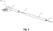
- Figure 1 shows a surgical device 10.
- the device includes a felting needle 1, a distal shaft 2, a buckling wire 3, a proximal shaft 4 and a sliding yoke 5.
- the distal and proximal shafts 2, 4 are hollow and have a tubular shape.
- One section of the felting needle is exposed between the distal shaft 2 and the proximal shaft 4. This section forms the buckling wire 3.
- the sliding yoke 5 is connected to a motor and moves back and forth along the axial direction of the felting needle 1. During this back and forth motion the shafts 2, 4 guide the felting needle 1.
- the shafts 2 and 4 are fixedly attached to the wire forming the felting needle 1 and the buckling wire 3.
- the buckling wire 3 and the felting needle 1 may alternatively each be attached to shafts and be individually formed. In normal operation, the sliding yoke 5 and the at least one felting needle (with the buckling wire 3) move together.
- FIG. 2 shows a sequence of steps that occur, when the at least one felting needle collides with a rigid object.
- a force 11 is exerted on the needle.
- the force 11 is larger than the axial forces during normal operation i.e. during felting an implant to soft tissue.
- This axial force is transferred through a tip of the felting needle 1 to the buckling wire 3.
- the buckling wire 3 reacts by buckling and absorbing the force from the collision.
- the buckling wire relaxes, since the force from the collision reduces.
- the buckling wire 3 can buckle and relax as indicated by arrows 12 and 13 in fig. 2 without breaking.
- the buckling wire 3 effectively decouples the distal shaft and felting needle from the translational actuating motion of the proximal shaft when hitting a hard surface, i.e. a surface with penetration force higher than the buckling force.
- Figure 3A shows a first buckling chamber 6 that can additionally be provided.
- the buckling chamber forms a space around the buckling wire and is formed such that the buckling wire can freely buckle. While figure 3 A shows a spherical chamber, other shapes are also suitable, e.g. a cylindrical or cubicle chamber.
- the chamber is designed such that the buckling wire does not touch a wall when the wire buckles maximally. The maximal extension of the wire can in particular be found experimentally, e.g. by holding the tip of the felting needle in its retracted position.
- Figure 3B shows the relationship between the buckling force (i.e. the force needed to compress the buckling wire) and the axial deformation (i.e. an axial compression of the buckling wire).
- the maximal force is needed to begin buckling.
- the buckling wire does not buckle. Thereby, the felting of an implant to tissue is not hindered by the buckling wire. If the critical force is reached, the wire starts buckling.
- the force needed to buckle the wire further reduces with increased buckling. This reduces the load on the needle tip of the at least one felting needle, which is prevented from breaking inside the patient's body or due to a collision with another surgical instrument.
- Figure 4 A shows a second buckling chamber.
- the second buckling chamber forms a space around the buckling wire and is formed such that the buckling wire is restricted during buckling.
- the second buckling chamber can be formed by a tube 7, in which the felting needle 1, the distal shaft 2, the buckling wire 3, and the proximal shaft 4 are arranged.
- parts of the buckling wire may contact an inner wall of the second buckling chamber. This leads to a thinner device that can be used in difficult to reach soft tissues.
- Figure 4B shows the relationship between the buckling force (i.e. the force needed to compress the buckling wire) and the axial deformation (i.e. an axial compression of the buckling wire) for the restricted buckling shown in figure 4A .
- the restriction i.e. the contact of the buckling wire with an inner wall of the buckling chamber leads to a second peak.
- the critical buckling force of the wire 3 may be the peak that results from the contact.
- the maximal buckling force decreases over time before reaching a plateau.
- a higher buckling force is necessary than the buckling force when the wire buckles for the third or fifth time.
- the reduction in buckling force may be explained by a plastic deformation in the buckling wire.
- the buckling force (approximately) reaches a plateau. This is schematically shown in the graphs of figure 5 .
- the number of deformation cycles is indicated on the x-axis.
- One deformation cycle describes the process of buckling and relaxing the buckling wire once.
- the graph on the left shows the plastic deformation during buckling dependent on the number cycles and the graph on the right shows the buckling force necessary to axially compress the buckling wire dependent on the number of cycles.
- the plastic deformation might be observed as a remaining curvature when the wire is relaxed.
- the buckling force decreases, but reaches a plateau where the buckling force remains constant.
- the number of deformation cycles N indicated in figure 5 until the plateau is reached may be 5, 10, 20, 30 or 40 times.
- pre-bend e.g. buckle
- the buckling wire repeatedly through multiple deformation cycles, the wire prior to use in a patient.
- an operator would receive a surgical device/felting needle with constant properties.
- a device for pre-bending the wire 3 will be explained with reference to figures 6 to 9 .
- Figure 6 shows a perspective view of a device 20 for pre-bending multiple buckling wires 3.
- Figure 7 shows a cross-section of the device of figure 6 and figure 8 shows a schematic view of the device to illustrate a method of pre-bending the buckling wires 3.
- the device 20 includes a body 28 and a handle 24 for actuating the device.
- the handle 24 is connected to a lever 25.
- the lever 25 is connected on one end to the handle 24 and on the other to a drive shaft 26.
- the drive shaft 26 is rotatably connected to the body 28 with a bearing 34.
- the other end of the drive shaft 26 connects to an eccentric 27.
- the device 20 includes a first holding section 21 and a slide 35 with second and third holding sections 22 and 23.
- the second and third holding sections are fixedly connected to each other with a bar.
- the slide 35 can move back and forth along a longitudinal direction on a track 29 in the body 28.
- the third holding section 23 of the slide 35 includes a pin 33.
- the pin 33 is permanently in contact with an outer face of the eccentric 27.
- the first holding section 21 is fixed to the body 28 and the slide 35 and the first holding section 21 are connected to each other with an elastic element (e.g., spring 30) to each other.
- the spring is biased such that the slide 35 is permanently pushed towards the eccentric 27.
- the eccentric 27 When a user actuates the device with the handle 24, the eccentric 27 is rotated. The rotation of the eccentric 27 drives the slide 35 back and forth since the spring 30 pushes the slide 35 permanently against the outer face of the eccentric 27.
- the eccentric 35 has a quadratic shape with rounded edges. However, any other suitable eccentric shape can be used. In the present embodiment, a single rotation of the handle 35 results in the slide sliding 4 times back and forth. Further the body 28 includes a removable back plate 36.
- the device 20 includes a handle 24 the present embodiment, the device could also be driven by a motor as is known in the art.
- the device 20 can receive multiple surgical devices 10 as shown in figure 1 .
- the yoke 5 is removed.
- the felting needles may be protected with a tip cover 31 in order to protect the felting needle and a user of the device 20.
- the back plate 36 is removed. Then, the surgical devices 10 can be inserted from the side of the back plate through the first holding section 21 and the second holding section 22 until the proximal end of the surgical device 10 (proximal end of shaft 4) contacts holding section.
- any one, two or all of the holding sections 21, 22, 23 may comprise additional means to clamp the surgical devices 10.
- the surgical devices 10 can be loosely guided by the holding sections 21, 22, and 23.
- the back plate 36 is closed and the tip cover 31 contacts the back plate at the distal end of the surgical device 10. Now, the surgical device 10 cannot move along its longitudinal direction.
- the third holding section 23 pushes the proximal shaft 4 of the device towards the back plate 36.
- the buckling section 3 starts buckling as can be seen in figure 8 .
- This process is repeated multiple times, e.g. 40 times, until the buckling force as for example depicted in figure 5 reaches a plateau.
- a curve in the buckling wire 3 may remain as can be seen in figure 9 .
Landscapes
- Health & Medical Sciences (AREA)
- Life Sciences & Earth Sciences (AREA)
- Surgery (AREA)
- Molecular Biology (AREA)
- General Health & Medical Sciences (AREA)
- Biomedical Technology (AREA)
- Heart & Thoracic Surgery (AREA)
- Medical Informatics (AREA)
- Nuclear Medicine, Radiotherapy & Molecular Imaging (AREA)
- Animal Behavior & Ethology (AREA)
- Engineering & Computer Science (AREA)
- Public Health (AREA)
- Veterinary Medicine (AREA)
- Oral & Maxillofacial Surgery (AREA)
- Pathology (AREA)
- Surgical Instruments (AREA)
- Prostheses (AREA)
Claims (10)
- Dispositif chirurgical (10) pour feutrer un implant à un tissu mou d'un patient, comprenant au moins une aiguille de feutrage (1) configurée pour se déplacer en va-et-vient, dans lequel le dispositif comprend un mécanisme de protection d'aiguille pour empêcher la au moins une aiguille de feutrage d'être endommagée du fait d'un contact avec une structure rigide pendant le mouvement de va-et-vient, caractérisé en ce que le mécanisme de protection d'aiguille comprend un fil de fléchissement (3) qui transfère le mouvement de va-et-vient d'un actionneur à la au moins une aiguille de feutrage, dans lequel le fil de fléchissement est configuré pour fléchir, si la au moins une aiguille de feutrage entre en contact avec la structure rigide, de telle sorte que le fil de fléchissement est comprimé axialement, dans lequel le fil de fléchissement est dimensionné de telle sorte qu'une force de fléchissement du fil de fléchissement est supérieure à la force de pénétration d'aiguille du tissu mou et inférieure à la force nécessaire pour endommager la au moins une aiguille de feutrage, en particulier plier plastiquement, faire éclater et/ou briser la au moins une aiguille de feutrage, et dans lequel la force de fléchissement est de 0,1 à 40 N, de préférence de 2,5 à 10 N, de manière particulièrement préférable de 4,5 à 7 N.
- Dispositif chirurgical selon l'une quelconque des revendications précédentes, dans lequel le fil de fléchissement comprend ou est fait d'un alliage à mémoire de forme, en particulier le nitinol ou un alliage de nitinol, ou d'un plastique souple élastique et/ou dans lequel le fil a une forme de tube et/ou inclut des découpures.
- Dispositif chirurgical selon l'une quelconque des revendications précédentes, dans lequel le dispositif comprend un ou plusieurs autres fils de fléchissement, qui transfèrent le mouvement de va-et-vient de l'actionneur à la au moins une aiguille de feutrage, dans lequel les un ou plusieurs autres fils de fléchissement sont configurés pour fléchir, si la au moins une aiguille de feutrage entre en contact avec la structure rigide.
- Dispositif chirurgical selon la revendication précédente dans lequel les un ou plusieurs autres fils de fléchissement sont mécaniquement en série ou en parallèle avec le fil de fléchissement et/ou entre eux.
- Dispositif chirurgical selon l'une des revendications précédentes, dans lequel la compression axiale maximale est supérieure à 1 mm, de préférence supérieure à 4 ou 6 mm, de préférence encore 8,5 mm, 12 mm ou plus.
- Dispositif chirurgical selon l'une des revendications précédentes, dans lequel la compression axiale maximale est inférieure à 30, 20 ou 15 mm.
- Dispositif chirurgical selon l'une quelconque des revendications précédentes, dans lequel le fil de fléchissement est pré-plié.
- Dispositif chirurgical selon l'une quelconque des revendications précédentes, dans lequel le dispositif comprend une chambre de fléchissement (6), dans laquelle le fil de fléchissement peut fléchir, dans lequel le fil et la chambre sont configurés de telle sorte que le fil peut fléchir sans limite à l'intérieur de la chambre.
- Dispositif chirurgical selon l'une quelconque des revendications 1 à 7, dans lequel le dispositif comprend une chambre de fléchissement (5), dans laquelle le fil de fléchissement peut fléchir, dans lequel le fil et la chambre sont configurés de telle sorte que le fil entre en contact avec une paroi de la chambre lors du fléchissement de telle sorte que la compression axiale est limitée.
- Dispositif chirurgical selon l'une quelconque des revendications précédentes, dans lequel la au moins une aiguille de feutrage et le fil de fléchissement sont formés d'une pièce, de préférence par un seul fil.
Priority Applications (7)
| Application Number | Priority Date | Filing Date | Title |
|---|---|---|---|
| EP21211467.2A EP4186442B1 (fr) | 2021-11-30 | 2021-11-30 | Dispositif chirurgical avec fil de bouclage |
| JP2024518917A JP2024541179A (ja) | 2021-11-30 | 2022-11-28 | 外科用装置、座屈ワイヤを予備曲げするための装置、軟組織に対して移植物をフェルティングするための方法、および座屈ワイヤを予備曲げするための方法 |
| AU2022399888A AU2022399888A1 (en) | 2021-11-30 | 2022-11-28 | Surgical device, device for pre-bending a buckling wire, method for felting an implant to soft tissue, and method for pre-bending a buckling wire |
| CN202280075540.9A CN118234438A (zh) | 2021-11-30 | 2022-11-28 | 手术设备、预弯曲屈曲线的设备、将植入物毡合到软组织的方法和预弯曲屈曲线的方法 |
| CA3235950A CA3235950A1 (fr) | 2021-11-30 | 2022-11-28 | Dispositif chirurgical, dispositif de pre-cintrage d'un fil de bouclage, procede de feutrage d'un implant sur un tissu mou et procede de pre-cintrage d'un fil de bouclage |
| PCT/EP2022/083491 WO2023099409A1 (fr) | 2021-11-30 | 2022-11-28 | Dispositif chirurgical, dispositif de pré-cintrage d'un fil de bouclage, procédé de feutrage d'un implant sur un tissu mou et procédé de pré-cintrage d'un fil de bouclage |
| US18/694,519 US12544064B2 (en) | 2021-11-30 | 2022-11-28 | Surgical device, device for pre-bending a buckling wire, method for felting an implant to soft tissue, and method for pre-bending a buckling wire |
Applications Claiming Priority (1)
| Application Number | Priority Date | Filing Date | Title |
|---|---|---|---|
| EP21211467.2A EP4186442B1 (fr) | 2021-11-30 | 2021-11-30 | Dispositif chirurgical avec fil de bouclage |
Publications (2)
| Publication Number | Publication Date |
|---|---|
| EP4186442A1 EP4186442A1 (fr) | 2023-05-31 |
| EP4186442B1 true EP4186442B1 (fr) | 2024-08-21 |
Family
ID=78820038
Family Applications (1)
| Application Number | Title | Priority Date | Filing Date |
|---|---|---|---|
| EP21211467.2A Active EP4186442B1 (fr) | 2021-11-30 | 2021-11-30 | Dispositif chirurgical avec fil de bouclage |
Country Status (7)
| Country | Link |
|---|---|
| US (1) | US12544064B2 (fr) |
| EP (1) | EP4186442B1 (fr) |
| JP (1) | JP2024541179A (fr) |
| CN (1) | CN118234438A (fr) |
| AU (1) | AU2022399888A1 (fr) |
| CA (1) | CA3235950A1 (fr) |
| WO (1) | WO2023099409A1 (fr) |
Families Citing this family (2)
| Publication number | Priority date | Publication date | Assignee | Title |
|---|---|---|---|---|
| EP4656159A1 (fr) | 2024-05-31 | 2025-12-03 | ZuriMED Technologies AG | Dispositif de pose, système comprenant le dispositif de pose et procédé de chargement d'un implant en forme de feuille flexible dans un dispositif de pose |
| EP4659705A1 (fr) | 2024-06-05 | 2025-12-10 | ZuriMED Technologies AG | Procédé, ensemble, dispositif de préparation, pince chirurgicale, système et utilisation d'un dispositif de préparation ou pince chirurgicale |
Citations (2)
| Publication number | Priority date | Publication date | Assignee | Title |
|---|---|---|---|---|
| US20190365362A1 (en) * | 2018-06-01 | 2019-12-05 | Spiration, Inc. D/B/A Olympus Respiratory America | Needle device with activation force limiter |
| EP4243702A1 (fr) * | 2020-11-12 | 2023-09-20 | ZuriMED Technologies AG | Dispositif chirurgical, système, et procédé de fabrication d'un dispositif chirurgical |
Family Cites Families (8)
| Publication number | Priority date | Publication date | Assignee | Title |
|---|---|---|---|---|
| JP3336387B2 (ja) * | 2000-06-28 | 2002-10-21 | 広島大学長 | 構造部材の力学挙動観察装置 |
| EP1694214A1 (fr) * | 2003-11-06 | 2006-08-30 | NMT Medical, Inc. | Appareil de ponction transseptale |
| US20080103527A1 (en) * | 2006-10-27 | 2008-05-01 | Martin David T | Flexible endoscopic suture anchor applier |
| US20180168609A1 (en) * | 2016-12-21 | 2018-06-21 | Ethicon Endo-Surgery, Llc | Firing assembly comprising a fuse |
| CN119587097A (zh) * | 2019-05-15 | 2025-03-11 | 苏黎世医疗科技有限公司 | 用于修复或加强人或动物软组织的方法的毡材料 |
| EP4106643B1 (fr) * | 2020-02-21 | 2025-12-17 | Teleflex Life Sciences LLC | Appareil pour empêcher un problème de déploiement de dispositif |
| EP4243922A1 (fr) | 2020-11-12 | 2023-09-20 | ZuriMED Technologies AG | Dispositif médical implantable, procédé de fixation d'une électrode, ensemble et utilisation d'un dispositif médical implantable |
| EP4243698B1 (fr) | 2020-11-12 | 2025-08-20 | ZuriMED Technologies AG | Dispositifs de fixation minimalement invasifs pour fixer un textile feutrable et ensemble comprenant un dispositif de fixation |
-
2021
- 2021-11-30 EP EP21211467.2A patent/EP4186442B1/fr active Active
-
2022
- 2022-11-28 CN CN202280075540.9A patent/CN118234438A/zh active Pending
- 2022-11-28 US US18/694,519 patent/US12544064B2/en active Active
- 2022-11-28 WO PCT/EP2022/083491 patent/WO2023099409A1/fr not_active Ceased
- 2022-11-28 CA CA3235950A patent/CA3235950A1/fr active Pending
- 2022-11-28 JP JP2024518917A patent/JP2024541179A/ja active Pending
- 2022-11-28 AU AU2022399888A patent/AU2022399888A1/en active Pending
Patent Citations (2)
| Publication number | Priority date | Publication date | Assignee | Title |
|---|---|---|---|---|
| US20190365362A1 (en) * | 2018-06-01 | 2019-12-05 | Spiration, Inc. D/B/A Olympus Respiratory America | Needle device with activation force limiter |
| EP4243702A1 (fr) * | 2020-11-12 | 2023-09-20 | ZuriMED Technologies AG | Dispositif chirurgical, système, et procédé de fabrication d'un dispositif chirurgical |
Also Published As
| Publication number | Publication date |
|---|---|
| EP4186442A1 (fr) | 2023-05-31 |
| AU2022399888A1 (en) | 2024-04-04 |
| US12544064B2 (en) | 2026-02-10 |
| CA3235950A1 (fr) | 2023-06-08 |
| JP2024541179A (ja) | 2024-11-08 |
| CN118234438A (zh) | 2024-06-21 |
| US20240389998A1 (en) | 2024-11-28 |
| WO2023099409A1 (fr) | 2023-06-08 |
Similar Documents
| Publication | Publication Date | Title |
|---|---|---|
| AU730285B2 (en) | Non-linear anchor inserter device and bone anchors | |
| JP5558100B2 (ja) | 可撓性内視鏡の縫合糸アンカー適用装置 | |
| EP4186442B1 (fr) | Dispositif chirurgical avec fil de bouclage | |
| US8500629B2 (en) | Endoscopic device | |
| JP4883874B2 (ja) | 脊柱を治療する外科用器具及び方法 | |
| EP0571057A1 (fr) | Manette à aiguilles pour chirurgie endoscopique | |
| US20160051255A1 (en) | Deploying fasteners | |
| US20020077631A1 (en) | Apparatus and methods for tendon or ligament repair | |
| WO2004052594A2 (fr) | Elements articules et procedes d'utilisation | |
| WO1996004853A1 (fr) | Instrument endoscopique de placement de suture | |
| KR20180112108A (ko) | 외과용 클립, 및 이를 위한 클립 조작 디바이스 | |
| JP2006501957A (ja) | ワイヤバスケットを備えた硬性摘出器具 | |
| US11123177B2 (en) | Advanced tendon grasping devices and devices for their application | |
| CA2676038C (fr) | Outil de tunnel pour tissu ouate | |
| EP4424247A1 (fr) | Dispositif chirurgical comprenant une aiguille de feutrage à pointe flexible | |
| JP2025516054A (ja) | ウェッジロック持針器 | |
| JP2003047617A (ja) | 医療用縫合針 | |
| AU2487201A (en) | Non-linear anchor inserter device and bone anchors | |
| HK1201707B (en) | Lancing actuator | |
| HK1123961B (en) | Tissue fasteners and related insertion devices |
Legal Events
| Date | Code | Title | Description |
|---|---|---|---|
| PUAI | Public reference made under article 153(3) epc to a published international application that has entered the european phase |
Free format text: ORIGINAL CODE: 0009012 |
|
| STAA | Information on the status of an ep patent application or granted ep patent |
Free format text: STATUS: THE APPLICATION HAS BEEN PUBLISHED |
|
| AK | Designated contracting states |
Kind code of ref document: A1 Designated state(s): AL AT BE BG CH CY CZ DE DK EE ES FI FR GB GR HR HU IE IS IT LI LT LU LV MC MK MT NL NO PL PT RO RS SE SI SK SM TR |
|
| STAA | Information on the status of an ep patent application or granted ep patent |
Free format text: STATUS: REQUEST FOR EXAMINATION WAS MADE |
|
| 17P | Request for examination filed |
Effective date: 20231127 |
|
| RBV | Designated contracting states (corrected) |
Designated state(s): AL AT BE BG CH CY CZ DE DK EE ES FI FR GB GR HR HU IE IS IT LI LT LU LV MC MK MT NL NO PL PT RO RS SE SI SK SM TR |
|
| GRAJ | Information related to disapproval of communication of intention to grant by the applicant or resumption of examination proceedings by the epo deleted |
Free format text: ORIGINAL CODE: EPIDOSDIGR1 |
|
| STAA | Information on the status of an ep patent application or granted ep patent |
Free format text: STATUS: GRANT OF PATENT IS INTENDED |
|
| GRAP | Despatch of communication of intention to grant a patent |
Free format text: ORIGINAL CODE: EPIDOSNIGR1 |
|
| RIC1 | Information provided on ipc code assigned before grant |
Ipc: A61B 17/06 20060101ALN20240222BHEP Ipc: A61B 17/00 20060101ALN20240222BHEP Ipc: A61B 90/00 20160101ALN20240222BHEP Ipc: A61B 17/062 20060101ALI20240222BHEP Ipc: A61B 17/04 20060101AFI20240222BHEP |
|
| INTG | Intention to grant announced |
Effective date: 20240311 |
|
| GRAS | Grant fee paid |
Free format text: ORIGINAL CODE: EPIDOSNIGR3 |
|
| GRAA | (expected) grant |
Free format text: ORIGINAL CODE: 0009210 |
|
| STAA | Information on the status of an ep patent application or granted ep patent |
Free format text: STATUS: THE PATENT HAS BEEN GRANTED |
|
| P01 | Opt-out of the competence of the unified patent court (upc) registered |
Free format text: CASE NUMBER: APP_39617/2024 Effective date: 20240703 |
|
| AK | Designated contracting states |
Kind code of ref document: B1 Designated state(s): AL AT BE BG CH CY CZ DE DK EE ES FI FR GB GR HR HU IE IS IT LI LT LU LV MC MK MT NL NO PL PT RO RS SE SI SK SM TR |
|
| REG | Reference to a national code |
Ref country code: GB Ref legal event code: FG4D |
|
| REG | Reference to a national code |
Ref country code: CH Ref legal event code: EP |
|
| REG | Reference to a national code |
Ref country code: IE Ref legal event code: FG4D |
|
| REG | Reference to a national code |
Ref country code: DE Ref legal event code: R096 Ref document number: 602021017468 Country of ref document: DE |
|
| REG | Reference to a national code |
Ref country code: LT Ref legal event code: MG9D |
|
| REG | Reference to a national code |
Ref country code: NL Ref legal event code: MP Effective date: 20240821 |
|
| PG25 | Lapsed in a contracting state [announced via postgrant information from national office to epo] |
Ref country code: NO Free format text: LAPSE BECAUSE OF FAILURE TO SUBMIT A TRANSLATION OF THE DESCRIPTION OR TO PAY THE FEE WITHIN THE PRESCRIBED TIME-LIMIT Effective date: 20241121 |
|
| REG | Reference to a national code |
Ref country code: AT Ref legal event code: MK05 Ref document number: 1714710 Country of ref document: AT Kind code of ref document: T Effective date: 20240821 |
|
| PG25 | Lapsed in a contracting state [announced via postgrant information from national office to epo] |
Ref country code: NL Free format text: LAPSE BECAUSE OF FAILURE TO SUBMIT A TRANSLATION OF THE DESCRIPTION OR TO PAY THE FEE WITHIN THE PRESCRIBED TIME-LIMIT Effective date: 20240821 Ref country code: PL Free format text: LAPSE BECAUSE OF FAILURE TO SUBMIT A TRANSLATION OF THE DESCRIPTION OR TO PAY THE FEE WITHIN THE PRESCRIBED TIME-LIMIT Effective date: 20240821 Ref country code: FI Free format text: LAPSE BECAUSE OF FAILURE TO SUBMIT A TRANSLATION OF THE DESCRIPTION OR TO PAY THE FEE WITHIN THE PRESCRIBED TIME-LIMIT Effective date: 20240821 Ref country code: GR Free format text: LAPSE BECAUSE OF FAILURE TO SUBMIT A TRANSLATION OF THE DESCRIPTION OR TO PAY THE FEE WITHIN THE PRESCRIBED TIME-LIMIT Effective date: 20241122 Ref country code: PT Free format text: LAPSE BECAUSE OF FAILURE TO SUBMIT A TRANSLATION OF THE DESCRIPTION OR TO PAY THE FEE WITHIN THE PRESCRIBED TIME-LIMIT Effective date: 20241223 |
|
| PG25 | Lapsed in a contracting state [announced via postgrant information from national office to epo] |
Ref country code: BG Free format text: LAPSE BECAUSE OF FAILURE TO SUBMIT A TRANSLATION OF THE DESCRIPTION OR TO PAY THE FEE WITHIN THE PRESCRIBED TIME-LIMIT Effective date: 20240821 |
|
| PG25 | Lapsed in a contracting state [announced via postgrant information from national office to epo] |
Ref country code: LV Free format text: LAPSE BECAUSE OF FAILURE TO SUBMIT A TRANSLATION OF THE DESCRIPTION OR TO PAY THE FEE WITHIN THE PRESCRIBED TIME-LIMIT Effective date: 20240821 |
|
| PG25 | Lapsed in a contracting state [announced via postgrant information from national office to epo] |
Ref country code: AT Free format text: LAPSE BECAUSE OF FAILURE TO SUBMIT A TRANSLATION OF THE DESCRIPTION OR TO PAY THE FEE WITHIN THE PRESCRIBED TIME-LIMIT Effective date: 20240821 Ref country code: IS Free format text: LAPSE BECAUSE OF FAILURE TO SUBMIT A TRANSLATION OF THE DESCRIPTION OR TO PAY THE FEE WITHIN THE PRESCRIBED TIME-LIMIT Effective date: 20241221 |
|
| PG25 | Lapsed in a contracting state [announced via postgrant information from national office to epo] |
Ref country code: HR Free format text: LAPSE BECAUSE OF FAILURE TO SUBMIT A TRANSLATION OF THE DESCRIPTION OR TO PAY THE FEE WITHIN THE PRESCRIBED TIME-LIMIT Effective date: 20240821 |
|
| PG25 | Lapsed in a contracting state [announced via postgrant information from national office to epo] |
Ref country code: RS Free format text: LAPSE BECAUSE OF FAILURE TO SUBMIT A TRANSLATION OF THE DESCRIPTION OR TO PAY THE FEE WITHIN THE PRESCRIBED TIME-LIMIT Effective date: 20241121 Ref country code: ES Free format text: LAPSE BECAUSE OF FAILURE TO SUBMIT A TRANSLATION OF THE DESCRIPTION OR TO PAY THE FEE WITHIN THE PRESCRIBED TIME-LIMIT Effective date: 20240821 |
|
| PG25 | Lapsed in a contracting state [announced via postgrant information from national office to epo] |
Ref country code: RS Free format text: LAPSE BECAUSE OF FAILURE TO SUBMIT A TRANSLATION OF THE DESCRIPTION OR TO PAY THE FEE WITHIN THE PRESCRIBED TIME-LIMIT Effective date: 20241121 Ref country code: PT Free format text: LAPSE BECAUSE OF FAILURE TO SUBMIT A TRANSLATION OF THE DESCRIPTION OR TO PAY THE FEE WITHIN THE PRESCRIBED TIME-LIMIT Effective date: 20241223 Ref country code: PL Free format text: LAPSE BECAUSE OF FAILURE TO SUBMIT A TRANSLATION OF THE DESCRIPTION OR TO PAY THE FEE WITHIN THE PRESCRIBED TIME-LIMIT Effective date: 20240821 Ref country code: NO Free format text: LAPSE BECAUSE OF FAILURE TO SUBMIT A TRANSLATION OF THE DESCRIPTION OR TO PAY THE FEE WITHIN THE PRESCRIBED TIME-LIMIT Effective date: 20241121 Ref country code: NL Free format text: LAPSE BECAUSE OF FAILURE TO SUBMIT A TRANSLATION OF THE DESCRIPTION OR TO PAY THE FEE WITHIN THE PRESCRIBED TIME-LIMIT Effective date: 20240821 Ref country code: LV Free format text: LAPSE BECAUSE OF FAILURE TO SUBMIT A TRANSLATION OF THE DESCRIPTION OR TO PAY THE FEE WITHIN THE PRESCRIBED TIME-LIMIT Effective date: 20240821 Ref country code: IS Free format text: LAPSE BECAUSE OF FAILURE TO SUBMIT A TRANSLATION OF THE DESCRIPTION OR TO PAY THE FEE WITHIN THE PRESCRIBED TIME-LIMIT Effective date: 20241221 Ref country code: HR Free format text: LAPSE BECAUSE OF FAILURE TO SUBMIT A TRANSLATION OF THE DESCRIPTION OR TO PAY THE FEE WITHIN THE PRESCRIBED TIME-LIMIT Effective date: 20240821 Ref country code: GR Free format text: LAPSE BECAUSE OF FAILURE TO SUBMIT A TRANSLATION OF THE DESCRIPTION OR TO PAY THE FEE WITHIN THE PRESCRIBED TIME-LIMIT Effective date: 20241122 Ref country code: FI Free format text: LAPSE BECAUSE OF FAILURE TO SUBMIT A TRANSLATION OF THE DESCRIPTION OR TO PAY THE FEE WITHIN THE PRESCRIBED TIME-LIMIT Effective date: 20240821 Ref country code: ES Free format text: LAPSE BECAUSE OF FAILURE TO SUBMIT A TRANSLATION OF THE DESCRIPTION OR TO PAY THE FEE WITHIN THE PRESCRIBED TIME-LIMIT Effective date: 20240821 Ref country code: BG Free format text: LAPSE BECAUSE OF FAILURE TO SUBMIT A TRANSLATION OF THE DESCRIPTION OR TO PAY THE FEE WITHIN THE PRESCRIBED TIME-LIMIT Effective date: 20240821 Ref country code: AT Free format text: LAPSE BECAUSE OF FAILURE TO SUBMIT A TRANSLATION OF THE DESCRIPTION OR TO PAY THE FEE WITHIN THE PRESCRIBED TIME-LIMIT Effective date: 20240821 |
|
| PG25 | Lapsed in a contracting state [announced via postgrant information from national office to epo] |
Ref country code: RO Free format text: LAPSE BECAUSE OF FAILURE TO SUBMIT A TRANSLATION OF THE DESCRIPTION OR TO PAY THE FEE WITHIN THE PRESCRIBED TIME-LIMIT Effective date: 20240821 Ref country code: SM Free format text: LAPSE BECAUSE OF FAILURE TO SUBMIT A TRANSLATION OF THE DESCRIPTION OR TO PAY THE FEE WITHIN THE PRESCRIBED TIME-LIMIT Effective date: 20240821 Ref country code: DK Free format text: LAPSE BECAUSE OF FAILURE TO SUBMIT A TRANSLATION OF THE DESCRIPTION OR TO PAY THE FEE WITHIN THE PRESCRIBED TIME-LIMIT Effective date: 20240821 |
|
| PG25 | Lapsed in a contracting state [announced via postgrant information from national office to epo] |
Ref country code: EE Free format text: LAPSE BECAUSE OF FAILURE TO SUBMIT A TRANSLATION OF THE DESCRIPTION OR TO PAY THE FEE WITHIN THE PRESCRIBED TIME-LIMIT Effective date: 20240821 |
|
| PG25 | Lapsed in a contracting state [announced via postgrant information from national office to epo] |
Ref country code: CZ Free format text: LAPSE BECAUSE OF FAILURE TO SUBMIT A TRANSLATION OF THE DESCRIPTION OR TO PAY THE FEE WITHIN THE PRESCRIBED TIME-LIMIT Effective date: 20240821 |
|
| PG25 | Lapsed in a contracting state [announced via postgrant information from national office to epo] |
Ref country code: IT Free format text: LAPSE BECAUSE OF FAILURE TO SUBMIT A TRANSLATION OF THE DESCRIPTION OR TO PAY THE FEE WITHIN THE PRESCRIBED TIME-LIMIT Effective date: 20240821 Ref country code: SK Free format text: LAPSE BECAUSE OF FAILURE TO SUBMIT A TRANSLATION OF THE DESCRIPTION OR TO PAY THE FEE WITHIN THE PRESCRIBED TIME-LIMIT Effective date: 20240821 |
|
| REG | Reference to a national code |
Ref country code: DE Ref legal event code: R097 Ref document number: 602021017468 Country of ref document: DE |
|
| PLBE | No opposition filed within time limit |
Free format text: ORIGINAL CODE: 0009261 |
|
| STAA | Information on the status of an ep patent application or granted ep patent |
Free format text: STATUS: NO OPPOSITION FILED WITHIN TIME LIMIT |
|
| PG25 | Lapsed in a contracting state [announced via postgrant information from national office to epo] |
Ref country code: MC Free format text: LAPSE BECAUSE OF FAILURE TO SUBMIT A TRANSLATION OF THE DESCRIPTION OR TO PAY THE FEE WITHIN THE PRESCRIBED TIME-LIMIT Effective date: 20240821 |
|
| PG25 | Lapsed in a contracting state [announced via postgrant information from national office to epo] |
Ref country code: LU Free format text: LAPSE BECAUSE OF NON-PAYMENT OF DUE FEES Effective date: 20241130 |
|
| 26N | No opposition filed |
Effective date: 20250522 |
|
| REG | Reference to a national code |
Ref country code: BE Ref legal event code: MM Effective date: 20241130 |
|
| PG25 | Lapsed in a contracting state [announced via postgrant information from national office to epo] |
Ref country code: SE Free format text: LAPSE BECAUSE OF FAILURE TO SUBMIT A TRANSLATION OF THE DESCRIPTION OR TO PAY THE FEE WITHIN THE PRESCRIBED TIME-LIMIT Effective date: 20240821 |
|
| PG25 | Lapsed in a contracting state [announced via postgrant information from national office to epo] |
Ref country code: BE Free format text: LAPSE BECAUSE OF NON-PAYMENT OF DUE FEES Effective date: 20241130 |
|
| PG25 | Lapsed in a contracting state [announced via postgrant information from national office to epo] |
Ref country code: IE Free format text: LAPSE BECAUSE OF NON-PAYMENT OF DUE FEES Effective date: 20241130 |
|
| REG | Reference to a national code |
Ref country code: CH Ref legal event code: U11 Free format text: ST27 STATUS EVENT CODE: U-0-0-U10-U11 (AS PROVIDED BY THE NATIONAL OFFICE) Effective date: 20251201 |
|
| PGFP | Annual fee paid to national office [announced via postgrant information from national office to epo] |
Ref country code: DE Payment date: 20251128 Year of fee payment: 5 |
|
| PGFP | Annual fee paid to national office [announced via postgrant information from national office to epo] |
Ref country code: GB Payment date: 20251127 Year of fee payment: 5 |
|
| PGFP | Annual fee paid to national office [announced via postgrant information from national office to epo] |
Ref country code: FR Payment date: 20251124 Year of fee payment: 5 |
|
| PGFP | Annual fee paid to national office [announced via postgrant information from national office to epo] |
Ref country code: CH Payment date: 20251201 Year of fee payment: 5 |
|
| PG25 | Lapsed in a contracting state [announced via postgrant information from national office to epo] |
Ref country code: CY Free format text: LAPSE BECAUSE OF FAILURE TO SUBMIT A TRANSLATION OF THE DESCRIPTION OR TO PAY THE FEE WITHIN THE PRESCRIBED TIME-LIMIT; INVALID AB INITIO Effective date: 20211130 |