EP4186464B1 - Porte-ébauche et ébauche - Google Patents
Porte-ébauche et ébauche Download PDFInfo
- Publication number
- EP4186464B1 EP4186464B1 EP21210619.9A EP21210619A EP4186464B1 EP 4186464 B1 EP4186464 B1 EP 4186464B1 EP 21210619 A EP21210619 A EP 21210619A EP 4186464 B1 EP4186464 B1 EP 4186464B1
- Authority
- EP
- European Patent Office
- Prior art keywords
- blank
- guide shell
- fitting profile
- holder
- blank holder
- Prior art date
- Legal status (The legal status is an assumption and is not a legal conclusion. Google has not performed a legal analysis and makes no representation as to the accuracy of the status listed.)
- Active
Links
Images


Classifications
-
- B—PERFORMING OPERATIONS; TRANSPORTING
- B23—MACHINE TOOLS; METAL-WORKING NOT OTHERWISE PROVIDED FOR
- B23C—MILLING
- B23C9/00—Details or accessories so far as specially adapted to milling machines or cutter
-
- A—HUMAN NECESSITIES
- A61—MEDICAL OR VETERINARY SCIENCE; HYGIENE
- A61C—DENTISTRY; APPARATUS OR METHODS FOR ORAL OR DENTAL HYGIENE
- A61C13/00—Dental prostheses; Making same
- A61C13/0003—Making bridge-work, inlays, implants or the like
- A61C13/0022—Blanks or green, unfinished dental restoration parts
-
- B—PERFORMING OPERATIONS; TRANSPORTING
- B23—MACHINE TOOLS; METAL-WORKING NOT OTHERWISE PROVIDED FOR
- B23C—MILLING
- B23C3/00—Milling particular work; Special milling operations; Machines therefor
- B23C3/16—Working surfaces curved in two directions
-
- B—PERFORMING OPERATIONS; TRANSPORTING
- B23—MACHINE TOOLS; METAL-WORKING NOT OTHERWISE PROVIDED FOR
- B23Q—DETAILS, COMPONENTS, OR ACCESSORIES FOR MACHINE TOOLS, e.g. ARRANGEMENTS FOR COPYING OR CONTROLLING; MACHINE TOOLS IN GENERAL CHARACTERISED BY THE CONSTRUCTION OF PARTICULAR DETAILS OR COMPONENTS; COMBINATIONS OR ASSOCIATIONS OF METAL-WORKING MACHINES, NOT DIRECTED TO A PARTICULAR RESULT
- B23Q3/00—Devices holding, supporting, or positioning work or tools, of a kind normally removable from the machine
- B23Q3/02—Devices holding, supporting, or positioning work or tools, of a kind normally removable from the machine for mounting on a work-table, tool-slide, or analogous part
- B23Q3/06—Work-clamping means
- B23Q3/062—Work-clamping means adapted for holding workpieces having a special form or being made from a special material
-
- B—PERFORMING OPERATIONS; TRANSPORTING
- B23—MACHINE TOOLS; METAL-WORKING NOT OTHERWISE PROVIDED FOR
- B23C—MILLING
- B23C2240/00—Details of connections of tools or workpieces
- B23C2240/21—Glued connections
Definitions
- the invention relates to a blank holder and blank, according to the preamble of claim 1, and to a method for mounting a blank on a blank holder, according to the preamble of claim 14.
- Machining is usually performed in a milling machine.
- a blank holder which in turn has a receiving area for the blank, is permanently attached to the milling machine.
- the material used for the blank is comparatively expensive.
- this peripheral edge not from the blank material, but rather from inexpensive plastic, for example, and to attach the plastic edge to the blank in a suitable manner, for example by gluing. This allows the blank material to be fully utilized.
- the plastic material is generally less compressive than the blank material, especially if the blank is made of ceramic. Therefore, the plastic rim is usually tightly clamped for safe and precise storage.
- the printed matter FR 3 089 782 A1 refers to a customer-specific machined part of one or more dental prosthesis elements.
- the printed matter WO 2011/029615 A1 relates to a dental block for the production of dental prostheses with an attached holder for the machining of the dental block.
- the printed matter DE 10 2018 000727 A1 relates to a dental milling machine with a workpiece holder provided in a work area for a blank to be machined in the work area with a milling tool.
- a frameless blank is gripped in the workpiece holder at its receiving edge and clamped in the workpiece holder for milling.
- the carrier head of the workpiece carrier consists of two clamping jaws that grip the outer circumference of a blank to be machined.
- the clamping jaws grip the outer circumference of the frameless blank over a circumferential angle of up to 180°.
- the blank is secured by clamping the outer edge of the blank between the two movable clamping jaws.
- EP 3 995 106 A1 published on May 11, 2022, claims the priority date of November 6, 2020, is prior art under Art. 54(3) EPC, and relates to a dental milling machine with a workpiece holder provided in a work chamber for a blank to be machined in the work chamber with a milling tool.
- a circular ring-shaped dental blank retaining ring is attached to a dental blank.
- the retaining ring is mounted in the milling holder via a form-fitting profile that runs completely around the outside, such as a dovetail profile. This serves to fasten the retaining ring together with the dental blank in another milling holder.
- EP 4 151 358 A1 published on 22.03.2022 , claims the priority date of 16.09.2021 and is prior art according to Art. 54(3) EPC and relates to a method for holding a blank and a holding device for a blank, with a first holding element for inserting the blank and a second holding element for clamping the blank, which can be locked by a rotary movement on the first holding element.
- WO2020178439A relates to a device for fastening a blank intended for the production of at least one dental reconstruction to a holding device of a processing machine intended for processing the blank.
- the blank has a guide shell on its outer edge.
- the guide shell extends over part of the outer edge of the blank, for example, over a quarter of the outer edge.
- the blank holder with its receiving area has a form-fitting profile. Such a profile typically has an undercut. With such a profile, the blank can be clamped to its guide shell, even if the guide shell is only provided on one side of the blank.
- the blank is supported on one side of the blank holder.
- the blank is not supported all around, but only on one of its sides.
- the support can be provided on one of the side surfaces; for round blanks, it can be provided via an arc or partial circle that extends over less than, preferably significantly less than, 180 degrees.
- the disc axis extends through the center of the disc.
- the spaced points are then spaced apart from each other when viewed parallel to the disc axis.
- the load arm then extends between the points, and the load arm perpendicular to it, corresponding to the distance between the cutter and the connecting line between the points.
- the blank is stored in the receiving area in a very simple manner: The blank is simply screwed or pushed into the form-fitting profile with its guide shell. The relative movement occurs in the longitudinal direction of the profile and thus along the outer edge of the disc-shaped blank.
- the guide shell and form-fitting profile have a matching cross-section. In a storage position, the guide shell fills the receiving area.
- the guide shell extends in an arc along its outer edge, over one-tenth to three-quarters of the outer edge, for example, over one-quarter.
- the form-locking profile also extends in an arc over a pitch circle, which still allows the guide shell to be aligned with the blank so that it is flush with an inlet of the form-locking profile, allowing the guide shell to be screwed into the form-locking profile.
- the sum of the angular extension of the form-locking profile and the guide shell is less than 360 degrees to allow for attachment to the inlet.
- the guide shell of the blank is screwed into the form-locking profile until the storage position is reached.
- the diameter of the round disc-shaped blank can be, for example, 95 mm to 102 mm, with a height between 10 mm and 35 mm.
- Screwing in here refers to a relative rotational movement of the guide shell and the form-fitting profile, which begins with the guide shell being positioned at the entrance of the form-fitting profile and ends when the bearing position is reached.
- the guide shell and the form-fitting profile each extend straight.
- the guide shell is attached to a side surface, i.e., the edge, of the disc-shaped blank. In the case of a rectangular disc, this is preferably a long side and thus not an end face.
- the form-fitting profile extends over essentially the same length as the guide shell, although a considerable length deviation, e.g., of 50%, is also possible.
- the guide shell is aligned flush with an inlet of the form-fitting profile, and the guide shell of the blank is pushed into the form-fitting profile until the storage position is reached.
- the guide shell is preferably made of plastic and attached to the blank, e.g., by gluing. It projects above and below the blank disc.
- the upward and downward projecting areas of the guide shell each form an undercut. These areas are overlapped by the form-fitting profile and ensure stable and secure mounting of the blank disc in the receiving area.
- the guide shell is thus mounted in the form-fitting profile in a form-fitting manner and free of play.
- the profile cross-section of the form-fitting profile is, for example, C-shaped with end legs facing towards one another, which overlap the aforementioned areas or projections of the guide shell.
- the invention also provides a method for mounting a blank on a blank holder.
- This method is characterized in that a guide shell is attached, in particular glued, to the outer circumference of the blank prior to assembly.
- the blank with the guide shell is screwed into a form-fitting profile of a receiving area of the blank holder.
- the first blank can then be reinserted and placed in the locking position. Then, another dental restoration component can be milled at a location different from the tooth.
- an identification code e.g. a QR code
- the blank holder has a machine mount with a bearing plate and a bearing pin protruding from it on its side opposite the blank, it can be suitable for the automatic loading of a workpiece arm of a milling machine.
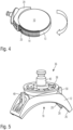
- the Fig. 1 The embodiment shown shows a blank 10 and a blank holder 12, which are fixedly mounted and connected to one another.
- the blank is disc-shaped and in this embodiment circular and has a projecting edge 13.
- the blank has a guide shell 14 on its outer circumference.
- the guide shell 14 is glued to the edge 13 or attached thereto in any other manner.
- a disc axis 16 extends through the disc-shaped blank perpendicular to the main extension direction of the blank.
- the guide shell 14 extends beyond the blank 10. In the illustration according to Fig. 1 the guide shell 14 jumps up and down.
- the projection is a few millimeters, e.g. 1 to 5 mm.
- the guide shell can also be a few millimeters thick and, for example, also 1 mm to 5 mm.
- the blank holder 12 has a receiving area 18 for receiving the blank 10.
- the form-fitting profile 20 is essentially C-shaped. It has end legs 26 and 28. The end legs 26 and 28 overlap the guide shell 14. They extend over projections 30 and 32, at which the guide shell 15 ends when viewed parallel to the disk axis 16. The projections 30 and 32 are thus overlapped by the form-fitting profile 20.
- the dimensions of the guide shell 14 and the form-fitting profile 20 are adapted to each other.
- the form-fitting profile 20 supports the guide shell 14 without play.
- the form-fitting profile 20 has a consistent cross-section throughout its length.
- this cross-section is C-shaped, but it can also have any other suitable shape capable of overlapping the guide shell 14 of the blank 10.
- Fig. 2 the blank 10 is still separated from the blank holder 12. It can be seen that the guide shell with the projections 30 and 32 projects beyond the blank parallel to the disk axis 16 in its extension, in both directions, i.e. in the Fig. 2 viewed upwards and downwards.
- the guide shell 14 is glued to the blank 10. It is made of plastic. Alternatively, the guide shell 14 can be injection-molded, shrunk, or welded onto the blank 10.
- the guide shell 14 extends over an angle of 90° on the outer circumference of the blank.
- This angle of extension can also be significantly smaller, for example, only 20 or 30 degrees. It can be up to 270 degrees if the form-fitting profile 20 extends over 90°.
- Fig. 3 The state of the blank inserted into the form-fitting profile is Fig. 3 visible. In this position, the form-fitting profile 20 is aligned with the guide shell 14.
- the blank with its guide shell can be screwed into the form-fitting profile and thus into the blank holder.
- Fig. 5 The blank holder 12 is visible from behind.
- Two release devices 48 and 50 can be seen. These are firmly connected to the locking lugs 46 and are movable with the blank holder via a bearing tongue 52.
- the bearing tongues 52 press the locking lugs 46 in the direction of the guide shell 14.
- the bearing tongue presses the locking lug 46 into the locking recess 42.
- the locking lugs 46 can be retracted. This disengages them from the locking recesses 42 and 44. In this state, the blank can be rotated and unscrewed from the form-fitting profile 20, allowing the blank to be removed.
- Fig. 7 the blank holder 12 is shown enlarged, showing both locking lugs 46, which fit into the Fig. 6 visible locking recesses 42 and 44.
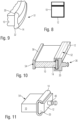
- Both the blank 10 and the blank holder 12 are not curved or circular, but straight.
- the guide shell 14 is just as straight as the form-fitting profile 20. Even with such a shape of the blank 10 with a straight side surface, it is preferably flat—and thus disc-shaped—and has corners and edges.
- the guide shell 14 is glued to a side surface 52 of the blank 10.
- a further guide shell 56 is attached, for example, glued, to an opposite side surface 54. This can be gripped, for example, by a workpiece change arm or inserted directly into a form-fitting profile of another blank holder.
- the guide shell 14 is therefore always attached to the outer circumference of the blank 10.
- FIG. 11 Another embodiment of a combination of blank 10 and blank holder 12, not according to the invention, is shown.
- the guide shell 14 of the blank 10 overlaps the form-fitting profile 20 of the blank holder 12.
- the form-fitting profile 20 and guide shell 14 are designed to match each other, and a play-free bearing arrangement is realized.
- a straight design is provided.
- an arched design is also possible instead, without departing from the scope of the invention.
Landscapes
- Health & Medical Sciences (AREA)
- Engineering & Computer Science (AREA)
- Mechanical Engineering (AREA)
- General Health & Medical Sciences (AREA)
- Dentistry (AREA)
- Epidemiology (AREA)
- Life Sciences & Earth Sciences (AREA)
- Animal Behavior & Ethology (AREA)
- Oral & Maxillofacial Surgery (AREA)
- Public Health (AREA)
- Veterinary Medicine (AREA)
- Jigs For Machine Tools (AREA)
- Connection Of Plates (AREA)
- Feeding And Guiding Record Carriers (AREA)
- Packaging For Recording Disks (AREA)
- Dental Tools And Instruments Or Auxiliary Dental Instruments (AREA)
Claims (14)
- Porte-lingotin (12) et lingotin en forme de disque (10), le porte-lingotin (12) ayant une zone de réception (18) pour le lingotin en forme de disque, où la zone de réception est incurvée et le lingotin présente une coquille de guidage en forme de cercle partiel (14), caractérisée en ce que la zone de réception forme un profilé à liaison de forme en forme de cercle partiel ou en forme d'arc (20), et la coquille de guidage partiellement circulaire peut être vissée dans le profilé à liaison de forme.
- Porte-lingotin et lingotin selon la revendication 1, caractérisés en ce que le profilé à liaison de forme supporte sans jeu la coquille de guidage.
- Porte-lingotin et lingotin selon l'une des revendications précédentes, caractérisés en ce que le profilé à liaison de forme est monobloc et/ou s'étend jusqu'à la coquille de guidage.
- Porte-lingotin et lingotin selon l'une des revendications précédentes, caractérisés en ce que le profilé à liaison de forme est de section transversale en forme de C et comporte des branches d'extrémité (26, 28) tournées l'une vers l'autre, qui s'engagent derrière et/ou par-dessus la coquille de guidage ou une partie de la coquille de guidage.
- Porte-lingotin et lingotin selon l'une des revendications précédentes, caractérisés en ce que la coquille de guidage est reliée au lingotin et s'étend en forme de cercle ou de cercle partiel le long de la circonférence du lingotin.
- Porte-lingotin et lingotin selon l'une des revendications précédentes, caractérisés en ce que le profilé à liaison de forme et la coquille de guidage s'enclenchent l'un sur l'autre lors du vissage ou de l'insertion.
- Porte-lingotin et lingotin selon la revendication 6, caractérisés en ce que profilé à liaison de forme comporte au moins un ergot d'encliquetage (46) orienté vers la coquille de guidage, qui interagit avec au moins un évidement d'encliquetage (42) de la coquille de guidage, et en particulier en ce que l'ergot ou les ergots d'encliquetage sont précontraintes radialement vers l'intérieur, ou en ce que la coquille de guidage comporte au moins un ergot d'encliquetage orienté vers le profilé à liaison de forme qui interagit avec au moins un évidement d'encliquetage du profilé à liaison de forme et en particulier en ce qu'au moins un ergot d'encliquetage est précontrainte vers le profilé à liaison de forme.
- Porte-lingotin et lingotin selon la revendication 7, caractérisés en ce que 2 ergots d'encliquetage espacées dans le sens circonférentiel agissent dans des sens de rotation opposés par rapport au lingotin.
- Porte-lingotin et lingotin selon l'une des revendications précédentes, caractérisés en ce que le lingotin avec la coquille de guidage peut être détachée du profilé à liaison de forme par rotation dans le sens longitudinal du profil à liaison de forme, en surmontant éventuellement une force de verrouillage.
- Porte-lingotin et lingotin selon les revendications 6 à 9, caractérisés en ce que le profilé à liaison de forme comporte un dispositif de déverrouillage au moyen duquel ledit au moins un ergot de verrouillage peut être amené hors de prise dudit au moins un évidemment d'encliquetage.
- Porte-lingotin et lingotin selon l'une des revendications précédentes, caractérisés en ce que la coquille de guidage et/ou le profilé à liaison de forme présente au moins un chanfrein d'insertion sur des surfaces orientées l'une vers l'autre.
- Porte-lingotin et lingotin selon l'une des revendications précédentes, caractérisés en ce que la coquille de guidage s'étend sur plus de 15 % de la circonférence du lingotin et moins de 100 % de la circonférence du lingotin, en particulier sur moins de 50% de la circonférence et de manière particulièrement préférée sur 20 % à 30 %.
- Porte-lingotin et lingotin selon l'une des revendications précédentes, caractérisés en ce que le porte-lingotin comporte sur son côté opposé au lingotin, un logement de machine (36) avec une plaque d'appui (38) et un tourillon (40) dépassant de celui-ci, lequel logement de machine est conçu pour le chargement automatique d'un bras porte-pièce d'une fraiseuse.
- Procédé de montage d'un lingotin (10) sur un porte-lingotin (12), où une coquille de guidage en forme de cercle partiel (14) est reliée, en particulier collée, sur la périphérie extérieure du lingotin avant l'assemblage caractérisée en ce que le lingotin avec la coquille de guidage en forme de cercle partiel est vissée dans un profil à liaison de forme en forme de cercle partiel ou en forme d'arc (20) d'une zone de réception (18) du porte-lingotin jusqu'à ce que le lingotin soit enclenché et reliée à la coquille de guidage sur une butée en position d'encliquetage.
Priority Applications (5)
| Application Number | Priority Date | Filing Date | Title |
|---|---|---|---|
| ES21210619T ES3037491T3 (en) | 2021-11-25 | 2021-11-25 | Blank holder and blank |
| EP21210619.9A EP4186464B1 (fr) | 2021-11-25 | 2021-11-25 | Porte-ébauche et ébauche |
| EP25187734.6A EP4603223A3 (fr) | 2021-11-25 | 2021-11-25 | Support d'ébauche et ébauche |
| US18/056,306 US11938552B2 (en) | 2021-11-25 | 2022-11-17 | Blank holder and blank |
| US18/582,857 US12296396B2 (en) | 2021-11-25 | 2024-02-21 | Blank holder and blank |
Applications Claiming Priority (1)
| Application Number | Priority Date | Filing Date | Title |
|---|---|---|---|
| EP21210619.9A EP4186464B1 (fr) | 2021-11-25 | 2021-11-25 | Porte-ébauche et ébauche |
Related Child Applications (1)
| Application Number | Title | Priority Date | Filing Date |
|---|---|---|---|
| EP25187734.6A Division EP4603223A3 (fr) | 2021-11-25 | 2021-11-25 | Support d'ébauche et ébauche |
Publications (2)
| Publication Number | Publication Date |
|---|---|
| EP4186464A1 EP4186464A1 (fr) | 2023-05-31 |
| EP4186464B1 true EP4186464B1 (fr) | 2025-07-09 |
Family
ID=78806272
Family Applications (2)
| Application Number | Title | Priority Date | Filing Date |
|---|---|---|---|
| EP25187734.6A Pending EP4603223A3 (fr) | 2021-11-25 | 2021-11-25 | Support d'ébauche et ébauche |
| EP21210619.9A Active EP4186464B1 (fr) | 2021-11-25 | 2021-11-25 | Porte-ébauche et ébauche |
Family Applications Before (1)
| Application Number | Title | Priority Date | Filing Date |
|---|---|---|---|
| EP25187734.6A Pending EP4603223A3 (fr) | 2021-11-25 | 2021-11-25 | Support d'ébauche et ébauche |
Country Status (3)
| Country | Link |
|---|---|
| US (2) | US11938552B2 (fr) |
| EP (2) | EP4603223A3 (fr) |
| ES (1) | ES3037491T3 (fr) |
Families Citing this family (2)
| Publication number | Priority date | Publication date | Assignee | Title |
|---|---|---|---|---|
| ES3037491T3 (en) * | 2021-11-25 | 2025-10-02 | Ivoclar Vivadent Ag | Blank holder and blank |
| CN116849850A (zh) * | 2023-07-10 | 2023-10-10 | 爱迪特(秦皇岛)科技股份有限公司 | 一种全口义齿牙科假体及其制备方法和应用 |
Citations (5)
| Publication number | Priority date | Publication date | Assignee | Title |
|---|---|---|---|---|
| DE102018000727A1 (de) * | 2017-02-03 | 2018-08-09 | vhf camfacture Aktiengesellschaft | Dentalfräsmaschine |
| WO2020178439A1 (fr) * | 2019-03-07 | 2020-09-10 | ORGANICAL CAD/CAM GmbH | Dispositif de fixation d'une ébauche dentaire à une machine d'usinage |
| WO2021048299A1 (fr) * | 2019-09-12 | 2021-03-18 | Heinrich Steger | Dispositif de retenue d'une pièce dentaire |
| EP3995106A1 (fr) * | 2020-11-06 | 2022-05-11 | Ivoclar Vivadent AG | Anneau de support de flan circulaire dentaire |
| EP4151358A1 (fr) * | 2021-09-16 | 2023-03-22 | Ivoclar Vivadent AG | Dispositif de maintien pour une ébauche |
Family Cites Families (9)
| Publication number | Priority date | Publication date | Assignee | Title |
|---|---|---|---|---|
| DE3131016A1 (de) * | 1981-08-05 | 1983-02-24 | Carl Hurth Maschinen- und Zahnradfabrik GmbH & Co, 8000 München | Verfahren zum selbstaendigen werkstueckwechsel an einer werkzeugmaschine und dafuer geeignete vorrichtung |
| DE19714223A1 (de) * | 1997-04-07 | 1998-10-08 | Megadenta Gmbh Dentalprodukte | Vorrichtung zur Befestigung eines Formkörpers an einer Bearbeitungsmaschine, insbesondere zur Herstellung einer Zahnrestauration |
| BR0115981B1 (pt) | 2000-12-07 | 2010-06-01 | dispositivo de retenção para peças brutas de cerámica. | |
| DE112004000561B4 (de) | 2003-04-04 | 2010-01-07 | Xawex Ag | Verfahren zur Herstellung von zahnmedizinischen Rekonstruktionen |
| DE102009011672A1 (de) * | 2009-01-16 | 2010-07-22 | Wieland Dental + Technik Gmbh & Co. Kg | Bearbeitungsmaschine |
| DE202009018693U1 (de) * | 2009-09-11 | 2012-10-19 | Pritidenta B. V. | Zahnblock zur Fertigung von Zahnersatzteilen mit daran befestigtem Halter |
| US9675433B2 (en) * | 2012-11-29 | 2017-06-13 | Jensen Industries Inc. | Adapter for dental milling blank |
| FR3089782B1 (fr) * | 2018-12-13 | 2022-07-29 | Lyra France | Adaptateur réutilisable pour bloc d'usinage d'au moins un élément prothétique dentaire |
| ES3037491T3 (en) * | 2021-11-25 | 2025-10-02 | Ivoclar Vivadent Ag | Blank holder and blank |
-
2021
- 2021-11-25 ES ES21210619T patent/ES3037491T3/es active Active
- 2021-11-25 EP EP25187734.6A patent/EP4603223A3/fr active Pending
- 2021-11-25 EP EP21210619.9A patent/EP4186464B1/fr active Active
-
2022
- 2022-11-17 US US18/056,306 patent/US11938552B2/en active Active
-
2024
- 2024-02-21 US US18/582,857 patent/US12296396B2/en active Active
Patent Citations (5)
| Publication number | Priority date | Publication date | Assignee | Title |
|---|---|---|---|---|
| DE102018000727A1 (de) * | 2017-02-03 | 2018-08-09 | vhf camfacture Aktiengesellschaft | Dentalfräsmaschine |
| WO2020178439A1 (fr) * | 2019-03-07 | 2020-09-10 | ORGANICAL CAD/CAM GmbH | Dispositif de fixation d'une ébauche dentaire à une machine d'usinage |
| WO2021048299A1 (fr) * | 2019-09-12 | 2021-03-18 | Heinrich Steger | Dispositif de retenue d'une pièce dentaire |
| EP3995106A1 (fr) * | 2020-11-06 | 2022-05-11 | Ivoclar Vivadent AG | Anneau de support de flan circulaire dentaire |
| EP4151358A1 (fr) * | 2021-09-16 | 2023-03-22 | Ivoclar Vivadent AG | Dispositif de maintien pour une ébauche |
Also Published As
| Publication number | Publication date |
|---|---|
| EP4603223A2 (fr) | 2025-08-20 |
| EP4186464A1 (fr) | 2023-05-31 |
| US20230158584A1 (en) | 2023-05-25 |
| US12296396B2 (en) | 2025-05-13 |
| EP4603223A3 (fr) | 2025-10-29 |
| ES3037491T3 (en) | 2025-10-02 |
| US20240189929A1 (en) | 2024-06-13 |
| US11938552B2 (en) | 2024-03-26 |
Similar Documents
| Publication | Publication Date | Title |
|---|---|---|
| WO2013117540A1 (fr) | Logement d'ébauche pour machine de fraisage dentaire | |
| EP3047818B1 (fr) | Dispositif de retenue pour une piece dentaire | |
| EP2456584B1 (fr) | Dispositif d'alignement | |
| DE102012102059B4 (de) | Haltevorrichtung für Abutment-Rohlinge, Set aus Haltevorrichtung und zu bearbeitendem Aufbau, Aufbau-Rohling und Zahnimplantat-Analog | |
| EP2625003B1 (fr) | Fermeture rapide mécanique linéaire | |
| DE202013103515U1 (de) | Rohlingaufnahme sowie Dental-Fräsmaschine | |
| EP0182290A2 (fr) | Tête de fraisage | |
| DE3317916A1 (de) | Fraeswerkzeug | |
| EP1068839A2 (fr) | Préforme pour l'usinage de prothèses dentaires | |
| EP3209240B1 (fr) | Fraiseuse et ébauche d'un composant de dentisterie | |
| EP1147841B1 (fr) | Plaquette de coupe et outil pour fraiser | |
| AT522915B1 (de) | Haltevorrichtung für ein dentales Werkstück | |
| EP1140400A1 (fr) | Outil a enlevement de copeaux pour usinage a vitesse elevee | |
| EP4603223A2 (fr) | Support d'ébauche et ébauche | |
| DE202015100491U1 (de) | Werkstückhalter | |
| EP3995106B1 (fr) | Anneau de support de flan circulaire dentaire | |
| DE2533495B2 (de) | Bohrstange | |
| DE20315143U1 (de) | Justierring für Stanzstempel | |
| EP0263476A2 (fr) | Procédé d'alignement d'une palette sur une table d'une machine-outil et pièce d'alignement à cet effet | |
| EP0873815A2 (fr) | Serrage d'une pièce par boulon de serrage | |
| EP1715975B1 (fr) | Fraise a vitesse elevee | |
| EP1948396A1 (fr) | Cavite pour outil de meulage, outil de meulage et corps support pour outil de meulage | |
| EP4374817B1 (fr) | Pièce de traitement dentaire | |
| EP3412246B1 (fr) | Support pour ébauche de pilier pour implants dentaires | |
| DE19635903C2 (de) | Messer für einen Messerkopf |
Legal Events
| Date | Code | Title | Description |
|---|---|---|---|
| PUAI | Public reference made under article 153(3) epc to a published international application that has entered the european phase |
Free format text: ORIGINAL CODE: 0009012 |
|
| STAA | Information on the status of an ep patent application or granted ep patent |
Free format text: STATUS: THE APPLICATION HAS BEEN PUBLISHED |
|
| AK | Designated contracting states |
Kind code of ref document: A1 Designated state(s): AL AT BE BG CH CY CZ DE DK EE ES FI FR GB GR HR HU IE IS IT LI LT LU LV MC MK MT NL NO PL PT RO RS SE SI SK SM TR |
|
| STAA | Information on the status of an ep patent application or granted ep patent |
Free format text: STATUS: REQUEST FOR EXAMINATION WAS MADE |
|
| 17P | Request for examination filed |
Effective date: 20231106 |
|
| RBV | Designated contracting states (corrected) |
Designated state(s): AL AT BE BG CH CY CZ DE DK EE ES FI FR GB GR HR HU IE IS IT LI LT LU LV MC MK MT NL NO PL PT RO RS SE SI SK SM TR |
|
| STAA | Information on the status of an ep patent application or granted ep patent |
Free format text: STATUS: EXAMINATION IS IN PROGRESS |
|
| 17Q | First examination report despatched |
Effective date: 20240228 |
|
| GRAP | Despatch of communication of intention to grant a patent |
Free format text: ORIGINAL CODE: EPIDOSNIGR1 |
|
| STAA | Information on the status of an ep patent application or granted ep patent |
Free format text: STATUS: GRANT OF PATENT IS INTENDED |
|
| INTG | Intention to grant announced |
Effective date: 20250204 |
|
| GRAS | Grant fee paid |
Free format text: ORIGINAL CODE: EPIDOSNIGR3 |
|
| GRAA | (expected) grant |
Free format text: ORIGINAL CODE: 0009210 |
|
| STAA | Information on the status of an ep patent application or granted ep patent |
Free format text: STATUS: THE PATENT HAS BEEN GRANTED |
|
| P01 | Opt-out of the competence of the unified patent court (upc) registered |
Free format text: CASE NUMBER: APP_22075/2025 Effective date: 20250509 |
|
| AK | Designated contracting states |
Kind code of ref document: B1 Designated state(s): AL AT BE BG CH CY CZ DE DK EE ES FI FR GB GR HR HU IE IS IT LI LT LU LV MC MK MT NL NO PL PT RO RS SE SI SK SM TR |
|
| REG | Reference to a national code |
Ref country code: GB Ref legal event code: FG4D Free format text: NOT ENGLISH |
|
| REG | Reference to a national code |
Ref country code: CH Ref legal event code: EP |
|
| REG | Reference to a national code |
Ref country code: IE Ref legal event code: FG4D Free format text: LANGUAGE OF EP DOCUMENT: GERMAN |
|
| REG | Reference to a national code |
Ref country code: DE Ref legal event code: R096 Ref document number: 502021007958 Country of ref document: DE |
|
| REG | Reference to a national code |
Ref country code: NL Ref legal event code: FP |
|
| REG | Reference to a national code |
Ref country code: ES Ref legal event code: FG2A Ref document number: 3037491 Country of ref document: ES Kind code of ref document: T3 Effective date: 20251002 |
|
| PG25 | Lapsed in a contracting state [announced via postgrant information from national office to epo] |
Ref country code: PT Free format text: LAPSE BECAUSE OF FAILURE TO SUBMIT A TRANSLATION OF THE DESCRIPTION OR TO PAY THE FEE WITHIN THE PRESCRIBED TIME-LIMIT Effective date: 20251110 |
|
| PGFP | Annual fee paid to national office [announced via postgrant information from national office to epo] |
Ref country code: NL Payment date: 20251118 Year of fee payment: 5 |
|
| REG | Reference to a national code |
Ref country code: CH Ref legal event code: U11 Free format text: ST27 STATUS EVENT CODE: U-0-0-U10-U11 (AS PROVIDED BY THE NATIONAL OFFICE) Effective date: 20251218 |
|
| PG25 | Lapsed in a contracting state [announced via postgrant information from national office to epo] |
Ref country code: IS Free format text: LAPSE BECAUSE OF FAILURE TO SUBMIT A TRANSLATION OF THE DESCRIPTION OR TO PAY THE FEE WITHIN THE PRESCRIBED TIME-LIMIT Effective date: 20251109 |
|
| PGFP | Annual fee paid to national office [announced via postgrant information from national office to epo] |
Ref country code: DE Payment date: 20251118 Year of fee payment: 5 |
|
| PGFP | Annual fee paid to national office [announced via postgrant information from national office to epo] |
Ref country code: GB Payment date: 20251125 Year of fee payment: 5 |
|
| PG25 | Lapsed in a contracting state [announced via postgrant information from national office to epo] |
Ref country code: NO Free format text: LAPSE BECAUSE OF FAILURE TO SUBMIT A TRANSLATION OF THE DESCRIPTION OR TO PAY THE FEE WITHIN THE PRESCRIBED TIME-LIMIT Effective date: 20251009 |
|
| REG | Reference to a national code |
Ref country code: LT Ref legal event code: MG9D |
|
| PGFP | Annual fee paid to national office [announced via postgrant information from national office to epo] |
Ref country code: AT Payment date: 20260113 Year of fee payment: 5 |
|
| PG25 | Lapsed in a contracting state [announced via postgrant information from national office to epo] |
Ref country code: FI Free format text: LAPSE BECAUSE OF FAILURE TO SUBMIT A TRANSLATION OF THE DESCRIPTION OR TO PAY THE FEE WITHIN THE PRESCRIBED TIME-LIMIT Effective date: 20250709 |
|
| PGFP | Annual fee paid to national office [announced via postgrant information from national office to epo] |
Ref country code: IT Payment date: 20251119 Year of fee payment: 5 |
|
| PG25 | Lapsed in a contracting state [announced via postgrant information from national office to epo] |
Ref country code: HR Free format text: LAPSE BECAUSE OF FAILURE TO SUBMIT A TRANSLATION OF THE DESCRIPTION OR TO PAY THE FEE WITHIN THE PRESCRIBED TIME-LIMIT Effective date: 20250709 |
|
| PGFP | Annual fee paid to national office [announced via postgrant information from national office to epo] |
Ref country code: FR Payment date: 20251126 Year of fee payment: 5 |
|
| PG25 | Lapsed in a contracting state [announced via postgrant information from national office to epo] |
Ref country code: GR Free format text: LAPSE BECAUSE OF FAILURE TO SUBMIT A TRANSLATION OF THE DESCRIPTION OR TO PAY THE FEE WITHIN THE PRESCRIBED TIME-LIMIT Effective date: 20251010 |
|
| PGFP | Annual fee paid to national office [announced via postgrant information from national office to epo] |
Ref country code: CH Payment date: 20251218 Year of fee payment: 5 |
|
| PG25 | Lapsed in a contracting state [announced via postgrant information from national office to epo] |
Ref country code: SE Free format text: LAPSE BECAUSE OF FAILURE TO SUBMIT A TRANSLATION OF THE DESCRIPTION OR TO PAY THE FEE WITHIN THE PRESCRIBED TIME-LIMIT Effective date: 20250709 |
|
| PG25 | Lapsed in a contracting state [announced via postgrant information from national office to epo] |
Ref country code: LV Free format text: LAPSE BECAUSE OF FAILURE TO SUBMIT A TRANSLATION OF THE DESCRIPTION OR TO PAY THE FEE WITHIN THE PRESCRIBED TIME-LIMIT Effective date: 20250709 |
|
| PG25 | Lapsed in a contracting state [announced via postgrant information from national office to epo] |
Ref country code: BG Free format text: LAPSE BECAUSE OF FAILURE TO SUBMIT A TRANSLATION OF THE DESCRIPTION OR TO PAY THE FEE WITHIN THE PRESCRIBED TIME-LIMIT Effective date: 20250709 Ref country code: PL Free format text: LAPSE BECAUSE OF FAILURE TO SUBMIT A TRANSLATION OF THE DESCRIPTION OR TO PAY THE FEE WITHIN THE PRESCRIBED TIME-LIMIT Effective date: 20250709 |
|
| PG25 | Lapsed in a contracting state [announced via postgrant information from national office to epo] |
Ref country code: RS Free format text: LAPSE BECAUSE OF FAILURE TO SUBMIT A TRANSLATION OF THE DESCRIPTION OR TO PAY THE FEE WITHIN THE PRESCRIBED TIME-LIMIT Effective date: 20251009 |
|
| PGFP | Annual fee paid to national office [announced via postgrant information from national office to epo] |
Ref country code: ES Payment date: 20251208 Year of fee payment: 5 |
|
| PG25 | Lapsed in a contracting state [announced via postgrant information from national office to epo] |
Ref country code: RO Free format text: LAPSE BECAUSE OF FAILURE TO SUBMIT A TRANSLATION OF THE DESCRIPTION OR TO PAY THE FEE WITHIN THE PRESCRIBED TIME-LIMIT Effective date: 20250709 |
|
| PG25 | Lapsed in a contracting state [announced via postgrant information from national office to epo] |
Ref country code: SM Free format text: LAPSE BECAUSE OF FAILURE TO SUBMIT A TRANSLATION OF THE DESCRIPTION OR TO PAY THE FEE WITHIN THE PRESCRIBED TIME-LIMIT Effective date: 20250709 |
|
| PG25 | Lapsed in a contracting state [announced via postgrant information from national office to epo] |
Ref country code: DK Free format text: LAPSE BECAUSE OF FAILURE TO SUBMIT A TRANSLATION OF THE DESCRIPTION OR TO PAY THE FEE WITHIN THE PRESCRIBED TIME-LIMIT Effective date: 20250709 |
|
| PG25 | Lapsed in a contracting state [announced via postgrant information from national office to epo] |
Ref country code: CZ Free format text: LAPSE BECAUSE OF FAILURE TO SUBMIT A TRANSLATION OF THE DESCRIPTION OR TO PAY THE FEE WITHIN THE PRESCRIBED TIME-LIMIT Effective date: 20250709 |
|
| PG25 | Lapsed in a contracting state [announced via postgrant information from national office to epo] |
Ref country code: EE Free format text: LAPSE BECAUSE OF FAILURE TO SUBMIT A TRANSLATION OF THE DESCRIPTION OR TO PAY THE FEE WITHIN THE PRESCRIBED TIME-LIMIT Effective date: 20250709 Ref country code: SK Free format text: LAPSE BECAUSE OF FAILURE TO SUBMIT A TRANSLATION OF THE DESCRIPTION OR TO PAY THE FEE WITHIN THE PRESCRIBED TIME-LIMIT Effective date: 20250709 |
|
| PLBE | No opposition filed within time limit |
Free format text: ORIGINAL CODE: 0009261 |
|
| STAA | Information on the status of an ep patent application or granted ep patent |
Free format text: STATUS: NO OPPOSITION FILED WITHIN TIME LIMIT |