EP4186582A1 - Mit dem zyklon integrierte tremisstaubsammeleinheit - Google Patents
Mit dem zyklon integrierte tremisstaubsammeleinheit Download PDFInfo
- Publication number
- EP4186582A1 EP4186582A1 EP22197627.7A EP22197627A EP4186582A1 EP 4186582 A1 EP4186582 A1 EP 4186582A1 EP 22197627 A EP22197627 A EP 22197627A EP 4186582 A1 EP4186582 A1 EP 4186582A1
- Authority
- EP
- European Patent Office
- Prior art keywords
- unit
- tremie
- filter
- dust
- air
- Prior art date
- Legal status (The legal status is an assumption and is not a legal conclusion. Google has not performed a legal analysis and makes no representation as to the accuracy of the status listed.)
- Withdrawn
Links
- 239000000428 dust Substances 0.000 title claims abstract description 55
- 239000004744 fabric Substances 0.000 claims abstract description 32
- 238000004140 cleaning Methods 0.000 claims abstract description 23
- 239000002245 particle Substances 0.000 claims abstract description 7
- 230000008878 coupling Effects 0.000 claims description 13
- 238000010168 coupling process Methods 0.000 claims description 13
- 238000005859 coupling reaction Methods 0.000 claims description 13
- 238000007789 sealing Methods 0.000 claims description 7
- 238000012546 transfer Methods 0.000 claims description 5
- 235000013339 cereals Nutrition 0.000 description 20
- 239000000126 substance Substances 0.000 description 8
- 238000000034 method Methods 0.000 description 6
- 238000012423 maintenance Methods 0.000 description 5
- 230000008569 process Effects 0.000 description 5
- 230000008439 repair process Effects 0.000 description 4
- 241000209140 Triticum Species 0.000 description 3
- 235000021307 Triticum Nutrition 0.000 description 3
- 230000000737 periodic effect Effects 0.000 description 3
- 239000000047 product Substances 0.000 description 3
- 241000196324 Embryophyta Species 0.000 description 2
- XEEYBQQBJWHFJM-UHFFFAOYSA-N Iron Chemical compound [Fe] XEEYBQQBJWHFJM-UHFFFAOYSA-N 0.000 description 2
- 239000012467 final product Substances 0.000 description 2
- 239000010903 husk Substances 0.000 description 2
- 238000004519 manufacturing process Methods 0.000 description 2
- 238000003860 storage Methods 0.000 description 2
- 241000273930 Brevoortia tyrannus Species 0.000 description 1
- 241000238631 Hexapoda Species 0.000 description 1
- 229910000831 Steel Inorganic materials 0.000 description 1
- 230000002411 adverse Effects 0.000 description 1
- 238000000137 annealing Methods 0.000 description 1
- 238000013459 approach Methods 0.000 description 1
- 238000010276 construction Methods 0.000 description 1
- 230000003247 decreasing effect Effects 0.000 description 1
- 238000013461 design Methods 0.000 description 1
- 230000000694 effects Effects 0.000 description 1
- 238000011156 evaluation Methods 0.000 description 1
- 230000001747 exhibiting effect Effects 0.000 description 1
- 239000012634 fragment Substances 0.000 description 1
- 238000003306 harvesting Methods 0.000 description 1
- 230000006872 improvement Effects 0.000 description 1
- 238000009434 installation Methods 0.000 description 1
- 229910052742 iron Inorganic materials 0.000 description 1
- 230000000670 limiting effect Effects 0.000 description 1
- 239000002184 metal Substances 0.000 description 1
- 229910052751 metal Inorganic materials 0.000 description 1
- 244000005700 microbiome Species 0.000 description 1
- JTJMJGYZQZDUJJ-UHFFFAOYSA-N phencyclidine Chemical class C1CCCCN1C1(C=2C=CC=CC=2)CCCCC1 JTJMJGYZQZDUJJ-UHFFFAOYSA-N 0.000 description 1
- 231100000614 poison Toxicity 0.000 description 1
- 238000000926 separation method Methods 0.000 description 1
- 239000002689 soil Substances 0.000 description 1
- 238000003892 spreading Methods 0.000 description 1
- 230000007480 spreading Effects 0.000 description 1
- 239000010904 stalk Substances 0.000 description 1
- 239000010959 steel Substances 0.000 description 1
- 239000004575 stone Substances 0.000 description 1
- 239000010902 straw Substances 0.000 description 1
- 230000001360 synchronised effect Effects 0.000 description 1
- 239000003440 toxic substance Substances 0.000 description 1
- 239000002699 waste material Substances 0.000 description 1
- 238000005303 weighing Methods 0.000 description 1
Images






Classifications
-
- B—PERFORMING OPERATIONS; TRANSPORTING
- B65—CONVEYING; PACKING; STORING; HANDLING THIN OR FILAMENTARY MATERIAL
- B65G—TRANSPORT OR STORAGE DEVICES, e.g. CONVEYORS FOR LOADING OR TIPPING, SHOP CONVEYOR SYSTEMS OR PNEUMATIC TUBE CONVEYORS
- B65G69/00—Auxiliary measures taken, or devices used, in connection with loading or unloading
- B65G69/18—Preventing escape of dust
-
- B—PERFORMING OPERATIONS; TRANSPORTING
- B01—PHYSICAL OR CHEMICAL PROCESSES OR APPARATUS IN GENERAL
- B01D—SEPARATION
- B01D46/00—Filters or filtering processes specially modified for separating dispersed particles from gases or vapours
- B01D46/66—Regeneration of the filtering material or filter elements inside the filter
- B01D46/68—Regeneration of the filtering material or filter elements inside the filter by means acting on the cake side involving movement with regard to the filter elements
- B01D46/681—Regeneration of the filtering material or filter elements inside the filter by means acting on the cake side involving movement with regard to the filter elements by scrapers, brushes or the like
-
- B—PERFORMING OPERATIONS; TRANSPORTING
- B01—PHYSICAL OR CHEMICAL PROCESSES OR APPARATUS IN GENERAL
- B01D—SEPARATION
- B01D46/00—Filters or filtering processes specially modified for separating dispersed particles from gases or vapours
- B01D46/66—Regeneration of the filtering material or filter elements inside the filter
- B01D46/70—Regeneration of the filtering material or filter elements inside the filter by acting counter-currently on the filtering surface, e.g. by flushing on the non-cake side of the filter
-
- B—PERFORMING OPERATIONS; TRANSPORTING
- B01—PHYSICAL OR CHEMICAL PROCESSES OR APPARATUS IN GENERAL
- B01D—SEPARATION
- B01D50/00—Combinations of methods or devices for separating particles from gases or vapours
- B01D50/20—Combinations of devices covered by groups B01D45/00 and B01D46/00
-
- B—PERFORMING OPERATIONS; TRANSPORTING
- B65—CONVEYING; PACKING; STORING; HANDLING THIN OR FILAMENTARY MATERIAL
- B65G—TRANSPORT OR STORAGE DEVICES, e.g. CONVEYORS FOR LOADING OR TIPPING, SHOP CONVEYOR SYSTEMS OR PNEUMATIC TUBE CONVEYORS
- B65G69/00—Auxiliary measures taken, or devices used, in connection with loading or unloading
- B65G69/18—Preventing escape of dust
- B65G69/185—Preventing escape of dust by means of non-sealed systems
- B65G69/188—Preventing escape of dust by means of non-sealed systems with spraying means
Definitions
- the invention relates to the tremie dust collection unit, which has a grain intake pit (tremie pit) and is used wherever it is desired to collect grain dust and chaff that comes out during grain pouring.
- tremie pit grain intake pit
- the invention relates to the tremie dust collection unit integrated into the cyclone, which has simple equipments and structure, and a nozzle system that can rotate 360°around a single filter for cleaning its surface.
- the foreign substances other than wheat are substances such as broken or damaged grains, stones, soil, stalks, straw, metal fragments, insect waste and some other weed seeds.
- the first step of the cleaning part begins with the receiving and the first step is completed by performing the roughest cleaning of the grain, which is characterized as preliminary cleaning, and sending it to silos for storage.
- Tremie is the section where the grain arriving at the facility is accepted to the factory after weighing, and they are bunkers with conical surfaces made of concrete or steel, having the appropriate capacity. They are usually made below ground level in order to gain from the altitude.
- the upper part where the grain is poured is completely closed with an iron grate which ensures the separation of very coarse foreign substances in the product.
- the product received via tremie is transported to the factory with carrier elements and transferred to the machines to be used in pre-cleaning.
- cyclone or filter systems integrated into the cyclone are used in current applications.
- particles such as shells with a relatively high density can be captured primarily by the effect of centrifugal force and friction.
- filter systems integrated into the cyclone on the other hand, particles such as dust, which cannot be captured by the cyclone, are captured by passing over the filter.
- the present invention relates to a tremie dust collection unit, which has a grain receiving pit (tremie pit) that meets the above-mentioned requirements, eliminates all the disadvantages and brings some additional advantages, and is used wherever it is desired to collect the grain dust and husk that comes out during the grain pouring.
- the aim of the invention is to provide a design with simpler equipments and structure compared to existing systems, due to the fact that the developed tremie dust collection unit has a nozzle system that can rotate 360°around a single filter.
- the aim of the invention is to eliminate the disadvantages of the existing systems, to simplify the structure and to reduce the costs by using a radial fan as a source of compressed air, passing the polluted air over only one cloth filter and cleaning the filter surface by sending the compressed air to the cloth filter with a specially designed 360° rotating nozzle.
- Another aim of the invention is to eliminate the need for compressors, valves, pressure vessels, which increase the cost and complicate the structure by using only a single filter with a large surface area.
- Another aim of the invention is to facilitate periodic maintenance or repair due to providing a simpler structure of the equipment used, and eliminating the need for highly qualified staff for maintenance and repair.
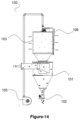
- a tremie dust collection unit (100) of the invention which has a grain receiving pit (tremie pit) and is used wherever it is desired to collect the grain dust and husk that comes out during the grain pouring process, is explained only as an example for a better understanding of the subject and without any limiting effect.
- the tremie dust collection unit (100) shown in Figure-1 has simpler equipment and structure compared to existing applications and systems.
- the said tremie dust collection unit (100) has a nozzle unit (106) that rotates 360° around a single filter unit (103) to clean the surface and is integrated into the cyclone (101) shown in Figure-2.
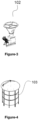
- the said tremie dust collection unit (100) contains an air lock (102) mounted on the cyclone (101) and shown in Figure-3.
- the said filter unit (103) shown in Figure-4 offers a new approach in terms of capturing the dust and cleaning the cloth filter (104).
- the nozzle unit (106) shown in Figure-5 is positioned on the said filter unit (103).
- the cloth filter (104) holding the dust in the said filter unit (103) and shown in Figure-6 has a larger surface area than the filters used in the existing state of the art and is easy to replace.
- a radial fan (105) is used to clean the said cloth filter (104).
- An electric motor (113) is placed at the top of the said filter unit (103).
- the said nozzle unit (106) shown in Figure-9 includes a dust capture unit (107) shown in Figure-7, which prevents dust from dispersing in the cyclone (101) during cleaning of the cloth filter (104) and delivers it to the air lock (102) as a closed circuit.
- the air passage coupling (108) shown in Figure-10 ensures that the air coming from the radial fan (105) shown in Figure-8 is transferred to the nozzle unit (106) and that the nozzle unit (106) rotates around the filter unit (103).
- On the upper part of the nozzle unit (106) shown in Figure-11 there is a sealing element (109) to transfer the air coming from the radial fan (105) to the nozzle unit (106) without losing pressure and flow, an inner sleeve (110) for connecting the air passage coupling (108) to the nozzle unit (106) and transferring the air from the radial fan (105) to the rotating nozzle unit (106), and there is a fixed outer sleeve (111) positioned on the rotating inner sleeve (110) to transfer the air to the nozzle unit (106), connected to the end of the air line coming from the radial fan (105) of the air passage coupling (108).
- the nozzle unit (106) shown in Figure-12a There is an air outlet section in the form of a hole extending from one end to the other on the nozzle unit (106) shown in Figure-12a.
- the said nozzle unit (106) has a conical cross-section with a wider nozzle cross-section at the top with a narrowing one at the bottom.
- the air entering from the wider part compared to the lower part comes out of the air outlet section along the nozzle unit (106) in the inner section that narrows downwards.
- the nozzle unit (106) shown in Figure-12b allows compressed air to be sent by rotating 360° to the surface of the entire filter unit (103) and at the same time, due to its construction, the air exits at an equal flow rate and pressure.
- the nozzle unit (106) is designed in such a way that the air coming from the radial fan (105) operates on whole surface of the cloth filter (104) at an equal pressure and flow rate.
- the section was narrowed towards the lower part and tapered towards the air outlet part.
- the narrowed section prevented more air flow to the lower part, and the tapered section prevented the air pressure from decreasing. In this way, homogeneous air pressure and flow rate were provided from the nozzle unit (106) throughout the entire section.
- the cleaning brushes (112) placed in contact with the cloth filter (104) and the lower funnel of the filter unit (103) shown in Figure-13 prevent the adhesion of especially high-humidity dust to the lower cone of the filter unit (103) and at the same time ensure that the surface of the cloth filter (104) is cleaned.
- the air lock (102) is installed in the cyclone (101) body, and then the filter unit (103) is mounted in the cyclone (101) body. After the installation of the filter unit (103), the assembly is completed by installing the radial fan (105) and the filter housing.
- Relatively massive particles move to the lower part of the cyclone (101) within the framework of the operation principle of the cyclone (101) and are expelled with the help of the air lock (102).
- the particles that the cyclone (101) cannot capture are transferred to the filter unit (103).
- the dust is kept by the cloth filter (104) and fresh air is supplied to the environment.
- the dust remaining on the cloth filter (104) is cleaned by means of compressed air provided to the cloth filter (104).
- Radial fan (105) was used as the air source.
- the generated air is transferred to the nozzle unit (106) via the air passage coupling (108).
- the said air passage coupling (108) is designed to allow the nozzle unit (106) to rotate 360° around the cloth filter (104).
- the air passage coupling (108) comprises inner sleeve (110), outer sleeve (111) and a sealing member (109).
- the inner sleeve (110) of the air passage coupling (108) is fixed to the upper part of the nozzle unit (106).
- the center of the inner sleeve (110) is positioned to be the center of rotation of the nozzle unit (106), which rotates around the cloth filter (104).
- the nozzle unit (106) is driven by an electric motor (113) mounted on the upper part of the filter system (103).
- the outer sleeve (111) of the air passage coupling (108) is located at the end of the compressed air line.
- the sealing member (109) is placed between the inner sleeve (110) and the outer sleeve (111). In this way, the inner sleeve (110) rotates inside the outer sleeve (111), allowing the nozzle unit (106) to rotate around the cloth filter (104). In addition, the sealing member (109) prevents compressed air from leaving the system.
- the pushed dust is trapped by the nozzle unit (106) and the synchronous dust capturing module (107).
- the dust capturing module(107) ensures that the dust that comes out during the cleaning of the cloth filter (104) reaches the air lock (102) without being affected by any situation in the indoor environment and is thrown out.
Landscapes
- Chemical & Material Sciences (AREA)
- Chemical Kinetics & Catalysis (AREA)
- Engineering & Computer Science (AREA)
- Mechanical Engineering (AREA)
- Cyclones (AREA)
Applications Claiming Priority (1)
| Application Number | Priority Date | Filing Date | Title |
|---|---|---|---|
| TR202118605 | 2021-11-26 |
Publications (1)
| Publication Number | Publication Date |
|---|---|
| EP4186582A1 true EP4186582A1 (de) | 2023-05-31 |
Family
ID=83898451
Family Applications (1)
| Application Number | Title | Priority Date | Filing Date |
|---|---|---|---|
| EP22197627.7A Withdrawn EP4186582A1 (de) | 2021-11-26 | 2022-09-26 | Mit dem zyklon integrierte tremisstaubsammeleinheit |
Country Status (1)
| Country | Link |
|---|---|
| EP (1) | EP4186582A1 (de) |
Cited By (1)
| Publication number | Priority date | Publication date | Assignee | Title |
|---|---|---|---|---|
| CN119075533A (zh) * | 2024-11-01 | 2024-12-06 | 温岭市千源环保科技有限公司 | 一种环保的建筑弥散尘土处理设备 |
Citations (5)
| Publication number | Priority date | Publication date | Assignee | Title |
|---|---|---|---|---|
| US4353722A (en) * | 1979-04-03 | 1982-10-12 | Gimag Aktiengesellschaft | Granular bed filter device including a regenerative granular bed cleaning apparatus |
| DE19882101T1 (de) * | 1997-02-07 | 2000-04-27 | Markku Vanhala | Reinigungsapparat für einen Filter eines Staubfiltergeräts |
| KR200370893Y1 (ko) * | 1998-12-19 | 2005-05-18 | 유니셈 주식회사 | 폐가스처리장치 |
| KR200463614Y1 (ko) * | 2010-09-02 | 2012-11-13 | 주식회사 삼천리 | 정압기 필터 재생장치 |
| CN108854325B (zh) * | 2018-07-27 | 2020-12-25 | 广东合创工程总承包有限公司 | 一种建筑施工除尘装置 |
-
2022
- 2022-09-26 EP EP22197627.7A patent/EP4186582A1/de not_active Withdrawn
Patent Citations (5)
| Publication number | Priority date | Publication date | Assignee | Title |
|---|---|---|---|---|
| US4353722A (en) * | 1979-04-03 | 1982-10-12 | Gimag Aktiengesellschaft | Granular bed filter device including a regenerative granular bed cleaning apparatus |
| DE19882101T1 (de) * | 1997-02-07 | 2000-04-27 | Markku Vanhala | Reinigungsapparat für einen Filter eines Staubfiltergeräts |
| KR200370893Y1 (ko) * | 1998-12-19 | 2005-05-18 | 유니셈 주식회사 | 폐가스처리장치 |
| KR200463614Y1 (ko) * | 2010-09-02 | 2012-11-13 | 주식회사 삼천리 | 정압기 필터 재생장치 |
| CN108854325B (zh) * | 2018-07-27 | 2020-12-25 | 广东合创工程总承包有限公司 | 一种建筑施工除尘装置 |
Cited By (1)
| Publication number | Priority date | Publication date | Assignee | Title |
|---|---|---|---|---|
| CN119075533A (zh) * | 2024-11-01 | 2024-12-06 | 温岭市千源环保科技有限公司 | 一种环保的建筑弥散尘土处理设备 |
Similar Documents
| Publication | Publication Date | Title |
|---|---|---|
| CN111296041B (zh) | 一种低扬尘的花生捡拾联合收获机 | |
| CN108160492A (zh) | 一种面粉加工过程中的除杂装置 | |
| CN116750530A (zh) | 一种一体式封闭型粮食输送机 | |
| CN110918440B (zh) | 粒径拣选装置 | |
| CN207446750U (zh) | 饲料清理装置 | |
| CN112718483B (zh) | 一种粮油加工用原料杂质去除筛选装置 | |
| EA044005B1 (ru) | Пылеулавливающее устройство-воронка, встроенное в циклонный пылеуловитель | |
| KR100891803B1 (ko) | 집진관 막힘 방지장치 | |
| KR101770508B1 (ko) | 분말 가공기 | |
| CN210202537U (zh) | 粮仓上料系统 | |
| CN210995256U (zh) | 一种饲料三级筛料机 | |
| CN106964545A (zh) | 一种家用小型粮食扬尘装置 | |
| CN209988746U (zh) | 一种晒场谷物收集设备 | |
| KR101765531B1 (ko) | 압축공기를 이용한 쌀 세척장치 | |
| CN217369218U (zh) | 一种小米清洗烘干设备 | |
| US2991883A (en) | Grain handling machine | |
| TR2021018605A2 (tr) | Si̇klona entegre tremi̇ toz toplama üni̇tesi̇ | |
| CN112265776A (zh) | 一种干燥除杂一体化的粮食输送机 | |
| CN218014145U (zh) | 一种种子清选机 | |
| CN210876273U (zh) | 一种物料杂质分离装置 | |
| CN208261032U (zh) | 旋风式除尘装置 | |
| CN210328908U (zh) | 一种畜牧用喂料装置 | |
| CN223234410U (zh) | 一种用于茶叶生产加工的除杂装置 | |
| CN222573283U (zh) | 一种具有筛渣功能的茶叶输送机 | |
| KR20220052533A (ko) | 자주식 계사청소기용 계분 분쇄 및 이송모듈 |
Legal Events
| Date | Code | Title | Description |
|---|---|---|---|
| PUAI | Public reference made under article 153(3) epc to a published international application that has entered the european phase |
Free format text: ORIGINAL CODE: 0009012 |
|
| STAA | Information on the status of an ep patent application or granted ep patent |
Free format text: STATUS: THE APPLICATION HAS BEEN PUBLISHED |
|
| AK | Designated contracting states |
Kind code of ref document: A1 Designated state(s): AL AT BE BG CH CY CZ DE DK EE ES FI FR GB GR HR HU IE IS IT LI LT LU LV MC MK MT NL NO PL PT RO RS SE SI SK SM TR |
|
| STAA | Information on the status of an ep patent application or granted ep patent |
Free format text: STATUS: THE APPLICATION IS DEEMED TO BE WITHDRAWN |
|
| 18D | Application deemed to be withdrawn |
Effective date: 20231201 |