EP4187111B1 - Agencement de verrouillage permettant de connecter et d'interverrouiller des barres au niveau d'un noeud à l'intérieur d'un treillis - Google Patents
Agencement de verrouillage permettant de connecter et d'interverrouiller des barres au niveau d'un noeud à l'intérieur d'un treillis Download PDFInfo
- Publication number
- EP4187111B1 EP4187111B1 EP21211212.2A EP21211212A EP4187111B1 EP 4187111 B1 EP4187111 B1 EP 4187111B1 EP 21211212 A EP21211212 A EP 21211212A EP 4187111 B1 EP4187111 B1 EP 4187111B1
- Authority
- EP
- European Patent Office
- Prior art keywords
- actuation
- locking
- central node
- central
- node bearing
- Prior art date
- Legal status (The legal status is an assumption and is not a legal conclusion. Google has not performed a legal analysis and makes no representation as to the accuracy of the status listed.)
- Active
Links
Images



Classifications
-
- B—PERFORMING OPERATIONS; TRANSPORTING
- B64—AIRCRAFT; AVIATION; COSMONAUTICS
- B64C—AEROPLANES; HELICOPTERS
- B64C1/00—Fuselages; Constructional features common to fuselages, wings, stabilising surfaces or the like
- B64C1/06—Frames; Stringers; Longerons ; Fuselage sections
- B64C1/061—Frames
-
- F—MECHANICAL ENGINEERING; LIGHTING; HEATING; WEAPONS; BLASTING
- F16—ENGINEERING ELEMENTS AND UNITS; GENERAL MEASURES FOR PRODUCING AND MAINTAINING EFFECTIVE FUNCTIONING OF MACHINES OR INSTALLATIONS; THERMAL INSULATION IN GENERAL
- F16B—DEVICES FOR FASTENING OR SECURING CONSTRUCTIONAL ELEMENTS OR MACHINE PARTS TOGETHER, e.g. NAILS, BOLTS, CIRCLIPS, CLAMPS, CLIPS OR WEDGES; JOINTS OR JOINTING
- F16B7/00—Connections of rods or tubes, e.g. of non-circular section, mutually, including resilient connections
- F16B7/02—Connections of rods or tubes, e.g. of non-circular section, mutually, including resilient connections with conical parts
- F16B7/025—Connections of rods or tubes, e.g. of non-circular section, mutually, including resilient connections with conical parts with the expansion of an element inside the tubes due to axial movement towards a wedge or conical element
-
- E—FIXED CONSTRUCTIONS
- E01—CONSTRUCTION OF ROADS, RAILWAYS, OR BRIDGES
- E01D—CONSTRUCTION OF BRIDGES, ELEVATED ROADWAYS OR VIADUCTS; ASSEMBLY OF BRIDGES
- E01D19/00—Structural or constructional details of bridges
-
- E—FIXED CONSTRUCTIONS
- E04—BUILDING
- E04B—GENERAL BUILDING CONSTRUCTIONS; WALLS, e.g. PARTITIONS; ROOFS; FLOORS; CEILINGS; INSULATION OR OTHER PROTECTION OF BUILDINGS
- E04B1/00—Constructions in general; Structures which are not restricted either to walls, e.g. partitions, or floors or ceilings or roofs
- E04B1/38—Connections for building structures in general
- E04B1/58—Connections for building structures in general of bar-shaped building elements
-
- E—FIXED CONSTRUCTIONS
- E04—BUILDING
- E04B—GENERAL BUILDING CONSTRUCTIONS; WALLS, e.g. PARTITIONS; ROOFS; FLOORS; CEILINGS; INSULATION OR OTHER PROTECTION OF BUILDINGS
- E04B1/00—Constructions in general; Structures which are not restricted either to walls, e.g. partitions, or floors or ceilings or roofs
- E04B1/38—Connections for building structures in general
- E04B1/58—Connections for building structures in general of bar-shaped building elements
- E04B1/5825—Connections for building structures in general of bar-shaped building elements with a closed cross-section
- E04B1/5837—Connections for building structures in general of bar-shaped building elements with a closed cross-section of substantially circular form
- E04B1/585—Connections for building structures in general of bar-shaped building elements with a closed cross-section of substantially circular form with separate connection devices
-
- F—MECHANICAL ENGINEERING; LIGHTING; HEATING; WEAPONS; BLASTING
- F16—ENGINEERING ELEMENTS AND UNITS; GENERAL MEASURES FOR PRODUCING AND MAINTAINING EFFECTIVE FUNCTIONING OF MACHINES OR INSTALLATIONS; THERMAL INSULATION IN GENERAL
- F16B—DEVICES FOR FASTENING OR SECURING CONSTRUCTIONAL ELEMENTS OR MACHINE PARTS TOGETHER, e.g. NAILS, BOLTS, CIRCLIPS, CLAMPS, CLIPS OR WEDGES; JOINTS OR JOINTING
- F16B7/00—Connections of rods or tubes, e.g. of non-circular section, mutually, including resilient connections
- F16B7/04—Clamping or clipping connections
- F16B7/044—Clamping or clipping connections for rods or tubes being in angled relationship
- F16B7/0446—Clamping or clipping connections for rods or tubes being in angled relationship for tubes using the innerside thereof
-
- F—MECHANICAL ENGINEERING; LIGHTING; HEATING; WEAPONS; BLASTING
- F16—ENGINEERING ELEMENTS AND UNITS; GENERAL MEASURES FOR PRODUCING AND MAINTAINING EFFECTIVE FUNCTIONING OF MACHINES OR INSTALLATIONS; THERMAL INSULATION IN GENERAL
- F16B—DEVICES FOR FASTENING OR SECURING CONSTRUCTIONAL ELEMENTS OR MACHINE PARTS TOGETHER, e.g. NAILS, BOLTS, CIRCLIPS, CLAMPS, CLIPS OR WEDGES; JOINTS OR JOINTING
- F16B7/00—Connections of rods or tubes, e.g. of non-circular section, mutually, including resilient connections
- F16B7/18—Connections of rods or tubes, e.g. of non-circular section, mutually, including resilient connections using screw-thread elements
- F16B7/185—Connections of rods or tubes, e.g. of non-circular section, mutually, including resilient connections using screw-thread elements with a node element
-
- E—FIXED CONSTRUCTIONS
- E04—BUILDING
- E04B—GENERAL BUILDING CONSTRUCTIONS; WALLS, e.g. PARTITIONS; ROOFS; FLOORS; CEILINGS; INSULATION OR OTHER PROTECTION OF BUILDINGS
- E04B1/00—Constructions in general; Structures which are not restricted either to walls, e.g. partitions, or floors or ceilings or roofs
- E04B1/38—Connections for building structures in general
- E04B1/58—Connections for building structures in general of bar-shaped building elements
- E04B1/5825—Connections for building structures in general of bar-shaped building elements with a closed cross-section
- E04B2001/5856—Connections for building structures in general of bar-shaped building elements with a closed cross-section using the innerside thereof
-
- F—MECHANICAL ENGINEERING; LIGHTING; HEATING; WEAPONS; BLASTING
- F16—ENGINEERING ELEMENTS AND UNITS; GENERAL MEASURES FOR PRODUCING AND MAINTAINING EFFECTIVE FUNCTIONING OF MACHINES OR INSTALLATIONS; THERMAL INSULATION IN GENERAL
- F16B—DEVICES FOR FASTENING OR SECURING CONSTRUCTIONAL ELEMENTS OR MACHINE PARTS TOGETHER, e.g. NAILS, BOLTS, CIRCLIPS, CLAMPS, CLIPS OR WEDGES; JOINTS OR JOINTING
- F16B2/00—Friction-grip releasable fastenings
- F16B2/02—Clamps, i.e. with gripping action effected by positive means other than the inherent resistance to deformation of the material of the fastening
- F16B2/14—Clamps, i.e. with gripping action effected by positive means other than the inherent resistance to deformation of the material of the fastening using wedges
-
- Y—GENERAL TAGGING OF NEW TECHNOLOGICAL DEVELOPMENTS; GENERAL TAGGING OF CROSS-SECTIONAL TECHNOLOGIES SPANNING OVER SEVERAL SECTIONS OF THE IPC; TECHNICAL SUBJECTS COVERED BY FORMER USPC CROSS-REFERENCE ART COLLECTIONS [XRACs] AND DIGESTS
- Y10—TECHNICAL SUBJECTS COVERED BY FORMER USPC
- Y10T—TECHNICAL SUBJECTS COVERED BY FORMER US CLASSIFICATION
- Y10T403/00—Joints and connections
- Y10T403/34—Branched
- Y10T403/341—Three or more radiating members
- Y10T403/342—Polyhedral
Definitions
- the present invention pertains to a locking arrangement for connecting and interlocking rods at a node within a framework.
- Beams, joists, rods and frames for construction work for example in aeronautics, civil engineering or architecture, are designed to withstand bending forces acting perpendicular to their direction of extension. These elements are often connected with each other at joints, also referred to as nodes, to build two- or three-dimensional frameworks. Individual connections in these frameworks may be flexurally rigid or articulated, e.g. by means of pivots or rotary joints. In some applications an articulated connection may be preferred as it may help to compensate for existing tolerances and to avoid eccentricity moments.
- the mechanism used for this purpose should not only be lightweight but also simple to handle in order to safe lead time and assembly costs.
- Prior art document DE 10 2017 131 130 A1 pertains to an exemplary system for attaching a component to a fuselage structure.
- Prior art document DE 20 2019 106 029 U1 describes screwable devices with retractable thread segments, which are used to secure a workpiece on a device, on a workbench or the like.
- a locking arrangement for connecting and interlocking rods at a node within a framework comprises several connection rods; and a central node bearing configured to be engaged from different directions by each of the connection rods at respective mounting ports by plugging each connection rod onto a respective mounting port, wherein the central node bearing is configured with at least one locking element at each mounting port to be actuated between a locked state, in which the at least one locking element resides in an outward position and the respective connection rod plugged onto the respective mounting port is clutched to the central node bearing by the at least one locking element, and an unlocked locked state, in which the at least one locking element resides in an inward position and the respective connection rod is released from the central node bearing.
- one idea of the present invention is to provide a single locking point for several connection rods with a central locking mechanism to keep the assembly as simple as possible and thus to reduce installation time as well as weight.
- the mounting ports may be arranged in a plane, e.g. circularly and/or radially around a center of the node bearing. For example, four mounting ports may be positioned in a circle around the center evenly spaced at 90°.
- mounting ports may also be used to couple one or several interconnecting rods at an oblique angle to the node bearing relatively to the other interconnecting rods.
- interconnecting rods may be coupled to the node bearing in an almost arbitrary manner in three dimensions along a spherical shell around the center of the node bearing.
- the mounting ports may be arranged on the central node bearing such that the connection rods are oriented towards a common center point of the central node bearing when engaged to the mounting ports.
- the mounting ports and thus the interconnecting rods may follow a starlike configuration around a center of the node bearing.
- the locking elements may be configured with a toothed locking surface configured to engage a complementary formed counter locking surface on the respective connection rod.
- each locking element may be configured as a plate with a toothed surface.
- the connection rods may be formed hollow at least at one end (i.e. pipe-like) and may have an inner surface or several surface portions configured with openings or slots to engage with the teeth of the locking elements such that a form fit may be achieved between both elements.
- the central node bearing is provided with a central actuation system configured to move actuation pins axially into and out of respective mounting ports to actuate the respective at least one locking element between the locked state and the unlocked state.
- ball lock pins also called locking pins, safety pins or quick release pins, which are widely used to quickly and easily join and fasten components without the need for tools. Pressing a button in the head of such a pin releases a ball lock allowing the pin to be pushed through a hole in the parts to be joined. When the spring-loaded button is released, the balls lock automatically thereby closing the fastening.
- the locking elements being actuated centrally by the actuation pins serve the same purpose as the balls in case of ball lock pins. However, in case of the present invention, a plurality of rods may be locked/unlocked at the same time in this manner.
- the actuation pins may be mounted spring-loaded within the mounting ports such that the respective locking elements are normally locked when the connection rods engage the mounting ports.
- This embodiment provides advantages with regards to safety, as the actuation mechanism has to be activated in order to release the connection rods from the central node bearing. This means that the rods are firmly locked to the node by default.
- each locking element may rest positionally fixed along an axial direction with an actuation surface radially outside on the respective actuation pin at a complementary formed counter actuation surface such that axial movement of the actuation pin into and out of the respective mounting port moves the locking element radially outwards or inwards from the actuation pin, respectively, to switch between the locked state and the unlocked state.
- the locking elements may be arranged within corresponding holes inside a housing of the mounting ports, e.g. slits in the outer wall of a hollow cylindrical enclosure.
- the actuation pins may be movable along an axial direction within the interior space of the mounting port below the respective openings or slits for the locking elements. If the actuation surfaces of both the locking elements and the actuation pins are formed adequately, relative sliding movement between the elements may push the locking elements radially outwards and against the respective connection rod, thereby engaging the connection rod by means of teeth or similar.
- the central actuation system comprises a rotatable actuation element rotatably mounted in a center portion of the central node bearing and engaging at least one of the actuation pins with a corresponding radial ramp portion.
- the radial ramp portion is wedge-shaped in a circumferential direction around the rotational axis of the rotatable actuation element such that the corresponding actuation pin is moved into and out of the corresponding mounting port by the corresponding radial ramp portion under rotation of the rotatable actuation element.
- the rotatable actuation element may have several such radial ramp portions arranged along a circumferential direction around the axis of rotation of the actuation element.
- the actuation element may push several actuation pins that point radially outwards at the same time and thereby actuate the respective locking mechanisms for several connection rods engaging the node bearing in a star-like configuration.
- At least one of the radial ramp portions may have a conically curved radial surface to engage an actuation pin oriented inclined with respect to a radial direction around the rotation axis of the rotatable actuation element.
- the actuation pins and thus the connection rods cannot only be coupled to the node bearing in a radial configuration.
- one or several of the actuation pins may be arranged under an oblique angle to the axis of rotation of the rotatable actuation element.
- the radial surface of the ramp portions may be shaped adequately so that also actuation pins under an inclined angle may be actuated by rotating the actuation element in the center.
- the central actuation system may comprise a turn knob having an external thread configured to engage an internal thread of the rotatable actuation element along the rotational axis of the rotatable actuation element, wherein the turn knob is configured to move an actuation pin oriented axially along the rotational axis of the rotatable actuation element into and out of a corresponding mounting port by moving in and out of the internal thread, respectively.
- This embodiment thus also makes it possible to actuate pins along the rotational axis of the central actuation element.
- the turn knob may be adapted to be turned by a first turning angle within the rotatable actuation element to push the axially oriented actuation pin into the unlocked position and subsequently be turned by a second turning angle jointly with the rotatable actuation element to actuate the further actuation pins via rotation of the rotatable actuation element.
- all actuation pins can be actuated independently of their orientation merely by turning the turn knob. First the axially oriented actuation pin is pushed into its respective mounting port by turning the turn knob by the first turning angle. As soon as the actuation pins reaches an end stop within the mounting port, further rotation of the turn knob may cause rotation of the actuation element, which in turn will then actuate the remaining actuation pins.
- the central actuation system may be on pneumatic and/or hydraulic expansion using a fluid as actuation medium to move the actuation pins into and out of the corresponding mounting ports.
- pressurized air can be used as actuation medium to push the actuation pins outwards from the center of the node bearing.
- Such an hydraulic and/or pneumatic approach may have benefits, e.g. to actuate pins in any direction, that is, also under oblique angles, without having to provide a mechanical rotation element with potentially complex outer shape.
- the central actuation system comprises an electroactive polymer as actuation medium to move the actuation pins into and out of the corresponding mounting ports.
- a core of the node bearing may include a component made of an electroactive material that expands under application of electricity, which then may be used to push the actuation pins outwards from the center of the node bearing.
- the central actuation comprises a rubber block as actuation medium to move the actuation pins into and out of the corresponding mounting ports.
- Each actuation pin is coupled to the rubber block via a corresponding push-plate, wherein the rubber block is further coupled to an actuation plate configured to actuate movement of the actuation pins outwards from the rubber block by being pushed into the rubber block.
- metal plates may be attached to a rubber block (flexible yet not very compressible), which keep the actuation pins from pressing into the rubber.
- a rubber block flexible yet not very compressible
- the other plates When pressure is applied to one of these plates, the other plates necessarily move. Similar to a hydraulic drive, the pressure will spread in all directions and thus may move all pins at the same time.
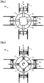
- Figure 1 schematically depicts a cross-sectional view of a locking arrangement 10 according to an embodiment of the invention in an unlocked state.
- Fig. 2 shows the locking arrangement 10 of Fig. 1 in a locked state.
- frameworks in aircraft include connection rods for bracing a fuselage structure of an aircraft, structurally reinforcing a fuselage structure and/or for fastening a component on the fuselage structure.
- connection rods 1 generally comprise several connection rods 1 and a central node bearing 2 configured to be engaged from different directions by each of the connection rods 1 at respective mounting ports 3 by plugging each connection rod 1 onto a respective mounting port 3.
- the central node bearing 2 is configured with at least one locking element 4 at each mounting port 3 to be actuated between a locked state, in which the at least one locking element 4 resides in an outward position and the respective connection rod 1 plugged onto the respective mounting port 3 is clutched to the central node bearing 2 by the at least one locking element 4, and an unlocked locked state, in which the at least one locking element 4 resides in an inward position and the respective connection rod 1 is released from the central node bearing 2.
- the mounting ports 3 are arranged on the central node bearing 2 such that the connection rods 1 are oriented towards a common center point of the central node bearing 2 when engaged to the mounting ports 3.
- Figs. 1 and 2 show an exemplary embodiment of this general configuration.
- the rods 1 may be hollow (tubular) elongated structures or may at least have a hollow portion at one end, at which the respective rods 1 may be plugged onto the mounting ports 3.
- the locking elements 4 are configured with a toothed locking surface 4a configured to engage a complementary formed counter locking surface 1a on the respective connection rods 1.
- the central node bearing 2 is provided with a central actuation system 5 configured to move actuation pins 6 axially into and out of respective mounting ports 3 to actuate the respective at least one locking element 4 between the locked state and the unlocked state.
- the central actuation system 5 follows a mechanical approach to move four connection rods 6 between locked and unlocked states. More specifically, the central actuation system 5 comprises a rotatable actuation element 7 rotatably mounted in a center portion of the central node bearing 2 and engaging the four actuation pins 6 with corresponding radial ramp portions 7a.
- the radial ramp portions 7a are wedge-shaped in a circumferential direction around the rotation axis of the rotatable actuation element 7 (pointing into the drawing) such that the corresponding actuation pin 6 is moved into and out of the corresponding mounting port 3 by the corresponding radial ramp portion 7a under rotation of the rotatable actuation element 7.
- Figs. 1 and 2 thus has a normally unlocked configuration, i.e. the pins 6 have to be pushed outwards from the center of the node bearing to close a form fit between the toothed locking surfaces 4a of the locking elements and the toothed counter locking surface of the connection rods 1a (cf. arrows in Fig. 2 ) and thereby lock the arrangement.
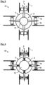
- Figs. 3 and 4 schematically show an alternative embodiment, in which the central actuation system 5 comprises a core of electroactive polymer 12 as actuation medium to move the actuation pins 6 into and out of the corresponding mounting ports 3.
- the electroactive polymer 12 may expand under the application of electric power, which will then push the actuation pins 6 outward from the center of the node bearing 2, thereby closing the locking mechanism between the locking elements 4 and the connection rods 1.
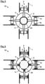
- Figs. 5 and 6 show an alternative embodiment, in which the central actuation system 5 is based on hydraulic expansion using a gas or a liquid as actuation medium to move the actuation pins 6 into and out of the corresponding mounting ports 3.
- pressurized air may be used for this purpose, as it is typically widely available at construction sites.
- the actuation rods 6 are positioned on shell segments 24, which form a closed volume in the unlocked state ( Fig. 5 ) and can be moved outwards by applying pressure to the fluid 11, thereby locking the connection rods 1 to the mounting ports 3.
- a plug 25 may be entered between the shell segments 24 to keep them from falling back to the center.
- actuation pins 6 in this case are spring-loaded within the mounting ports 3 such that the respective locking elements 4 are normally locked when the connection rods 1 engage the mounting ports 3. This provision makes the arrangement safer and thus better suited for safety relevant applications, e.g. in the aerospace sector.
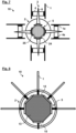
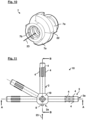
- the central node bearing 2 has a rigid node housing 19 surrounding a center portion 2a and five elongated hollow mounting ports 3. Four of them are arranged under 90° with respect to each other (three in a horizontal plane in Fig. 9 , one vertically upright with respect to these). A fifth one is oriented in the horizontal plane at an inclined angle with respect to the others.
- Each mounting port 3 has four port holes 20 in its outer walls to receive the locking elements 4 as well as a port end hole 3a at a distal end to receive a respective connection pin 6, a spring 16 and finally a cap 17 to shut off the assembly.
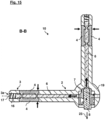
- Each locking element rests 4 with an actuation surface 4b radially outside on the respective actuation pin 6 at a complementary formed counter actuation surface 6a such that axial movement of the actuation pin 6 into and out of the respective mounting port 3 moves the locking element 4 radially outwards or inwards from the actuation pin 6, respectively.
- the locking elements 4 of this embodiment have two pins on their respective actuation surfaces 4b, whereas the actuation pins 6 have two correspondingly formed grooves on their counter actuation surfaces 6a.
- the pins of the locking elements 4 will enter the grooves at some point, thereby bringing the locking elements 4 closer to the actuation pins 6, which thus can be used to lock and unlock the arrangement (cf. Figs. 13 and 15 in particular).
- Fig. 9 two different types of locking elements 4 are shown in Fig. 9 .
- One type has a toothed locking surface 4a that is covered by a plurality of equally spaced narrow teeth with a distance that basically corresponds to the width of the teeth.
- the other one has only three teeth arranged on the locking surface 4a with a distance much larger than their width, thereby leaving some free play for the mounting process of the connection rods 1, which may be provided with a counter locking surface 1a having respectively formed grooves (cf. Figs. 12 and 13 , where only on exemplary connection rod 1 is shown).
- the center portion 2a of the node bearing 2 is configured to receive a rotatable actuation element 7 similarly designed as the one in Figs. 1 and 2 , which is mounted inside the center portion by means of a bearing ring 29, wherein a mounting pin 18 introduced through a mounting hole 26 in the bearing ring 29 enters a mounting slot 21 in the actuation element 7 to couple it to the bearing ring 29.
- the mounting slot 21 is elongated in a circumferential direction of the actuation element 7 so that the actuation element 7 can be rotated against the bearing ring 29 to some extend.
- the actuation element 7 has a first disk-like portion with three radial ramp portions 7a for actuating three of the actuation pins 6, namely the vertical one as well as the left and right horizontal ones in Fig. 9 .
- the actuation element 7 has a second disk-like portion with another radial ramp portion 7a having a conically curved radial surface to engage an actuation pin 6 inclined with respect to a radial direction around the rotation axis 23 of the rotatable actuation element (in the back on the left of the actuation element 7 in Fig.
- actuation element 9 which is a front view of the actuation element 7, and in the lower right in the front of Fig. 10 , which is a back view of the actuation element 7).
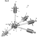
- the depicted actuation element is in fact able to actuate four of the five actuation pins 6 merely by rotating around its rotation axis 23 (cf. Figs. 13 , 15 and 18 in particular).
- Ramp edges 22 of the radial ramp portions 7a may serve as dedicated stops for the actuation pins 6 against the actuation element 7 in the locked configuration.
- the central actuation system 5 further comprises a turn knob 8 having an external thread 8a configured to engage an internal thread 7b of the rotatable actuation element 7 along the rotation axis 23 of the rotatable actuation element 7.
- the turn knob 8 is configured to move the actuation pin 6 oriented axially along the rotation axis 23 of the rotatable actuation element 7 into and out of a corresponding mounting port 3 by moving in and out of the internal thread 7b, respectively (the mounting port 3 pointing to the back in Fig. 9 ).
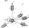
- the turn knob 8 is adapted to be turned by a first turning angle ⁇ within the rotatable actuation element 7 to push the axially oriented actuation pin 6 into the unlocked position and subsequently be turned by a second turning angle ⁇ jointly with the rotatable actuation element 7 to actuate the further actuation pins 6 via rotation of the rotatable actuation element 7.
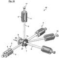
- Fig. 16 shows the default (normal) configuration of the arrangement 10, in which all connection rods 1 are locked to the mounting ports 3 (cf. locking elements 4 at each mounting port in Fig. 16 , which are expanded with respect to each other).
- the springs 16 provide a pre-load against any movement of the actuation pins 6 outwards into the mounting ports 3 such that the arrangement is normally closed (the actuation surfaces 4b and counter actuation surfaces 6a as well as the port holes 20 and actuation pin 6 dimensions and geometries need to be adjusted to each other in order to ensure this).
- a dedicated stop pin 27 may be provided that defines the maximum turning angle of the actuation element 7.
- connection rods 1 can be removed from the node bearing 2.
- the turn knob 8 By rotating the turn knob 8 back by 250°, the locked configuration can be reestablished in a simple manner.
Landscapes
- Engineering & Computer Science (AREA)
- General Engineering & Computer Science (AREA)
- Mechanical Engineering (AREA)
- Architecture (AREA)
- Civil Engineering (AREA)
- Structural Engineering (AREA)
- Physics & Mathematics (AREA)
- Electromagnetism (AREA)
- Aviation & Aerospace Engineering (AREA)
- Pivots And Pivotal Connections (AREA)
- Mutual Connection Of Rods And Tubes (AREA)
Claims (10)
- Agencement de verrouillage (10) pour connecter et interverrouiller des tiges au niveau d'un noeud à l'intérieur d'une ossature, l'agencement de verrouillage comprenant :plusieurs tiges de connexion (1) ; etun palier de noeud central (2) configuré pour être mis en prise à partir de différentes directions par chacune des tiges de connexion (1) au niveau d'orifices de montage (3) respectifs en enfichant chaque tige de connexion (1) sur un orifice de montage (3) respectif, dans lequel le palier de noeud central (2) est configuré avec au moins un élément de verrouillage (4) au niveau de chaque orifice de montage (3) à actionner entre un état verrouillé, dans lequel l'au moins un élément de verrouillage (4) réside dans une position vers l'extérieur et la tige de connexion (1) respective enfichée sur l'orifice de montage (3) respectif est en prise avec le palier de noeud central (2) par l'au moins un élément de verrouillage (4), et un état déverrouillé, dans lequel l'au moins un élément de verrouillage (4) réside dans une position vers l'intérieur et la tige de connexion (1) respective est libérée du palier de noeud central (2) ;dans lequel le palier de noeud central (2) est pourvu d'un système d'actionnement central (5) configuré pour déplacer des broches d'actionnement (6) axialement dans et hors d'orifices de montage (3) respectifs pour actionner l'au moins un élément de verrouillage (4) respectif entre l'état verrouillé et l'état déverrouillé ;caractérisé en ce quele système d'actionnement central (5) comprend un élément d'actionnement rotatif (7) monté de manière rotative dans une partie centrale (2a) du palier de noeud central (2) et mettant en prise au moins l'une des broches d'actionnement (6) avec une partie de rampe radiale (7a) correspondante, la partie de rampe radiale (7a) étant en forme de coin dans une direction circonférentielle autour de l'axe de rotation (23) de l'élément d'actionnement rotatif (7) de telle sorte que la broche d'actionnement (6) correspondante est déplacée dans et hors de l'orifice de montage (3) correspondant par la partie de rampe radiale (7a) correspondante sous la rotation de l'élément d'actionnement rotatif (7).
- Agencement de verrouillage (10) selon la revendication 1, dans lequel les orifices de montage (3) sont agencés sur le palier de noeud central (2) de telle sorte que les tiges de connexion (1) sont orientées vers un point central commun du palier de noeud central (2) lorsqu'elles sont mises en prise avec les orifices de montage (3).
- Agencement de verrouillage (10) selon la revendication 1 ou 2, dans lequel les éléments de verrouillage (4) sont configurés avec une surface de verrouillage à dents (4a) configurée pour mettre en prise une contre-surface de verrouillage formée de manière complémentaire (1a) sur la tige de connexion (1) respective.
- Agencement de verrouillage (10) selon l'une des revendications 1 à 3, dans lequel les broches d'actionnement (6) sont montées sur ressort à l'intérieur des orifices de montage (3) de telle sorte que les éléments de verrouillage (4) respectifs sont normalement verrouillés lorsque les tiges de connexion (1) mettent en prise les orifices de montage (3).
- Agencement de verrouillage (10) selon l'une des revendications 1 à 4, dans lequel chaque élément de verrouillage (4) repose fixé en position le long d'une direction axiale avec une surface d'actionnement (4b) radialement à l'extérieur sur la broche d'actionnement (6) respective au niveau d'une contre-surface d'actionnement formée de manière complémentaire (6a) de telle sorte qu'un mouvement axial de la broche d'actionnement (6) dans et hors de l'orifice de montage (3) respectif déplace l'élément de verrouillage (4) radialement vers l'extérieur ou vers l'intérieur à partir de la broche d'actionnement (6), respectivement, pour basculer entre l'état verrouillé et l'état déverrouillé.
- Agencement de verrouillage (10) selon l'une des revendications 1 à 5, dans lequel au moins l'une des parties de rampe radiale (7a) a une surface radiale incurvée de manière conique pour mettre en prise une broche d'actionnement (6) orientée de manière inclinée par rapport à une direction radiale autour de l'axe de rotation (23) de l'élément d'actionnement rotatif (7).
- Agencement de verrouillage (10) selon l'une des revendications 1 à 6, dans lequel le système d'actionnement central (5) comprend un bouton rotatif (8) ayant un filetage externe (8a) configuré pour mettre en prise un filetage interne (7b) de l'élément d'actionnement rotatif (7) le long de l'axe de rotation (23) de l'élément d'actionnement rotatif (7), dans lequel le bouton rotatif (8) est configuré pour déplacer une broche d'actionnement (6) orientée axialement le long de l'axe de rotation (23) de l'élément d'actionnement rotatif (7) dans et hors d'un orifice de montage (3) correspondant en se déplaçant dans et hors du filetage interne (7b), respectivement.
- Agencement de verrouillage (10) selon la revendication 7, dans lequel le bouton rotatif (8) est adapté pour être tourné d'un premier angle de rotation (α) à l'intérieur de l'élément d'actionnement rotatif (7) pour pousser la broche d'actionnement (6) orientée axialement dans la position déverrouillée et être ensuite tourné d'un second angle de rotation (β) conjointement avec l'élément d'actionnement rotatif (7) pour actionner les autres broches d'actionnement (6) par l'intermédiaire de la rotation de l'élément d'actionnement rotatif (7).
- Agencement de verrouillage (10) pour connecter et interverrouiller des tiges au niveau d'un noeud à l'intérieur d'une ossature, l'agencement de verrouillage comprenant :plusieurs tiges de connexion (1) ; etun palier de noeud central (2) configuré pour être mis en prise à partir de différentes directions par chacune des tiges de connexion (1) au niveau d'orifices de montage (3) respectifs en enfichant chaque tige de connexion (1) sur un orifice de montage (3) respectif, dans lequel le palier de noeud central (2) est configuré avec au moins un élément de verrouillage (4) au niveau de chaque orifice de montage (3) à actionner entre un état verrouillé, dans lequel l'au moins un élément de verrouillage (4) réside dans une position vers l'extérieur et la tige de connexion (1) respective enfichée sur l'orifice de montage (3) respectif est en prise avec le palier de noeud central (2) par l'au moins un élément de verrouillage (4), et un état déverrouillé, dans lequel l'au moins un élément de verrouillage (4) réside dans une position vers l'intérieur et la tige de connexion (1) respective est libérée du palier de noeud central (2) ;dans lequel le palier de noeud central (2) est pourvu d'un système d'actionnement central (5) configuré pour déplacer des broches d'actionnement (6) axialement dans et hors d'orifices de montage (3) respectifs pour actionner l'au moins un élément de verrouillage (4) respectif entre l'état verrouillé et l'état déverrouillé ;caractérisé en ce quele système d'actionnement central (5) comprend un polymère électroactif (12) en tant que support d'actionnement pour déplacer les broches d'actionnement (6) dans et hors des orifices de montage (3) correspondants.
- Agencement de verrouillage (10) pour connecter et interverrouiller des tiges au niveau d'un noeud à l'intérieur d'une ossature, l'agencement de verrouillage comprenant :plusieurs tiges de connexion (1) ; etun palier de noeud central (2) configuré pour être mis en prise à partir de différentes directions par chacune des tiges de connexion (1) au niveau d'orifices de montage (3) respectifs en enfichant chaque tige de connexion (1) sur un orifice de montage (3) respectif, dans lequel le palier de noeud central (2) est configuré avec au moins un élément de verrouillage (4) au niveau de chaque orifice de montage (3) à actionner entre un état verrouillé, dans lequel l'au moins un élément de verrouillage (4) réside dans une position vers l'extérieur et la tige de connexion (1) respective enfichée sur l'orifice de montage (3) respectif est en prise avec le palier de noeud central (2) par l'au moins un élément de verrouillage (4), et un état déverrouillé, dans lequel l'au moins un élément de verrouillage (4) réside dans une position vers l'intérieur et la tige de connexion (1) respective est libérée du palier de noeud central (2) ;dans lequel le palier de noeud central (2) est pourvu d'un système d'actionnement central (5) configuré pour déplacer des broches d'actionnement (6) axialement dans et hors d'orifices de montage (3) respectifs pour actionner l'au moins un élément de verrouillage (4) respectif entre l'état verrouillé et l'état déverrouillé ;caractérisé en ce quele système d'actionnement central (5) comprend un bloc de caoutchouc (13) en tant que support d'actionnement pour déplacer les broches d'actionnement (6) dans et hors des orifices de montage (3) correspondants, dans lequel chaque broche d'actionnement (6) est couplée au bloc de caoutchouc (13) par l'intermédiaire d'une plaque de poussée (14) correspondante, dans lequel le bloc de caoutchouc (13) est en outre couplé à une plaque d'actionnement (15) configurée pour actionner le mouvement des broches d'actionnement (6) vers l'extérieur à partir du bloc de caoutchouc (13) en étant poussée dans le bloc de caoutchouc (13).
Priority Applications (3)
| Application Number | Priority Date | Filing Date | Title |
|---|---|---|---|
| EP21211212.2A EP4187111B1 (fr) | 2021-11-30 | 2021-11-30 | Agencement de verrouillage permettant de connecter et d'interverrouiller des barres au niveau d'un noeud à l'intérieur d'un treillis |
| CN202211271458.1A CN116198712A (zh) | 2021-11-30 | 2022-10-18 | 用于连接和互锁框架内的节点处的杆的锁定布置 |
| US18/071,242 US12553458B2 (en) | 2021-11-30 | 2022-11-29 | Locking arrangement for connecting and interlocking struts at a node within a framework |
Applications Claiming Priority (1)
| Application Number | Priority Date | Filing Date | Title |
|---|---|---|---|
| EP21211212.2A EP4187111B1 (fr) | 2021-11-30 | 2021-11-30 | Agencement de verrouillage permettant de connecter et d'interverrouiller des barres au niveau d'un noeud à l'intérieur d'un treillis |
Publications (2)
| Publication Number | Publication Date |
|---|---|
| EP4187111A1 EP4187111A1 (fr) | 2023-05-31 |
| EP4187111B1 true EP4187111B1 (fr) | 2024-07-24 |
Family
ID=78824852
Family Applications (1)
| Application Number | Title | Priority Date | Filing Date |
|---|---|---|---|
| EP21211212.2A Active EP4187111B1 (fr) | 2021-11-30 | 2021-11-30 | Agencement de verrouillage permettant de connecter et d'interverrouiller des barres au niveau d'un noeud à l'intérieur d'un treillis |
Country Status (3)
| Country | Link |
|---|---|
| US (1) | US12553458B2 (fr) |
| EP (1) | EP4187111B1 (fr) |
| CN (1) | CN116198712A (fr) |
Family Cites Families (9)
| Publication number | Priority date | Publication date | Assignee | Title |
|---|---|---|---|---|
| DE2434524C2 (de) * | 1974-07-18 | 1982-12-16 | Ewald 4600 Dortmund Rüter | Steckverbindung zum Anschluß von Rohren |
| FR2301767A2 (fr) * | 1975-02-24 | 1976-09-17 | David Gil Jacques | Structure decorative, notamment pour constructions a grande surface libre |
| DE8807509U1 (de) * | 1988-06-09 | 1988-08-04 | Weigl, Bernd E., 7507 Pfinztal | Vorrichtung zum Verbinden von Rohren |
| DE8907657U1 (de) * | 1989-06-22 | 1989-08-24 | Siemens AG, 1000 Berlin und 8000 München | Eckverbinder für aus Profilrohren bestehende Gestelle |
| DE9308677U1 (de) * | 1993-06-10 | 1993-10-14 | Hestex Systems B.V., Apeldoorn | Befestigungselement zum lösbaren Verbinden eines Mehrkantrohres, vorzugsweise eines Vierkantrohres |
| DE29813772U1 (de) * | 1998-08-01 | 1998-11-05 | Modulares Raum Design S.A.R.L., Mersch | Montagesystem für Rahmen- oder Traggestellkonstruktionen |
| DE102017131130B4 (de) | 2017-12-22 | 2023-05-04 | Airbus Operations Gmbh | Befestigungssystem zum Befestigen einer Komponente an einer Rumpfstruktur |
| DE202019106029U1 (de) * | 2019-10-30 | 2019-11-11 | Erwin Halder Kg | Schraubbare Vorrichtungen mit einziehbaren Gewindesegmenten |
| EP4378837B1 (fr) * | 2022-11-30 | 2025-06-11 | Airbus Operations GmbH | Système d'installation et procédé d'installation d'une structure en treillis autoportante |
-
2021
- 2021-11-30 EP EP21211212.2A patent/EP4187111B1/fr active Active
-
2022
- 2022-10-18 CN CN202211271458.1A patent/CN116198712A/zh active Pending
- 2022-11-29 US US18/071,242 patent/US12553458B2/en active Active
Also Published As
| Publication number | Publication date |
|---|---|
| CN116198712A (zh) | 2023-06-02 |
| EP4187111A1 (fr) | 2023-05-31 |
| US20230167842A1 (en) | 2023-06-01 |
| US12553458B2 (en) | 2026-02-17 |
Similar Documents
| Publication | Publication Date | Title |
|---|---|---|
| EP2855261B1 (fr) | Ensemble vérin de déploiement | |
| CN108609205B (zh) | 异体同构连接分离装置及系统 | |
| CN109050991B (zh) | 空间飞行器用径向卡锁式捕获锁及其工作方法 | |
| US9046118B2 (en) | Fastening device for a module element in an airplane | |
| EP3159257B1 (fr) | Joint rotatif avec actionneur, kit de construction de cadre et cadre avec des joints rotatifs | |
| EP3409959B1 (fr) | Mécanisme de déploiement pliable | |
| CN115027698A (zh) | 一种可折叠四轴八旋翼式火星飞行器 | |
| EP4187111B1 (fr) | Agencement de verrouillage permettant de connecter et d'interverrouiller des barres au niveau d'un noeud à l'intérieur d'un treillis | |
| JP6227844B1 (ja) | ロックする回転式アクチュエータ | |
| CN116625177B (zh) | 一种飞行器折叠舵及其锁定解锁装置 | |
| CN104743136A (zh) | 一种展开锁定机构 | |
| CN210126634U (zh) | 一种折叠翼无人机机翼展开锁定装置 | |
| CN104078741A (zh) | 一种新型剪刀基环形阵列可展机构 | |
| CN114491801A (zh) | 大容差可展开式双点异形定位导向机构及容差设计方法 | |
| CN207748004U (zh) | 一种四旋翼无人机悬臂快速折叠控制机构 | |
| CN208828084U (zh) | 一种机臂折叠装置及含有该装置的无人机 | |
| CN113998153A (zh) | 一种立方体卫星通用对接装置 | |
| CN202115709U (zh) | 一种空间凸轮-螺旋组合式重复折展锁解机构 | |
| CN107235138B (zh) | 无人机的锁死机构以及具有其的无人机 | |
| CN119058943A (zh) | 一种单处锁紧同步解锁多处翼舵的锁紧解锁机构 | |
| CN116534284B (zh) | 一种集中驱动式航天器太阳帆多自由度空间折展机构 | |
| CN117302566A (zh) | 一种捕获对接机构及对接方法 | |
| CN109050718B (zh) | 锁定机构及锁车桩 | |
| EP4198326B1 (fr) | Joint rotatif avec mécanisme de verrouillage angulaire | |
| CN105253327B (zh) | 一种集中式变角度展开锁定机构 |
Legal Events
| Date | Code | Title | Description |
|---|---|---|---|
| PUAI | Public reference made under article 153(3) epc to a published international application that has entered the european phase |
Free format text: ORIGINAL CODE: 0009012 |
|
| STAA | Information on the status of an ep patent application or granted ep patent |
Free format text: STATUS: THE APPLICATION HAS BEEN PUBLISHED |
|
| AK | Designated contracting states |
Kind code of ref document: A1 Designated state(s): AL AT BE BG CH CY CZ DE DK EE ES FI FR GB GR HR HU IE IS IT LI LT LU LV MC MK MT NL NO PL PT RO RS SE SI SK SM TR |
|
| STAA | Information on the status of an ep patent application or granted ep patent |
Free format text: STATUS: REQUEST FOR EXAMINATION WAS MADE |
|
| 17P | Request for examination filed |
Effective date: 20230919 |
|
| RBV | Designated contracting states (corrected) |
Designated state(s): AL AT BE BG CH CY CZ DE DK EE ES FI FR GB GR HR HU IE IS IT LI LT LU LV MC MK MT NL NO PL PT RO RS SE SI SK SM TR |
|
| GRAP | Despatch of communication of intention to grant a patent |
Free format text: ORIGINAL CODE: EPIDOSNIGR1 |
|
| STAA | Information on the status of an ep patent application or granted ep patent |
Free format text: STATUS: GRANT OF PATENT IS INTENDED |
|
| RIC1 | Information provided on ipc code assigned before grant |
Ipc: F16B 7/18 20060101ALN20240325BHEP Ipc: F16B 2/14 20060101ALN20240325BHEP Ipc: F16B 7/04 20060101ALI20240325BHEP Ipc: F16B 7/02 20060101AFI20240325BHEP |
|
| INTG | Intention to grant announced |
Effective date: 20240417 |
|
| RAP3 | Party data changed (applicant data changed or rights of an application transferred) |
Owner name: AIRBUS OPERATIONS GMBH |
|
| GRAS | Grant fee paid |
Free format text: ORIGINAL CODE: EPIDOSNIGR3 |
|
| GRAA | (expected) grant |
Free format text: ORIGINAL CODE: 0009210 |
|
| STAA | Information on the status of an ep patent application or granted ep patent |
Free format text: STATUS: THE PATENT HAS BEEN GRANTED |
|
| AK | Designated contracting states |
Kind code of ref document: B1 Designated state(s): AL AT BE BG CH CY CZ DE DK EE ES FI FR GB GR HR HU IE IS IT LI LT LU LV MC MK MT NL NO PL PT RO RS SE SI SK SM TR |
|
| REG | Reference to a national code |
Ref country code: GB Ref legal event code: FG4D |
|
| REG | Reference to a national code |
Ref country code: CH Ref legal event code: EP |
|
| REG | Reference to a national code |
Ref country code: IE Ref legal event code: FG4D Ref country code: DE Ref legal event code: R096 Ref document number: 602021016085 Country of ref document: DE |
|
| REG | Reference to a national code |
Ref country code: LT Ref legal event code: MG9D |
|
| REG | Reference to a national code |
Ref country code: NL Ref legal event code: MP Effective date: 20240724 |
|
| PG25 | Lapsed in a contracting state [announced via postgrant information from national office to epo] |
Ref country code: PT Free format text: LAPSE BECAUSE OF FAILURE TO SUBMIT A TRANSLATION OF THE DESCRIPTION OR TO PAY THE FEE WITHIN THE PRESCRIBED TIME-LIMIT Effective date: 20241125 |
|
| REG | Reference to a national code |
Ref country code: AT Ref legal event code: MK05 Ref document number: 1706531 Country of ref document: AT Kind code of ref document: T Effective date: 20240724 |
|
| PG25 | Lapsed in a contracting state [announced via postgrant information from national office to epo] |
Ref country code: NL Free format text: LAPSE BECAUSE OF FAILURE TO SUBMIT A TRANSLATION OF THE DESCRIPTION OR TO PAY THE FEE WITHIN THE PRESCRIBED TIME-LIMIT Effective date: 20240724 |
|
| PG25 | Lapsed in a contracting state [announced via postgrant information from national office to epo] |
Ref country code: PT Free format text: LAPSE BECAUSE OF FAILURE TO SUBMIT A TRANSLATION OF THE DESCRIPTION OR TO PAY THE FEE WITHIN THE PRESCRIBED TIME-LIMIT Effective date: 20241125 Ref country code: NL Free format text: LAPSE BECAUSE OF FAILURE TO SUBMIT A TRANSLATION OF THE DESCRIPTION OR TO PAY THE FEE WITHIN THE PRESCRIBED TIME-LIMIT Effective date: 20240724 |
|
| PG25 | Lapsed in a contracting state [announced via postgrant information from national office to epo] |
Ref country code: NO Free format text: LAPSE BECAUSE OF FAILURE TO SUBMIT A TRANSLATION OF THE DESCRIPTION OR TO PAY THE FEE WITHIN THE PRESCRIBED TIME-LIMIT Effective date: 20241024 |
|
| PG25 | Lapsed in a contracting state [announced via postgrant information from national office to epo] |
Ref country code: FI Free format text: LAPSE BECAUSE OF FAILURE TO SUBMIT A TRANSLATION OF THE DESCRIPTION OR TO PAY THE FEE WITHIN THE PRESCRIBED TIME-LIMIT Effective date: 20240724 Ref country code: PL Free format text: LAPSE BECAUSE OF FAILURE TO SUBMIT A TRANSLATION OF THE DESCRIPTION OR TO PAY THE FEE WITHIN THE PRESCRIBED TIME-LIMIT Effective date: 20240724 Ref country code: GR Free format text: LAPSE BECAUSE OF FAILURE TO SUBMIT A TRANSLATION OF THE DESCRIPTION OR TO PAY THE FEE WITHIN THE PRESCRIBED TIME-LIMIT Effective date: 20241025 |
|
| PG25 | Lapsed in a contracting state [announced via postgrant information from national office to epo] |
Ref country code: BG Free format text: LAPSE BECAUSE OF FAILURE TO SUBMIT A TRANSLATION OF THE DESCRIPTION OR TO PAY THE FEE WITHIN THE PRESCRIBED TIME-LIMIT Effective date: 20240724 |
|
| PG25 | Lapsed in a contracting state [announced via postgrant information from national office to epo] |
Ref country code: LV Free format text: LAPSE BECAUSE OF FAILURE TO SUBMIT A TRANSLATION OF THE DESCRIPTION OR TO PAY THE FEE WITHIN THE PRESCRIBED TIME-LIMIT Effective date: 20240724 |
|
| PG25 | Lapsed in a contracting state [announced via postgrant information from national office to epo] |
Ref country code: AT Free format text: LAPSE BECAUSE OF FAILURE TO SUBMIT A TRANSLATION OF THE DESCRIPTION OR TO PAY THE FEE WITHIN THE PRESCRIBED TIME-LIMIT Effective date: 20240724 Ref country code: IS Free format text: LAPSE BECAUSE OF FAILURE TO SUBMIT A TRANSLATION OF THE DESCRIPTION OR TO PAY THE FEE WITHIN THE PRESCRIBED TIME-LIMIT Effective date: 20241124 |
|
| PG25 | Lapsed in a contracting state [announced via postgrant information from national office to epo] |
Ref country code: HR Free format text: LAPSE BECAUSE OF FAILURE TO SUBMIT A TRANSLATION OF THE DESCRIPTION OR TO PAY THE FEE WITHIN THE PRESCRIBED TIME-LIMIT Effective date: 20240724 |
|
| PG25 | Lapsed in a contracting state [announced via postgrant information from national office to epo] |
Ref country code: RS Free format text: LAPSE BECAUSE OF FAILURE TO SUBMIT A TRANSLATION OF THE DESCRIPTION OR TO PAY THE FEE WITHIN THE PRESCRIBED TIME-LIMIT Effective date: 20241024 Ref country code: ES Free format text: LAPSE BECAUSE OF FAILURE TO SUBMIT A TRANSLATION OF THE DESCRIPTION OR TO PAY THE FEE WITHIN THE PRESCRIBED TIME-LIMIT Effective date: 20240724 |
|
| PG25 | Lapsed in a contracting state [announced via postgrant information from national office to epo] |
Ref country code: RS Free format text: LAPSE BECAUSE OF FAILURE TO SUBMIT A TRANSLATION OF THE DESCRIPTION OR TO PAY THE FEE WITHIN THE PRESCRIBED TIME-LIMIT Effective date: 20241024 Ref country code: PL Free format text: LAPSE BECAUSE OF FAILURE TO SUBMIT A TRANSLATION OF THE DESCRIPTION OR TO PAY THE FEE WITHIN THE PRESCRIBED TIME-LIMIT Effective date: 20240724 Ref country code: NO Free format text: LAPSE BECAUSE OF FAILURE TO SUBMIT A TRANSLATION OF THE DESCRIPTION OR TO PAY THE FEE WITHIN THE PRESCRIBED TIME-LIMIT Effective date: 20241024 Ref country code: LV Free format text: LAPSE BECAUSE OF FAILURE TO SUBMIT A TRANSLATION OF THE DESCRIPTION OR TO PAY THE FEE WITHIN THE PRESCRIBED TIME-LIMIT Effective date: 20240724 Ref country code: IS Free format text: LAPSE BECAUSE OF FAILURE TO SUBMIT A TRANSLATION OF THE DESCRIPTION OR TO PAY THE FEE WITHIN THE PRESCRIBED TIME-LIMIT Effective date: 20241124 Ref country code: HR Free format text: LAPSE BECAUSE OF FAILURE TO SUBMIT A TRANSLATION OF THE DESCRIPTION OR TO PAY THE FEE WITHIN THE PRESCRIBED TIME-LIMIT Effective date: 20240724 Ref country code: GR Free format text: LAPSE BECAUSE OF FAILURE TO SUBMIT A TRANSLATION OF THE DESCRIPTION OR TO PAY THE FEE WITHIN THE PRESCRIBED TIME-LIMIT Effective date: 20241025 Ref country code: FI Free format text: LAPSE BECAUSE OF FAILURE TO SUBMIT A TRANSLATION OF THE DESCRIPTION OR TO PAY THE FEE WITHIN THE PRESCRIBED TIME-LIMIT Effective date: 20240724 Ref country code: ES Free format text: LAPSE BECAUSE OF FAILURE TO SUBMIT A TRANSLATION OF THE DESCRIPTION OR TO PAY THE FEE WITHIN THE PRESCRIBED TIME-LIMIT Effective date: 20240724 Ref country code: BG Free format text: LAPSE BECAUSE OF FAILURE TO SUBMIT A TRANSLATION OF THE DESCRIPTION OR TO PAY THE FEE WITHIN THE PRESCRIBED TIME-LIMIT Effective date: 20240724 Ref country code: AT Free format text: LAPSE BECAUSE OF FAILURE TO SUBMIT A TRANSLATION OF THE DESCRIPTION OR TO PAY THE FEE WITHIN THE PRESCRIBED TIME-LIMIT Effective date: 20240724 |
|
| PG25 | Lapsed in a contracting state [announced via postgrant information from national office to epo] |
Ref country code: SM Free format text: LAPSE BECAUSE OF FAILURE TO SUBMIT A TRANSLATION OF THE DESCRIPTION OR TO PAY THE FEE WITHIN THE PRESCRIBED TIME-LIMIT Effective date: 20240724 Ref country code: RO Free format text: LAPSE BECAUSE OF FAILURE TO SUBMIT A TRANSLATION OF THE DESCRIPTION OR TO PAY THE FEE WITHIN THE PRESCRIBED TIME-LIMIT Effective date: 20240724 Ref country code: DK Free format text: LAPSE BECAUSE OF FAILURE TO SUBMIT A TRANSLATION OF THE DESCRIPTION OR TO PAY THE FEE WITHIN THE PRESCRIBED TIME-LIMIT Effective date: 20240724 |
|
| PG25 | Lapsed in a contracting state [announced via postgrant information from national office to epo] |
Ref country code: EE Free format text: LAPSE BECAUSE OF FAILURE TO SUBMIT A TRANSLATION OF THE DESCRIPTION OR TO PAY THE FEE WITHIN THE PRESCRIBED TIME-LIMIT Effective date: 20240724 |
|
| PG25 | Lapsed in a contracting state [announced via postgrant information from national office to epo] |
Ref country code: CZ Free format text: LAPSE BECAUSE OF FAILURE TO SUBMIT A TRANSLATION OF THE DESCRIPTION OR TO PAY THE FEE WITHIN THE PRESCRIBED TIME-LIMIT Effective date: 20240724 |
|
| REG | Reference to a national code |
Ref country code: DE Ref legal event code: R097 Ref document number: 602021016085 Country of ref document: DE |
|
| PG25 | Lapsed in a contracting state [announced via postgrant information from national office to epo] |
Ref country code: SK Free format text: LAPSE BECAUSE OF FAILURE TO SUBMIT A TRANSLATION OF THE DESCRIPTION OR TO PAY THE FEE WITHIN THE PRESCRIBED TIME-LIMIT Effective date: 20240724 Ref country code: IT Free format text: LAPSE BECAUSE OF FAILURE TO SUBMIT A TRANSLATION OF THE DESCRIPTION OR TO PAY THE FEE WITHIN THE PRESCRIBED TIME-LIMIT Effective date: 20240724 |
|
| PLBE | No opposition filed within time limit |
Free format text: ORIGINAL CODE: 0009261 |
|
| STAA | Information on the status of an ep patent application or granted ep patent |
Free format text: STATUS: NO OPPOSITION FILED WITHIN TIME LIMIT |
|
| REG | Reference to a national code |
Ref country code: CH Ref legal event code: PL |
|
| 26N | No opposition filed |
Effective date: 20250425 |
|
| PG25 | Lapsed in a contracting state [announced via postgrant information from national office to epo] |
Ref country code: MC Free format text: LAPSE BECAUSE OF FAILURE TO SUBMIT A TRANSLATION OF THE DESCRIPTION OR TO PAY THE FEE WITHIN THE PRESCRIBED TIME-LIMIT Effective date: 20240724 |
|
| PG25 | Lapsed in a contracting state [announced via postgrant information from national office to epo] |
Ref country code: LU Free format text: LAPSE BECAUSE OF NON-PAYMENT OF DUE FEES Effective date: 20241130 |
|
| REG | Reference to a national code |
Ref country code: CH Ref legal event code: PL |
|
| PG25 | Lapsed in a contracting state [announced via postgrant information from national office to epo] |
Ref country code: CH Free format text: LAPSE BECAUSE OF NON-PAYMENT OF DUE FEES Effective date: 20241130 |
|
| REG | Reference to a national code |
Ref country code: BE Ref legal event code: MM Effective date: 20241130 |
|
| PG25 | Lapsed in a contracting state [announced via postgrant information from national office to epo] |
Ref country code: SE Free format text: LAPSE BECAUSE OF FAILURE TO SUBMIT A TRANSLATION OF THE DESCRIPTION OR TO PAY THE FEE WITHIN THE PRESCRIBED TIME-LIMIT Effective date: 20240724 |
|
| PG25 | Lapsed in a contracting state [announced via postgrant information from national office to epo] |
Ref country code: BE Free format text: LAPSE BECAUSE OF NON-PAYMENT OF DUE FEES Effective date: 20241130 |
|
| PG25 | Lapsed in a contracting state [announced via postgrant information from national office to epo] |
Ref country code: IE Free format text: LAPSE BECAUSE OF NON-PAYMENT OF DUE FEES Effective date: 20241130 |
|
| PGFP | Annual fee paid to national office [announced via postgrant information from national office to epo] |
Ref country code: DE Payment date: 20251119 Year of fee payment: 5 |
|
| PGFP | Annual fee paid to national office [announced via postgrant information from national office to epo] |
Ref country code: GB Payment date: 20251121 Year of fee payment: 5 |
|
| PGFP | Annual fee paid to national office [announced via postgrant information from national office to epo] |
Ref country code: FR Payment date: 20251126 Year of fee payment: 5 |
|
| PG25 | Lapsed in a contracting state [announced via postgrant information from national office to epo] |
Ref country code: CY Free format text: LAPSE BECAUSE OF FAILURE TO SUBMIT A TRANSLATION OF THE DESCRIPTION OR TO PAY THE FEE WITHIN THE PRESCRIBED TIME-LIMIT; INVALID AB INITIO Effective date: 20211130 |