EP4187128B1 - Ensemble comportant un collecteur de liquide de lubrification et un maneton, train epicycloïdal d'engrenages comportant un tel ensemble, boite de transmission de puissance et aeronef - Google Patents
Ensemble comportant un collecteur de liquide de lubrification et un maneton, train epicycloïdal d'engrenages comportant un tel ensemble, boite de transmission de puissance et aeronef Download PDFInfo
- Publication number
- EP4187128B1 EP4187128B1 EP22193228.8A EP22193228A EP4187128B1 EP 4187128 B1 EP4187128 B1 EP 4187128B1 EP 22193228 A EP22193228 A EP 22193228A EP 4187128 B1 EP4187128 B1 EP 4187128B1
- Authority
- EP
- European Patent Office
- Prior art keywords
- deflector
- geometric axis
- flow
- lubricating liquid
- manifold
- Prior art date
- Legal status (The legal status is an assumption and is not a legal conclusion. Google has not performed a legal analysis and makes no representation as to the accuracy of the status listed.)
- Active
Links
Images


Classifications
-
- F—MECHANICAL ENGINEERING; LIGHTING; HEATING; WEAPONS; BLASTING
- F16—ENGINEERING ELEMENTS AND UNITS; GENERAL MEASURES FOR PRODUCING AND MAINTAINING EFFECTIVE FUNCTIONING OF MACHINES OR INSTALLATIONS; THERMAL INSULATION IN GENERAL
- F16H—GEARING
- F16H57/00—General details of gearing
- F16H57/04—Features relating to lubrication or cooling or heating
- F16H57/0409—Features relating to lubrication or cooling or heating characterised by increasing efficiency, e.g. by reducing splash losses
-
- B—PERFORMING OPERATIONS; TRANSPORTING
- B64—AIRCRAFT; AVIATION; COSMONAUTICS
- B64C—AEROPLANES; HELICOPTERS
- B64C27/00—Rotorcraft; Rotors peculiar thereto
- B64C27/04—Helicopters
- B64C27/12—Rotor drives
-
- F—MECHANICAL ENGINEERING; LIGHTING; HEATING; WEAPONS; BLASTING
- F16—ENGINEERING ELEMENTS AND UNITS; GENERAL MEASURES FOR PRODUCING AND MAINTAINING EFFECTIVE FUNCTIONING OF MACHINES OR INSTALLATIONS; THERMAL INSULATION IN GENERAL
- F16H—GEARING
- F16H57/00—General details of gearing
- F16H57/04—Features relating to lubrication or cooling or heating
- F16H57/042—Guidance of lubricant
- F16H57/0421—Guidance of lubricant on or within the casing, e.g. shields or baffles for collecting lubricant, tubes, pipes, grooves, channels or the like
- F16H57/0423—Lubricant guiding means mounted or supported on the casing, e.g. shields or baffles for collecting lubricant, tubes or pipes
-
- F—MECHANICAL ENGINEERING; LIGHTING; HEATING; WEAPONS; BLASTING
- F16—ENGINEERING ELEMENTS AND UNITS; GENERAL MEASURES FOR PRODUCING AND MAINTAINING EFFECTIVE FUNCTIONING OF MACHINES OR INSTALLATIONS; THERMAL INSULATION IN GENERAL
- F16H—GEARING
- F16H57/00—General details of gearing
- F16H57/04—Features relating to lubrication or cooling or heating
- F16H57/042—Guidance of lubricant
- F16H57/0421—Guidance of lubricant on or within the casing, e.g. shields or baffles for collecting lubricant, tubes, pipes, grooves, channels or the like
- F16H57/0424—Lubricant guiding means in the wall of or integrated with the casing, e.g. grooves, channels, holes
-
- F—MECHANICAL ENGINEERING; LIGHTING; HEATING; WEAPONS; BLASTING
- F16—ENGINEERING ELEMENTS AND UNITS; GENERAL MEASURES FOR PRODUCING AND MAINTAINING EFFECTIVE FUNCTIONING OF MACHINES OR INSTALLATIONS; THERMAL INSULATION IN GENERAL
- F16H—GEARING
- F16H57/00—General details of gearing
- F16H57/04—Features relating to lubrication or cooling or heating
- F16H57/042—Guidance of lubricant
- F16H57/0427—Guidance of lubricant on rotary parts, e.g. using baffles for collecting lubricant by centrifugal force
-
- F—MECHANICAL ENGINEERING; LIGHTING; HEATING; WEAPONS; BLASTING
- F16—ENGINEERING ELEMENTS AND UNITS; GENERAL MEASURES FOR PRODUCING AND MAINTAINING EFFECTIVE FUNCTIONING OF MACHINES OR INSTALLATIONS; THERMAL INSULATION IN GENERAL
- F16H—GEARING
- F16H57/00—General details of gearing
- F16H57/04—Features relating to lubrication or cooling or heating
- F16H57/0434—Features relating to lubrication or cooling or heating relating to lubrication supply, e.g. pumps; Pressure control
- F16H57/0443—Features relating to lubrication or cooling or heating relating to lubrication supply, e.g. pumps; Pressure control for supply of lubricant during tilt or high acceleration, e.g. problems related to the tilt or extreme acceleration of the transmission casing and the supply of lubricant under these conditions
-
- F—MECHANICAL ENGINEERING; LIGHTING; HEATING; WEAPONS; BLASTING
- F16—ENGINEERING ELEMENTS AND UNITS; GENERAL MEASURES FOR PRODUCING AND MAINTAINING EFFECTIVE FUNCTIONING OF MACHINES OR INSTALLATIONS; THERMAL INSULATION IN GENERAL
- F16H—GEARING
- F16H57/00—General details of gearing
- F16H57/04—Features relating to lubrication or cooling or heating
- F16H57/0456—Lubrication by injection; Injection nozzles or tubes therefor
-
- F—MECHANICAL ENGINEERING; LIGHTING; HEATING; WEAPONS; BLASTING
- F16—ENGINEERING ELEMENTS AND UNITS; GENERAL MEASURES FOR PRODUCING AND MAINTAINING EFFECTIVE FUNCTIONING OF MACHINES OR INSTALLATIONS; THERMAL INSULATION IN GENERAL
- F16H—GEARING
- F16H57/00—General details of gearing
- F16H57/04—Features relating to lubrication or cooling or heating
- F16H57/0457—Splash lubrication
-
- F—MECHANICAL ENGINEERING; LIGHTING; HEATING; WEAPONS; BLASTING
- F16—ENGINEERING ELEMENTS AND UNITS; GENERAL MEASURES FOR PRODUCING AND MAINTAINING EFFECTIVE FUNCTIONING OF MACHINES OR INSTALLATIONS; THERMAL INSULATION IN GENERAL
- F16H—GEARING
- F16H57/00—General details of gearing
- F16H57/04—Features relating to lubrication or cooling or heating
- F16H57/0467—Elements of gearings to be lubricated, cooled or heated
- F16H57/0479—Gears or bearings on planet carriers
-
- F—MECHANICAL ENGINEERING; LIGHTING; HEATING; WEAPONS; BLASTING
- F16—ENGINEERING ELEMENTS AND UNITS; GENERAL MEASURES FOR PRODUCING AND MAINTAINING EFFECTIVE FUNCTIONING OF MACHINES OR INSTALLATIONS; THERMAL INSULATION IN GENERAL
- F16H—GEARING
- F16H57/00—General details of gearing
- F16H57/04—Features relating to lubrication or cooling or heating
- F16H57/048—Type of gearings to be lubricated, cooled or heated
- F16H57/0482—Gearings with gears having orbital motion
-
- F—MECHANICAL ENGINEERING; LIGHTING; HEATING; WEAPONS; BLASTING
- F16—ENGINEERING ELEMENTS AND UNITS; GENERAL MEASURES FOR PRODUCING AND MAINTAINING EFFECTIVE FUNCTIONING OF MACHINES OR INSTALLATIONS; THERMAL INSULATION IN GENERAL
- F16H—GEARING
- F16H57/00—General details of gearing
- F16H57/04—Features relating to lubrication or cooling or heating
- F16H57/048—Type of gearings to be lubricated, cooled or heated
- F16H57/0493—Gearings with spur or bevel gears
- F16H57/0495—Gearings with spur or bevel gears with fixed gear ratio
Definitions
- the present invention relates to the field of lubrication of gear systems, and in particular of power transmission boxes of a rotary wing aircraft.
- the present invention relates to an assembly.
- the present invention also relates to an epicyclic gear train equipped with such an assembly, a power transmission box provided with such an epicyclic gear train as well as an aircraft provided with such a power transmission box.
- An epicyclic gear train makes it possible to provide a large reduction ratio of the rotational speed between an input shaft and an output shaft.
- An epicyclic gear train may be a component of a mechanical system such as for example a gearbox of a vehicle, in particular of an aircraft.
- An epicyclic gear train may include a toothed planetary wheel, a toothed outer ring gear, a planet carrier, and a plurality of toothed wheels forming planet gears that are carried by the planet carrier.
- the teeth of the planet gears mesh with both teeth of the planetary wheel and teeth of the outer ring gear.
- the planetary wheel, the planet carrier, or the outer ring gear are integral with the input shaft or the output shaft.
- the outer ring gear is fixed
- the planetary wheel is integral with the input shaft
- the planet carrier is integral with the output shaft.
- the planet carrier may include a support carrying crank pins.
- the crank pins and the support may form a single part. or the crank pins can be attached and rigidly fixed to the support.
- An epicyclic gear train also comprises devices for guiding the rotation of the various rotating elements, for example the planetary wheel, the planet carrier and the planet wheels.
- a rotational guiding device may for example comprise a plain bearing or one or more rolling element bearings, such as ball bearings, roller bearings or needle bearings.
- a rotational guiding device comprises for example an inner ring, an outer ring and rolling elements arranged between the inner ring and the outer ring. For the sake of simplification, such a rotational guiding device is more simply referred to as a "guiding device" hereinafter.
- An epicyclic gear train is generally lubricated by a lubrication system in order to limit in particular the heating and wear of the toothing elements and the guide devices and, consequently, to ensure proper operation of the epicyclic gear train and to extend its service life.
- This lubrication system makes it possible in particular to convey a lubricating liquid to the areas and elements to be lubricated, in particular the toothing elements and the guide devices. This lubrication also contributes to the evacuation of possible metal particles resulting from the wear or normal degradation of an element of the epicyclic gear train.
- the architecture of an epicyclic gear train and its operation often require lubrication of the planet wheel guide devices, for example from an inner ring by centrifugal effect.
- the lubrication liquid can for example be directed into each crankpin supporting a planet wheel and then is pressurized under the effect of centrifugal force. in order to pass through the inner ring to lubricate the rolling elements of the guide device of this planet wheel.
- a flow of lubricating liquid may flow by gravity to pass through it, and may then possibly reach the guide devices of the planet wheels. This lubricating liquid is then likely to be polluted before reaching the guide devices of the planet wheels.
- another flow of lubricating fluid may be directed directly to the crank pins from sprinklers or nozzles fixed relative to the frame of the mechanical system.
- a deflector may be integrated above the planetary wheel guide devices in the epicyclic gear train to direct this flow of lubricating fluid to the planetary wheel guide devices and also limit the amount of lubricating fluid used.
- An epicyclic gear train may also include a cup for supplying lubricating fluid to the bearings and gears as described in the document US 2018/0258794 .
- the lubricating liquid comes from a single fixed spraying means.
- the cup is integral with the planet carrier and has an annular shape around an axis of rotation of the planet carrier.
- the cup comprises a circumferential succession of bowls separated by walls and connected respectively to pipes of different lengths and arranged radially. The pipes allow thus to supply lubricating liquid to the bearings of the planet wheels as well as to the teeth of the planet wheels, the external crown or the sun gear.
- the lubricating liquid can pass from one bowl to an adjacent bowl when the quantity of lubricating liquid exceeds the height of the walls of the bowl.
- the document EP 3964734 which falls within Article 54(3) EPC, describes a device for separating and collecting two flows of a lubricating liquid for an epicyclic gear train.
- a lubricating liquid is directed to a first device for guiding in rotation a planet carrier of the epicyclic gear train and to second devices for guiding in rotation planet wheels of the epicyclic gear train.
- the separating and collecting device then makes it possible on the one hand to convey a first flow of the lubricating liquid to second guide devices of the epicyclic gear train and on the other hand to convey a second flow of the lubricating liquid flowing by gravity from the first guide device between two planet wheels, thereby avoiding the mixing of these two flows.
- the technological background of the invention includes the documents FROM 10 2012 217307 , US 2016/0290480 And FR 3098562 .
- the present invention therefore aims to propose a collector of lubricating liquid for a crankpin of an epicyclic gear train, aiming in particular to avoid mixing two separate flows of a lubricating liquid in order to avoid circulation of lubricating liquid successively in several rotating guide devices.
- the present invention relates, for example, to an assembly comprising a lubricating liquid collector, a guide device, a crank pin carrying said guide device in rotation and a support carrying said crank pin.
- the manifold is configured to receive a first stream and a second stream of a lubricating fluid, the first stream and the second stream being distinct.
- a first flow of the lubricating liquid is directed, for example by injection or spraying, towards the inlet orifice of the liquid collector via a device for projecting the lubricating liquid, such as an orifice, a sprinkler, a jet or any equivalent means, in order to at least partially fill the collector with the lubricating liquid.
- the lubricating liquid is conveyed, for example by gravity, and possibly under the effect of a centrifugal force if the crankpin is rotating, into a lower zone of the crankpin via the outlet orifice.
- the crankpin may comprise one or more radial orifices on one of its walls so that the first flow of the lubricating liquid is then directed towards a member to be lubricated and/or cooled, such as a rotational guide device, positioned, for example, around the crankpin.
- the first flow arriving directly from a device for spraying the lubricating liquid is clean and unpolluted.
- a second flow of lubricating liquid may, however, have been used to lubricate and/or cool another component. This second flow may then have been heated, for example, and be less effective for lubricating and/or cooling a component. This second flow may also be polluted.
- the bearing face of the shoulder bears against an external face of the crank pin or against an external face of a support carrying the crank pin.
- the bearing face of the shoulder thus prevents the second flow of lubricating liquid, or at least foreign particles it contains, from penetrating into the crank pin at the junction of this bearing face with an external face of the crank pin or an external face of a support carrying the crank pin.
- the deflector is a face of the barrier that extends at least radially in projection outside and on the periphery of the body, so as to delimit a deflection space with the support plane and the shoulder or even a part of the body.
- This deflection space is open radially on the outside of the collector, moving away from the geometric axis AX.
- the term "radially” is understood with respect to the geometric axis AX. This deflection space is intended to accumulate and direct around the collector the second flow of the lubricating liquid which is distinct from the first flow.
- the barrier thus makes it possible to channel and divert the second flow and also to prevent the second flow from penetrating into the hollow body of the collector.
- the second flow of lubricating liquid can thus be evacuated, without circulating through the collector according to the invention, nor consequently through the member to be lubricated and/or cooled.
- the assembly according to the invention thus advantageously makes it possible to avoid mixing the first and second flows of lubricating liquid and therefore to mix a flow of clean lubricating liquid with a possibly polluted or heated flow.
- the assembly according to the invention also makes it possible to evacuate the second flow while preventing it from being introduced into the collector.
- the assembly according to the invention may include the following characteristics, taken according to the dependent claims.
- the deflector can cover an angle greater than or equal to 270° around the geometric axis AX.
- the barrier as a whole namely the deflector and the shoulder, can possibly cover such a limited angle around the geometric axis AX at the periphery of the body.
- the baffle and the shoulder may cover different limited angles around the geometric axis AX at the periphery of the body.
- the shoulder covers a first limited angle greater than a second limited angle covered by the deflector.
- the barrier in its entirety namely the deflector and the shoulder, may cover the entire periphery of the body around the geometric axis AX, namely an angle of 360° around the geometric axis AX.
- the barrier is thus of annular shape. Consequently, the deflector and the shoulder are also of annular shapes.
- the support plane is perpendicular to the geometric axis AX.
- the geometric axis AX is for example an axis of symmetry of at least a part of the hollow body when it is for example at least partly cylindrical with a circular base.
- the deflector may be parallel to the support plane.
- the deflector comprises in particular a face facing the support plane and parallel to this support plane.
- the deflector may be non-parallel to the support plane and thus have a face inclined relative to the support face.
- the deflection angle between the support plane and the deflector may be between 15° and 45° in order to limit the bulk of the barrier.
- this deflection angle can be greater than 45°, or even greater than or equal to 90° when the space available above the crankpin allows it.
- the deflection space can be limited in a direction parallel to the geometric axis AX on the one hand by the deflector and on the other hand by the support plane and radially, relative to the geometric axis AX, by the shoulder in the direction of the geometric axis AX.
- the deflection space is open radially outwards away from the geometric axis AX.
- the deflection space may be limited in a direction parallel to the geometric axis AX on the one hand by the deflector and on the other hand by the support plane and radially, relative to the geometric axis AX, by the shoulder and the body in the direction of the geometric axis AX.
- the deflection space is open radially outwards away from the geometric axis AX.
- the deflection space may be limited in a direction parallel to the geometric axis AX on the one hand by the deflector and on the other hand by the shoulder and/or the support plane and radially, relative to the geometric axis AX, by the body in the direction of the geometric axis AX.
- the deflection space is open radially outwards away from the geometric axis AX.
- the collector may comprise a backflow prevention wall for maintaining a volume of lubricating liquid in the hollow body.
- the backflow prevention wall makes it possible to block a portion of the lubricating liquid and thus maintain a minimum volume of lubricating liquid in the hollow body depending on the movements and/or accelerations undergone by the collector. Consequently, the member to be lubricated and/or cooled can be constantly supplied with lubricating liquid.
- the backflow prevention wall is connected to the hollow body.
- the backflow prevention wall can, for example, be arranged inside the hollow body and connected to an inner wall of the hollow body.
- the backflow prevention wall may be annular in shape and centered on the geometric axis AX.
- the inlet orifice is then formed by an opening in the center of the backflow prevention wall.
- the backflow prevention wall may be bonded to an inner wall of the hollow body and the inlet is then formed by an opening between the backflow prevention wall and a wall of the hollow body.
- the wall anti-backflow is thus asymmetrical around the geometric axis AX.
- the position of the collector can then be indexed relative to the crankpin to effectively maintain the minimum volume of lubricating liquid in the hollow body depending on the movements and/or accelerations undergone by the collector.
- the collector and the crankpin may include an indexing device, as previously mentioned, making it possible to precisely orient the collector in the crankpin.
- the hollow body may include slot-shaped deformation openings arranged on a wall of the hollow body between the inlet port and the outlet port, the manifold including at least one fixing bracket configured to secure the manifold to the crank pin using at least one fixing device.
- the at least one fixing bracket is connected to the hollow body.
- the manifold is dimensioned such that by securing the manifold to the crank pin using at least one fixing bracket and at least one fixing device, the hollow body deforms and elongates through the deformation openings so that the bearing face of the shoulder of the barrier exerts pressure on an external face of the crank pin or an external face of a support carrying the crank pin.
- This pressure ensures a seal between the collector, and in particular its barrier, and the crankpin or the support carrying the crankpin, in order to prevent at least foreign particles contained in the second flow of lubricating liquid from entering the crankpin, or even from this second flow from entering the crankpin.
- the deformation openings must be non-parallel to the geometric axis AX to contribute to the tensile deformation along the geometric axis AX of the hollow body.
- the slots can for example be arranged in planes perpendicular to the geometric axis AX.
- the present invention also relates to an epicyclic gear train comprising a planet carrier and several toothed planet wheels carried by the planet carrier, the planet carrier comprising said support and several crank pins carried by the support, each planet wheel having teeth arranged around a crank pin, the epicyclic gear train comprising devices for guiding the planet wheels in rotation relative to the crank pins.
- the crank pins and the support may form a single part.
- each collector may bear on an external face of the support or an external face of a crank pin among the crank pins.
- the geometric axis AX of each collector can be confused with an axis of revolution AXM of the crankpin in which the collector is arranged.
- each collector can be arranged in a crankpin such that the deflector covers an angle greater than or equal to 50° on either side of a line connecting the geometric axis AX and a first axis of rotation AXROT1 of the planet carrier.
- the present invention also relates to a power transmission box comprising such an epicyclic gear train and a lubrication system.
- the power transmission box may comprise a frame and a main guide device arranged between the frame and the planet carrier, the frame comprising a conduit through which the first flow of lubricating liquid is conveyed towards the collectors during rotation of the planet carrier.
- the lubrication system distributes the first flow and a second flow of lubricating fluid to the epicyclic gear train, the first flow being directed to the collectors via the conduit and the second flow being directed to the main guide device.
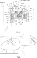
- FIG 1 There figure 1 represents an epicyclic gear train 10 making it possible to obtain a significant rotation speed reduction ratio between an input shaft and an output shaft.
- Such an epicyclic gear train 10 may be arranged in a power transmission box 6 also comprising a lubrication system 50 intended to lubricate and/or cool the rotating elements of the power transmission box 6 using a lubricating liquid such as oil for example.
- the power transmission box 6 thus constitutes a lubricated mechanical system.
- Such an epicyclic gear train 10 may be arranged in a power transmission box 6 of a rotorcraft-type rotary wing aircraft 1 shown in the figure 2 .
- This aircraft 1 may comprise a fuselage 2, a main rotor 3 participating at least partially in the lift of the aircraft 1 and possibly an auxiliary rotor 4 arranged at the end of a tail boom 5.
- the power transmission box 6 is driven in rotation by a power plant 7 provided with at least one motor and drives in rotation the main rotor 3 as well as possibly the auxiliary rotor 4.
- the power transmission box 6 comprises on the one hand, at least one input shaft 62 connected to the power plant 7 and on the other hand, an output shaft 63 connected to the main rotor 3.
- An output shaft (not shown) of the power transmission box 6 can also be connected to the auxiliary rotor 4.
- Such an epicyclic gear train 10 can alternatively be arranged in other lubricated mechanical systems.
- the epicyclic gear train 10 comprises an 11-toothed planetary wheel, a 12-toothed external crown wheel, a planet carrier 20 and several 30-toothed planet wheels carried by the planet carrier 20.
- the section plan of the figure 1 passes through a first axis of rotation AXROT1 of the planet carrier 20 and through a second axis of rotation AXROT2 of a planet wheel 30, the first axis of rotation AXROT1 and the second axis of rotation AXROT2 being parallel.
- the planet carrier 20 may for example be integral with the output shaft 63 and the planetary wheel 11 may be integral with the input shaft 62 or else be integral with an intermediate shaft connected to the input shaft 62 by pinions and gears.
- the external crown 12 is according to this example fixed relative to the power transmission box 6 and integral with a frame 61 of the power transmission box 6.
- the planet carrier 20 comprises a support 21 and several crank pins 22 carried by the support 21.
- the planet carrier 20 is guided in rotation relative to the frame 61 around the first axis of rotation AXROT1 by a main guide device 25.
- Each planet wheel 30 is arranged at least partially around a crank pin 22, an axis of revolution AXM of each crank pin 22 being merged with the second axis of rotation AXROT2.
- Each planet wheel 30 is guided in rotation about the second axis of rotation AXROT2 by a guide device 35.
- the planet wheel 11 is guided in rotation relative to the frame 61 by another guide device 18.
- Each guide device 18, 25, 35 may comprise a plain bearing or one or more bearings with rolling elements such as ball bearings, roller bearings or needle bearings for example.
- the planetary wheel 11 and the planet carrier 20 are arranged, according to this example, to be mobile in rotation around the first axis of rotation. AXROT1.
- the planetary wheel 11, the external ring gear 12 and the planet carrier 20 are coaxial along the first axis of rotation AXROT1.
- Each planetary wheel 30 comprises teeth cooperating with teeth of the external ring gear 12 and teeth of the planetary wheel 11.
- the first axis of rotation AXROT1 can be oriented substantially vertically in a terrestrial reference frame, namely parallel to the direction Z of the terrestrial gravity.
- the lubrication system 50 has the particular function of lubricating the epicyclic gear train 10.
- the lubrication system 50 lubricates the guide devices 35 by injecting a first flow 51 of the lubrication liquid and the main guide device 25 by injecting a second flow 52 of the lubrication liquid.
- the epicyclic gear train 10 also comprises collectors 40 according to the invention, a collector 40 being arranged in each crank pin 22.
- the collector 40 comprises a hollow body 41 provided with an inlet orifice 44 and an outlet orifice 45.
- the collector 40 comprises a barrier 43 provided with a shoulder 42 and a deflector 47.
- the deflector 47 is located on a side opposite the outlet orifice 45 relative to a support plane 31, and is arranged at least locally projecting from the body 41 radially with respect to the geometric axis AX while moving away from this geometric axis AX.
- the barrier 43 delimits a deflection space 431 located between the deflector 47 and the support plane 31.
- the hollow body 41 extends around a geometric axis AX which can be confused with the axis of revolution AXM of the crank pin 22 and/or with the second axis of rotation AXROT2 in use.
- the body 41 hollow may for example be cylindrical and the interior space of the hollow body 41 may also be cylindrical.
- the inlet orifice 44 is intended to receive the first flow 51 of the lubricating liquid coming for example from a first projection point 56 as shown in the figure 2 .
- the first flow 51 can also be directed by gravity towards the inlet orifice 44 of the collector 40.
- the first flow 51 of the lubricating liquid can enter the collector 40 and be directed, for example by the effect of the Earth's gravity and/or a centrifugal force generated by the rotation of the crank pin 22 about the first axis of rotation AXROT1, via the outlet orifice 45 and one or more radial orifices 28 present in the crank pin 22 towards the guide device 35 linked to the crank pin 22. Then, the lubricating liquid flows, after passing through the guide device 35, towards for example a reservoir, in the form of a first return flow 58.
- the deflector 47 projects radially from the body 41 and the shoulder 42 away from the geometric axis AX.
- the deflector 47 is, according to this example, connected to the shoulder 42.
- the deflector 47 has an outside diameter greater than the outside diameter of the shoulder 42 which is itself greater than the outside diameter of the body 41.
- the deflection space 431 of this collector 40 is then closed parallel to the geometric axis AX by the deflector 47 and the external face of the support 21 and/or the external face of the crank pin 22 present in the support plane 31, and radially by the shoulder 42.
- This deflection space 431 is open radially towards the outside, moving away from the geometric axis AX.
- This deflection space 431 thus receives the second flow 52 of the lubricating liquid, this second flow 52 having passed through, for example, the main guide device 25 after having been distributed by a second projection point 57.
- the first flow 51 and the second flow 52 of the lubricating liquid are in fact distinct.
- the barrier 43 then makes it possible to deflect this second flow 52, preventing this second flow 52 from entering the hollow body 41.
- the lubricating liquid can then flow towards, for example, a reservoir in the form of a second return flow, without having entered the crank pin 22 or having passed through the guide device 35.
- the guide device 35 has thus been lubricated only by the first flow 51 which is clean because it comes directly from the first projection point 56.
- the second flow 52 which could possibly have been polluted by foreign particles, for example metallic particles, when passing through the main guide device 25 is thus evacuated without the risk of passing through another guide device for example.
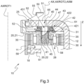
- FIG 3 There figure 3 represents another example of an epicyclic gear train 10 capable of equipping a power transmission box 6.
- the first flow 51 and the second flow 52 of the lubricating liquid can be distributed by the same projection device 55 of the lubrication system 50.
- the projection device 55 is positioned above of the frame 61 to be able to direct the second flow 52 of the lubricating liquid towards the main guide device 25.
- the term “above” is understood, as are the terms “under” and “below”, in relation to the first axis of rotation AXROT1 of the epicyclic gear train 10 oriented from the main guidance device 25 towards the other guidance device 18.
- This first axis of rotation AXROT1 may be for example substantially parallel to the direction Z of Earth's gravity when the aircraft 1 is normally landed on horizontal ground on its landing gear.
- the term “vertical” is understood according to this first axis of rotation AXROT1, namely substantially parallel to the direction Z of Earth's gravity when this aircraft 1 is normally landed on the ground.
- the terms “upper” and “lower” are also understood in relation to this first axis of rotation AXROT1 oriented from the main guidance device 25 towards the other guidance device 18.
- One or more conduits 65 pass through the frame 61 substantially vertically between the projection device 55 and each crank pin 22 in order to direct the first flow 51 towards a collector 40 during rotation of the planet carrier 20.
- the first flow 51 of the lubricating liquid can thus enter the hollow body 41 of the collector 40 via the inlet orifice 44 and accumulate there to then be directed via the outlet orifice 45 and one or more radial orifices 28 present in the crank pin 22 towards the guide device 35 linked to the crank pin 22. Then, the lubricating liquid flows, after having passed through the guide device 35, towards for example a reservoir, in the form of a first return flow 58.
- the deflector 47 of the collector 40 projects radially from the body 41, but has the same diameter as the shoulder. 42.
- the body 41 extends beyond and above the shoulder 42 along the geometric axis AX, up to the deflector 47.
- the deflector 47 is, in this example, connected to the body 41.
- the barrier 43 thus comprises a groove delimited by the deflector 47 and the shoulder 42, the bottom of this groove being formed by the body 41.
- the deflection space 431 of this collector 40 is then closed parallel to the geometric axis AX on the one hand by the deflector 47 and on the other hand by an upper face 422 of the shoulder 42.
- This deflection space 431 is closed radially by the part of the body 41 extending above the shoulder 42, outside the crank pin 22 and is open radially towards the outside moving away from the geometric axis AX.
- the deflection space 431 receives the second flow 52 of the lubricating liquid and the deflector 47 prevents this second flow 52 from entering the hollow body 41.
- the barrier 43 again allows this second flow 52 to be deflected until the lubricating liquid flows towards, for example, a reservoir in the form of a second return flow, without having entered the crank pin 22 or having passed through the guide device 35.
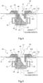
- FIG 4 Another example of collector 40 is shown in the figure 4 . Only the collector 44, the crank pin 22 and the guide device 35 are shown in the figure 4 and the following figures for the sake of simplification of these figures.
- the deflector 47 projects radially from the body 41 and the shoulder 42.
- the deflector 47 is, according to this example, connected to the shoulder 42.
- the deflector 47 is inclined relative to the support plane 31.
- the deflector is thus non-parallel to the support plane 31, and forms with the support plane 31 a deflection angle for example between 15° and 45°.
- the deflector 47 can be inclined relative to the support plane 31, independently other characteristics of the collector 40.
- the deflector 47 can in particular be inclined relative to the support plane 31 on the examples of collectors 40 previously described.
- the deflection space 431 of this collector 40 is then closed parallel to the geometric axis AX by the deflector 47 and by the external face of the support 21 and/or the external face of the crank pin 22 present in the support plane 31 as well as radially by the shoulder 42.
- This deflection space 431 is open radially towards the outside, moving away from the geometric axis AX.
- the deflection space 431 receives the second flow 52 of the lubricating liquid and the deflector 47 prevents this second flow 52 from entering the hollow body 41.
- the barrier 43 again allows this second flow 52 to be deflected until it flows towards, for example, a reservoir, without having entered the crank pin 22 or having passed through the guide device 35.
- this collector 40 may comprise inside the hollow body 41 a backflow prevention wall 46 to maintain a volume of the lubricating liquid in the hollow body 41.
- a backflow prevention wall 46 may be arranged on the collector 40, independently of the other characteristics of the collector 40.
- Such a backflow prevention wall 46 may in particular be integrated on the examples of collectors 40 previously described.
- the backflow prevention wall 46 is annular, centered on the geometric axis AX and linked to an inner wall of the body 41. An opening in the center of the backflow prevention wall 46 constitutes the inlet orifice 44 of the collector 40.
- the backflow prevention wall 46 makes it possible to avoid, or at least limit, a backflow of the lubricating liquid under the effect of a centrifugal force generated by the rotation of the planet carrier 20 around the first axis of rotation AXROT1.
- a minimum volume of the liquid lubrication is thus maintained in the hollow body 41 in order to convey a sufficient quantity of lubricating liquid to the guide device 35 via the outlet orifice 45 and the radial orifice(s) 28.
- FIG 5 There figure 5 represents another example of collector 40 for which the deflector 47 projects radially from the body 41 and the shoulder 42.
- the deflector 47 is, according to this example, connected to the body 41.
- the external diameter of the deflector 47 is, in this example, greater than the external diameters of the body 41 and the shoulder 42.
- the deflector 47 is, according to this example, parallel to the support plane 31.
- FIG 6 There figure 6 represents another example of collector 40 for which the deflector 47 projects radially from the body 41 and the shoulder 42.
- the deflector 47 is, according to this example, connected to the body 41.
- the external diameter of the deflector 47 is, in this example, greater than the external diameters of the body 41 and the shoulder 42.
- the deflector 47 is, according to this example, not parallel to the support plane 31 and therefore inclined relative to the support plane 31.
- the body 41 extends beyond and above the shoulder 42 along the geometric axis AX, up to the deflector 47.
- the external surface of the body 41 located outside the crank pin 22 has a diameter greater than the external surface of the body 41 positioned inside the crank pin 22.
- the barrier 43 thus comprises a groove delimited by the deflector 47 and the upper face 422 of the shoulder 42, the bottom of this groove being formed by the body 41.
- the deflection space 431 for these last two examples is then closed parallel to the geometric axis AX on the one hand by the deflector 47 and on the other hand by an upper face 422 of the shoulder 42 and by the external face of the support 21 and/or the external face of the crank pin 22 present in the support plane 31.
- This space of deflection 431 is closed radially by the part of the body 41 extending beyond the shoulder 42 outside the crank pin 22 and is open radially outwards away from the geometric axis AX.
- the deflection space 431 receives the second flow 52 of the lubricating liquid and the deflector 47 prevents this second flow 52 from entering the hollow body 41.
- the barrier 43 again allows this second flow 52 to be deflected until it flows towards, for example, a reservoir, without having entered the crank pin 22 or having passed through the guide device 35.
- the collectors 40 may also comprise a backflow prevention wall 46 connected to an inner wall of the hollow body 41.
- the backflow prevention wall 46 is asymmetrical around the geometric axis AX and the inlet orifice 44 is formed by an opening between the backflow prevention wall 46 and the inner wall of the hollow body 41.
- the backflow prevention wall 46 is positioned relative to the geometric axis AX on the side opposite the direction of arrival of the second flow 52 on the collector 40.
- the collector 40 and the crank pin 22 may comprise an indexing device 66 making it possible to precisely orient the collector 40 in the crank pin 22.
- the indexing device 66 is provided with a pin 67 arranged on the collector 40 and a housing 68 arranged in the crank pin 22.
- a pin 67 may also be arranged on the crank pin 22, the collector 40 comprising a housing 68.
- the backflow prevention wall 46 may be arranged parallel to the support plane 31 as shown in the Figures 4 to 6 .
- the backflow prevention wall 46 may be inclined relative to the support plane 31 and therefore not parallel to the support plane 31.
- the backflow prevention wall 46 can for example be arranged inside the hollow body 41 as shown in the figure 5 .
- the backflow prevention wall 46 may also be arranged at one end of the hollow body 41 as shown in the figure 6 .
- the backflow preventer 46 makes it possible to maintain a minimum volume of lubricating liquid in the collector 40 and the crank pin 22 regardless of the movements of the planet carrier 20.
- the hollow body 41 may comprise, as shown in the figure 6 , deformation openings 60 in the form of slots arranged between the inlet orifice 44 and the outlet orifice 45.
- the collector 40 also comprises at least one fixing support 70 linked to the body 41 and arranged below the body 41.
- Each fixing support 70 makes it possible to fix the collector 40 to the crank pin 22 using at least one fixing device 71, comprising for example a screw 72 and a nut 73.
- the deformation openings 60 are for example arranged perpendicular to the geometric axis AX.
- the collector 40 when fixing the collector 40 with the crank pin 22 by means of the fixing support 70 and at least one fixing device 71, the collector 40 can deform in traction along the geometric axis AX thanks to the presence of the deformation openings 60. Consequently, the bearing face 421 of the shoulder 42 exerts pressure on the external face of the crank pin 22 and/or the external face of the crank pin 22 ensuring sufficient sealing between on the one hand the collector 40 and on the other hand the crank pin 20. or the support 20 so that no foreign particle contained in the second flow 52 penetrates into the crank pin 22, or even so that this second flow 52 does not penetrate into the crank pin 22.
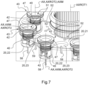
- FIG 7 There figure 7 represents a partial perspective view of a planet carrier 20 carrying collectors 40.
- the first flow 51 and the second flow 52 are shown.
- the first flow 51 is directed towards each collector 40 and then flows, after passing through the guide device 35 (not shown), towards for example a reservoir, in the form of the first return flow 58.
- the second flow 52 circulates on the support 21 of the planet carrier 20 after passing through the main guide device 25 (not shown) to the collector 40.
- the barrier 43 makes it possible to deflect this second flow 52 which can flow through holes 23 of the support 21 towards for example a reservoir in the form of the second return flow 59, without having entered the crank pin 22, nor having passed through the guide device 35 (not shown).
- the deflector 47 of each collector 40 is arranged over the entire periphery of the collector 40 according to the example shown. Consequently, the deflector 47 and the shoulder 42 as well as the barrier 43 are of annular shapes.
- FIG 8 There figure 8 represents a partial perspective view of a planet carrier 20 carrying other collectors 40.
- the deflector 47 covers an angle greater than or equal to 100° around the geometric axis AX, for example equal to 270° around the geometric axis AX according to the example shown.
- the deflector 47 of each collector 40 is centered substantially around a direction connecting the first axis of rotation AXROT1 and the geometric axis AX of this collector 40, for example using an indexing device 60.
- collectors 40 can be integrated into the planet carrier 20 at the level of each crank pin 22, thus forming a single part.
Landscapes
- Engineering & Computer Science (AREA)
- General Engineering & Computer Science (AREA)
- Mechanical Engineering (AREA)
- Aviation & Aerospace Engineering (AREA)
- General Details Of Gearings (AREA)
Description
- La présente invention se situe dans le domaine de la lubrification des systèmes à engrenages, et notamment des boîtes de transmission de puissance d'un aéronef à voilure tournante.
- La présente invention concerne un ensemble. La présente invention concerne également un train épicycloïdal d'engrenages équipé d'un tel ensemble, une boîte de transmission de puissance munie d'un tel train épicycloïdal d'engrenages ainsi qu'un aéronef muni d'une telle boîte de transmission de puissance. Un train épicycloïdal d'engrenages permet de fournir un grand rapport de réduction de la vitesse de rotation entre un arbre d'entrée et un arbre de sortie. Un train épicycloïdal d'engrenages peut être un composant d'un système mécanique tel que par exemple une boîte de vitesse d'un véhicule, notamment d'un aéronef.
- Un train épicycloïdal d'engrenages peut comporter une roue planétaire dentée, une couronne externe dentée, un porte-satellites et plusieurs roues dentées formant des roues-satellites qui sont portées par le porte-satellites. Les dents des roues-satellites sont en prise à la fois avec des dents de la roue planétaire et avec des dents de la couronne externe. Selon l'utilisation du train épicycloïdal d'engrenages, la roue planétaire, le porte-satellites ou la couronne externe sont solidaires de l'arbre d'entrée ou de l'arbre de sortie. Par exemple, la couronne externe est fixe, la roue planétaire étant solidaire de l'arbre d'entrée et le porte-satellites étant solidaire de l'arbre de sortie.
- Le porte-satellites peut comporter un support portant des manetons. Les manetons et le support peuvent former une seule et même pièce ou bien les manetons peuvent être rapportés et fixés rigidement au support.
- Un train épicycloïdal d'engrenages comporte aussi des dispositifs de guidage en rotation des différents éléments tournants, par exemple de la roue planétaire, du porte-satellites et des roues-satellites. Un dispositif de guidage en rotation peut par exemple comporter un palier lisse ou un ou plusieurs paliers à éléments roulants, tels que des roulements à billes, à rouleaux ou encore à aiguilles. Un dispositif de guidage en rotation comporte par exemple une bague intérieure, une bague extérieure et des éléments roulants agencés entre la bague intérieure et la bague extérieure. Par souci de simplification, un tel dispositif de guidage en rotation est désigné plus simplement « dispositif de guidage » par la suite.
- Un train épicycloïdal d'engrenages est généralement lubrifié par un système de lubrification afin de limiter notamment l'échauffement et l'usure des éléments de denture et des dispositifs de guidage et, par suite, d'assurer un bon fonctionnement du train épicycloïdal d'engrenages et de prolonger sa durée de vie. Ce système de lubrification permet notamment d'acheminer un liquide de lubrification vers les zones et les éléments à lubrifier, en particulier les éléments de denture et les dispositifs de guidage. Cette lubrification contribue également à l'évacuation de particules métalliques éventuelles issues de l'usure ou de la dégradation normale d'un élément du train épicycloïdal d'engrenages.
- L'architecture d'un train épicycloïdal d'engrenages et son fonctionnement imposent souvent une lubrification des dispositifs de guidage des roues-satellites, par exemple depuis une bague intérieure par effet centrifuge. Le liquide de lubrification peut par exemple être dirigé dans chaque maneton supportant une roue-satellite puis est mis sous pression sous l'effet de la force centrifuge afin de traverser la bague intérieure pour lubrifier les éléments roulants du dispositif de guidage de cette roue-satellite.
- Toutefois, sous l'effet de vitesses de rotation importantes du porte-satellites et en fonction et de la géométrie du maneton, une partie du liquide de lubrification pourrait être refoulée à l'extérieur du maneton.
- En outre, lorsqu'un dispositif de guidage est situé plus haut que les roues-satellites, par exemple un dispositif de guidage du porte-satellites, un flux de liquide de lubrification peut s'écouler par gravité pour le traverser, et peut éventuellement atteindre ensuite les dispositifs de guidage des roues-satellites. Ce liquide de lubrification est alors susceptible d'être pollué avant d'atteindre les dispositifs de guidage des roues-satellites.
- De façon complémentaire, un autre flux de liquide de lubrification peut être dirigé directement vers les manetons à partir d'asperseurs ou de gicleurs fixes par rapport au bâti du système mécanique. Dans ce cas, un déflecteur peut être intégré au-dessus des dispositifs de guidage des roues-satellites dans le train épicycloïdal d'engrenages pour orienter ce flux de liquide de lubrification vers les dispositifs de guidage des roues-satellites et également limiter la quantité de liquide de lubrification utilisé.
- Un train épicycloïdal peut également comporter une coupelle destinée à alimenter en liquide de lubrification des paliers et des engrenages comme décrit dans le document
US 2018/0258794 . Le liquide de lubrification provient d'un unique moyen d'aspersion fixe. La coupelle est solidaire du porte-satellites et a une forme annulaire autour d'un axe de rotation du porte-satellites. La coupelle comporte une succession circonférentielle de cuvettes séparées par des parois et reliées respectivement à des canalisations de longueurs différentes et agencées radialement. Les canalisations permettent ainsi d'alimenter en liquide de lubrification les paliers des roues-satellites ainsi que les dents des roues-satellites, de la couronne externe ou du planétaire. Le liquide de lubrification peut passer d'une cuvette à une cuvette adjacente lorsque la quantité de liquide de lubrification dépasse la hauteur des parois de la cuvette. - Le document
EP 3964734 , qui relève de l'article 54(3) de la CBE, décrit un dispositif de séparation et de collecte de deux flux d'un liquide de lubrification pour un train épicycloïdal d'engrenages. Un liquide de lubrification est dirigé vers un premier dispositif de guidage en rotation d'un porte-satellites du train épicycloïdal d'engrenages et vers des seconds dispositifs de guidage en rotation de roues-satellites du train épicycloïdal d'engrenages. Le dispositif de séparation et de collecte permet alors d'une part d'acheminer un premier flux du liquide de lubrification vers des seconds dispositifs de guidage du train épicycloïdal d'engrenages et d'autre part d'acheminer un deuxième flux du liquide de lubrification s'écoulant par gravité depuis le premier dispositif de guidage entre deux roues-satellites évitant de la sorte le mélange de ces deux flux. - L'arrière plan technologique de l'invention comporte les documents
DE 10 2012 217307 ,US 2016/0290480 etFR 3098562 - La présente invention a alors pour but de proposer un collecteur de liquide de lubrification pour maneton d'un train épicycloïdal d'engrenages visant notamment à éviter de mélanger deux flux distincts d'un liquide de lubrification afin d'éviter une circulation de liquide de lubrification successivement dans plusieurs dispositifs de guidage en rotation.
- La présente invention a par exemple pour objet un ensemble comportant un collecteur de liquide de lubrification, un dispositif de guidage, un maneton portant ledit dispositif de guidage en rotation et un support portant ledit maneton.
- Le collecteur est configuré pour recevoir un premier flux et un second flux d'un liquide de lubrification, le premier flux et le second flux étant distincts.
- Le collecteur de liquide de lubrification selon l'invention est remarquable en ce qu'il comporte :
- un corps creux autour d'un axe géométrique AX et muni de :
- ∘ un orifice d'entrée configuré pour recevoir le premier flux du liquide de lubrification,
- ∘ un orifice de sortie adapté et configuré pour que le premier flux se dirige vers un dispositif de guidage lié au maneton,
- une barrière configurée pour dévier un second flux du liquide de lubrification, la barrière comportant :
- ∘ un épaulement lié au corps et muni d'une face d'appui, ladite face d'appui étant en appui contre une face externe dudit maneton ou bien contre une face externe dudit support portant ledit maneton, ladite face d'appui s'étendant dans un plan d'appui,
- ∘ un déflecteur situé d'un côté opposé à l'orifice de sortie par rapport au plan d'appui, le déflecteur étant localement en saillie radialement du corps en s'éloignant de l'axe géométrique AX,
- ∘ un espace de déviation du second flux situé entre le déflecteur et le plan d'appui, ledit déflecteur couvrant un angle supérieur ou égal à 100 autour dudit axe géométrique.
- Un premier flux du liquide de lubrification est dirigé par exemple par injection ou pulvérisation vers l'orifice d'entrée du collecteur de liquide par l'intermédiaire d'un dispositif de projection du liquide de lubrification, tel un orifice, un asperseur, un gicleur ou tout moyen équivalent, afin de remplir au moins partiellement le collecteur avec le liquide de lubrification. Le liquide de lubrification est acheminé par exemple par gravité, et éventuellement sous l'effet d'une force centrifuge si le maneton est en rotation, dans une zone inférieure du maneton par l'intermédiaire de l'orifice de sortie. Le maneton peut comporter un ou plusieurs orifices radiaux sur une de ses parois afin que le premier flux du liquide de lubrification soit alors dirigé vers un organe à lubrifier et/ou à refroidir, tel un dispositif de guidage en rotation, positionné par exemple autour du maneton.
- Le premier flux arrivant directement d'un dispositif de projection du liquide de lubrification est propre et non pollué. Un second flux du liquide de lubrification peut par contre avoir été utilisé pour lubrifier et/ou refroidir un autre organe. Ce second flux peut alors avoir été par exemple réchauffé et être de fait moins efficace pour lubrifier et/ou refroidir un organe. Ce second flux peut aussi être pollué.
- La face d'appui de l'épaulement est en appui contre une face externe du maneton ou bien contre une face externe d'un support portant le maneton. La face d'appui de l'épaulement évite ainsi que le second flux du liquide de lubrification, ou au minimum des particules étrangères qu'il comporte, ne pénètrent dans le maneton au niveau de la jonction de cette face d'appui avec une face externe du maneton ou bien une face externe d'un support portant le maneton.
- Le déflecteur est une face de la barrière qui s'étend au moins radialement en saillie à l'extérieur et en périphérie du corps, de sorte à délimiter un espace de déviation avec le plan d'appui et l'épaulement voire une partie du corps. Cet espace de déviation est ouvert radialement sur l'extérieur du collecteur, en s'éloignant de l'axe géométrique AX. Le terme « radialement » s'entend au regard de l'axe géométrique AX. Cet espace de déviation est destiné à accumuler et orienter autour du collecteur le second flux du liquide de lubrification qui est distinct du premier flux.
- La barrière permet ainsi de canaliser et de dévier le second flux et également d'éviter que le second flux ne pénètre dans le corps creux du collecteur. Le second flux du liquide de lubrification peut ainsi être évacué, sans circuler à travers le collecteur selon l'invention, ni par suite à travers l'organe à lubrifier et/ou à refroidir.
- L'ensemble selon l'invention permet ainsi avantageusement d'éviter de mélanger le premier et le second flux de liquide de lubrification et donc de mélanger un flux de liquide de lubrification propre avec un flux possiblement pollué ou réchauffé. L'ensemble selon l'invention permet également d'évacuer le second flux en évitant qu'il soit introduit dans le collecteur.
- L'ensemble selon l'invention peut comporter les caractéristiques qui suivent, prises selon les revendications dépendantes.
- De préférence, le déflecteur peut couvrir un angle supérieur ou égal à 270° autour de l'axe géométrique AX.
- En outre, la barrière dans sa totalité, à savoir le déflecteur et l'épaulement, peut éventuellement couvrir un tel angle limité autour de l'axe géométrique AX en périphérie du corps.
- Alternativement, le déflecteur et l'épaulement peuvent couvrir des angles limités différents autour de l'axe géométrique AX en périphérie du corps. Par exemple, l'épaulement couvre un premier angle limité supérieur à un second angle limité couvert par le déflecteur.
- Alternativement, la barrière dans sa totalité, à savoir le déflecteur et l'épaulement, peut couvrir en totalité la périphérie du corps autour de l'axe géométrique AX, à savoir un angle de 360° autour de l'axe géométrique AX. La barrière est ainsi de forme annulaire. En conséquence, le déflecteur et l'épaulement sont également de formes annulaires.
- Selon un autre exemple, le plan d'appui est perpendiculaire à l'axe géométrique AX. L'axe géométrique AX est par exemple un axe de symétrie d'au moins une partie du corps creux lorsqu'il est par exemple au moins en partie cylindrique à base circulaire.
- Selon un autre exemple, le déflecteur peut être parallèle au plan d'appui. Le déflecteur comporte notamment une face en regard du plan d'appui et parallèle à ce plan d'appui.
- Alternativement, le déflecteur peut être non parallèle au plan d'appui et comporter ainsi une face inclinée par rapport à la face d'appui. De préférence, l'angle de déflection entre le plan d'appui et le déflecteur peut être compris entre 15° et 45° afin de limiter l'encombrement de la barrière.
- Cependant, cet angle de déflection peut être supérieur à 45°, voire être supérieur ou égal à 90° lorsque l'espace disponible au-dessus du maneton le permet.
- Selon un autre exemple, l'espace de déviation peut être limité selon une direction parallèle à l'axe géométrique AX d'une part par le déflecteur et d'autre part par le plan d'appui et radialement, par rapport à l'axe géométrique AX, par l'épaulement en direction de l'axe géométrique AX. L'espace de déviation est ouvert radialement vers l'extérieur en s'éloignant de l'axe géométrique AX.
- Alternativement, l'espace de déviation peut être limité selon une direction parallèle à l'axe géométrique AX d'une part par le déflecteur et d'autre part par le plan d'appui et radialement, par rapport à l'axe géométrique AX, par l'épaulement et le corps en direction de l'axe géométrique AX. L'espace de déviation est ouvert radialement vers l'extérieur en s'éloignant de l'axe géométrique AX.
- Alternativement, l'espace de déviation peut être limité selon une direction parallèle à l'axe géométrique AX d'une part par le déflecteur et d'autre part par l'épaulement et/ou le plan d'appui et radialement, par rapport à l'axe géométrique AX, par le corps en direction de l'axe géométrique AX. L'espace de déviation est ouvert radialement vers l'extérieur en s'éloignant de l'axe géométrique AX.
- Selon un autre exemple, le collecteur peut comporter une paroi anti-refoulement pour maintenir un volume de liquide de lubrification dans le corps creux. La paroi anti-refoulement permet de bloquer une partie du liquide de lubrification et de maintenir ainsi un volume minimum de liquide de lubrification dans le corps creux en fonction des mouvements et/ou des accélérations subis par le collecteur. En conséquence, l'organe à lubrifier et/ou à refroidir peut être alimenté constamment en liquide de lubrification.
- La paroi anti-refoulement est liée au corps creux. La paroi anti-refoulement peut par exemple être agencée à l'intérieur du corps creux et liée à une paroi intérieure du corps creux.
- La paroi anti-refoulement peut être de forme annulaire et centrée sur l'axe géométrique AX. L'orifice d'entrée est alors formé par une ouverture au centre de la paroi anti-refoulement.
- La paroi anti-refoulement peut être liée à une paroi intérieure du corps creux et l'orifice d'entrée est alors formé par une ouverture entre la paroi anti-refoulement et une paroi du corps creux. La paroi anti-refoulement est ainsi asymétrique autour de l'axe géométrique AX. La position du collecteur peut alors être indexée par rapport au maneton pour maintenir efficacement le volume minimum de liquide de lubrification dans le corps creux en fonction des mouvements et/ou des accélérations subis par le collecteur. Le collecteur et le maneton peuvent comporter un dispositif d'indexage, tel que précédemment évoqué, permettant d'orienter précisément le collecteur dans le maneton.
- Selon un autre exemple, le corps creux peut comporter des ouvertures de déformation en forme de fentes agencées sur une paroi du corps creux entre l'orifice d'entrée et l'orifice de sortie, le collecteur comportant au moins un support de fixation configuré pour fixer le collecteur au maneton à l'aide d'au moins un dispositif de fixation. Ledit au moins un support de fixation est lié au corps creux. Le collecteur est dimensionné de sorte qu'en fixant le collecteur au maneton à l'aide d'au moins un support de fixation et d'au moins un dispositif de fixation, le corps creux se déforme et s'allonge grâce aux ouvertures de déformation afin que la face d'appui de l'épaulement de la barrière exerce une pression sur une face externe du maneton ou une face externe d'un support portant le maneton. Cette pression permet d'assurer une étanchéité entre d'une part le collecteur, et en particulier sa barrière, et d'autre part le maneton ou le support portant le maneton afin d'empêcher au minimum que des particules étrangères contenues dans le second flux du liquide de lubrification pénètrent dans le maneton, voire que ce second flux pénètre dans le maneton.
- Les ouvertures de déformation doivent être non parallèles à l'axe géométrique AX pour contribuer à la déformation en traction selon l'axe géométrique AX du corps creux. Les fentes peuvent par exemple être agencées dans des plans perpendiculaires à l'axe géométrique AX.
- La présente invention vise également un train épicycloïdal d'engrenages comportant un porte-satellites et plusieurs roues-satellites dentées portées par le porte-satellites, le porte-satellites comportant ledit support et plusieurs manetons portés par le support,
chaque roue-satellite ayant des dents agencées autour d'un maneton, le train épicycloïdal d'engrenages comportant des dispositifs de guidage en rotation des roues-satellites par rapport aux manetons. Les manetons et le support peuvent former une seule et même pièce. - La face d'appui de chaque collecteur peut être en appui sur une face externe du support ou une face externe d'un maneton parmi les manetons.
- L'axe géométrique AX de chaque collecteur peut être confondu avec un axe de révolution AXM du maneton dans lequel le collecteur est agencé.
- En outre, lorsque le déflecteur de chaque collecteur couvre un angle strictement inférieur à 360° autour de l'axe géométrique AX, chaque collecteur peut être agencé dans un maneton de sorte que le déflecteur couvre un angle supérieur ou égal à 50° de part et d'autre d'une ligne reliant l'axe géométrique AX et un premier axe de rotation AXROT1 du porte-satellite.
- La présente invention vise aussi une boîte de transmission de puissance comportant un tel train épicycloïdal d'engrenages et un système de lubrification.
- La boîte de transmission de puissance peut comporter un bâti et un dispositif de guidage principal agencé entre le bâti et le porte-satellites, le bâti comportant un conduit à travers lequel est acheminé le premier flux du liquide de lubrification en direction des collecteurs lors d'une rotation du porte-satellites.
- Le système de lubrification distribue le premier flux et un second flux de liquide de lubrification sur le train épicycloïdal d'engrenages, le premier flux étant dirigé vers les collecteurs via le conduit et le second flux étant dirigé vers le dispositif de guidage principal.
- La présente invention vise enfin un aéronef comportant une boîte de transmission de puissance telle que précédemment décrite. L'invention et ses avantages apparaîtront avec plus de détails dans le cadre de la description qui suit avec des exemples donnés à titre illustratif en référence aux figures annexées qui représentent :
- la
figure 1 , une vue en coupe d'un train épicycloïdal d'engrenages muni d'un ensemble selon l'invention, - la
figure 2 , une vue schématique de côté d'un aéronef, - la
figure 3 , une vue en coupe d'un train épicycloïdal d'engrenages muni d'un ensemble selon l'invention, - les
figures 4 à 6 , des vues en coupe d'un maneton et d'un collecteur faisant partie de l'ensemble selon l'invention, et - les
figures 7 à 8 , deux vues en perspective d'un porte-satellites portant des collecteurs. - Les éléments présents dans plusieurs figures distinctes sont affectés d'une seule et même référence.
- [
Fig 1 ] Lafigure 1 représente un train épicycloïdal d'engrenages 10 permettant d'obtenir un rapport important de réduction de vitesse de rotation entre un arbre d'entrée et un arbre de sortie. - Un tel train épicycloïdal d'engrenages 10 peut être agencé dans une boîte de transmission de puissance 6 comportant aussi un système de lubrification 50 destiné à lubrifier et/ou à refroidir les éléments tournants de la boîte de transmission de puissance 6 en utilisant un liquide de lubrification tel que de l'huile par exemple. La boîte de transmission de puissance 6 constitue ainsi un système mécanique lubrifié.
- [
Fig 2 ] Un tel train épicycloïdal d'engrenages 10 peut être agencé dans une boîte de transmission de puissance 6 d'un aéronef 1 à voilure tournante de type giravion représenté sur lafigure 2 . Cet aéronef 1 peut comporter un fuselage 2, un rotor principal 3 participant au moins partiellement à la sustentation de l'aéronef 1 et éventuellement un rotor auxiliaire 4 agencé à l'extrémité d'une poutre de queue 5. La boîte de transmission de puissance 6 est entraînée en rotation par une installation motrice 7 munie d'au moins un moteur et entraîne en rotation le rotor principal 3 ainsi qu'éventuellement le rotor auxiliaire 4. - Par exemple et dans ce cadre, la boîte de transmission de puissance 6 comporte d'une part, au moins un arbre d'entrée 62 relié à l'installation motrice 7 et d'autre part, un arbre de sortie 63 relié au rotor principal 3. Un arbre de sortie (non représenté) de la boîte de transmission de puissance 6 peut aussi être relié au rotor auxiliaire 4.
- Un tel train épicycloïdal d'engrenages 10 peut alternativement être agencé dans d'autres systèmes mécaniques lubrifiés.
- Le train épicycloïdal d'engrenages 10 comporte une roue planétaire 11 dentée, une couronne externe 12 dentée, un porte-satellites 20 et plusieurs roues-satellites 30 dentées portées par le porte-satellites 20.
- Le plan de coupe de la
figure 1 passe par un premier axe de rotation AXROT1 du porte-satellites 20 et par un second axe de rotation AXROT2 d'une roue-satellite 30, le premier axe de rotation AXROT1 et le second axe de rotation AXROT2 étant parallèles. - Le porte-satellites 20 peut être par exemple solidaire de l'arbre de sortie 63 et la roue planétaire 11 peut être solidaire de l'arbre d'entrée 62 ou bien être solidaire d'un arbre intermédiaire relié à l'arbre d'entrée 62 par des pignons et des engrenages. La couronne externe 12 est selon cet exemple fixe par rapport à la boîte de transmission de puissance 6 et solidaire d'un bâti 61 de la boîte de transmission de puissance 6.
- Le porte-satellites 20 comporte un support 21 et plusieurs manetons 22 portés par le support 21. Le porte-satellites 20 est guidé en rotation par rapport au bâti 61 autour du premier axe de rotation AXROT1 par un dispositif de guidage principal 25. Chaque roue-satellite 30 est agencée au moins partiellement autour d'un maneton 22, un axe de révolution AXM de chaque maneton 22 étant confondu avec le second axe de rotation AXROT2. Chaque roue-satellite 30 est guidée en rotation autour du second axe de rotation AXROT2 par un dispositif de guidage 35. La roue planétaire 11 est guidée en rotation par rapport au bâti 61 par un autre dispositif de guidage 18. Chaque dispositif de guidage 18, 25, 35 peut comporter un palier lisse ou un ou plusieurs paliers à éléments roulants tels que des roulements à billes, à rouleaux ou encore à aiguilles par exemple.
- La roue planétaire 11 et le porte-satellites 20 sont agencés, selon cet exemple, mobiles en rotation autour du premier axe de rotation AXROT1. De plus, la roue planétaire 11, la couronne externe 12 et le porte-satellites 20 sont coaxiaux selon le premier axe de rotation AXROT1. Chaque roue-satellite 30 comporte des dents coopérant avec des dents de la couronne externe 12 et des dents de la roue planétaire 11. Lorsque l'aéronef 1 est posé sur un sol plat, le premier axe de rotation AXROT1 peut être orienté sensiblement verticalement dans un repère terrestre, à savoir parallèlement à la direction Z de la gravité terrestre.
- Quelle que soit l'implantation du train épicycloïdal d'engrenages 10, le système de lubrification 50 a notamment pour fonction de lubrifier le train épicycloïdal d'engrenages 10. En particulier, le système de lubrification 50 lubrifie les dispositifs de guidage 35 en injectant un premier flux 51 du liquide de lubrification et le dispositif de guidage principal 25 en injectant un second flux 52 du liquide de lubrification.
- Le train épicycloïdal d'engrenages 10 comporte également des collecteurs 40 selon l'invention, un collecteur 40 étant agencé dans chaque maneton 22.
- Quelle que soit la nature du système mécanique muni d'un tel collecteur 40, le collecteur 40 comporte un corps 41 creux muni d'un orifice d'entrée 44 et d'un orifice de sortie 45. Le collecteur 40 comprend une barrière 43 munie d'un épaulement 42 et d'un déflecteur 47. Le déflecteur 47 est situé d'un côté opposé à l'orifice de sortie 45 par rapport à un plan d'appui 31, et est agencé au moins localement en saillie du corps 41 radialement au regard de l'axe géométrique AX en s'éloignant de cet axe géométrique AX. La barrière 43 délimite un espace de déviation 431 situé entre le déflecteur 47 et le plan d'appui 31.
- Le corps 41 creux s'étend autour d'un axe géométrique AX qui peut être confondu avec l'axe de révolution AXM du maneton 22 et/ou avec le second axe de rotation AXROT2 en utilisation. Le corps 41 creux peut par exemple être cylindrique et l'espace intérieur du corps 41 creux peut également être cylindrique.
- L'orifice d'entrée 44 est destiné à recevoir le premier flux 51 du liquide de lubrification provenant par exemple d'un premier point de projection 56 comme représenté sur la
figure 2 . Le premier flux 51 peut également être dirigé par gravité vers l'orifice d'entrée 44 du collecteur 40. - Le premier flux 51 du liquide de lubrification peut pénétrer dans le collecteur 40 et être dirigé, par exemple par l'effet de la gravité terrestre et/ou d'une force centrifuge générée par la rotation du maneton 22 autour du premier axe de rotation AXROT1, via l'orifice de sortie 45 et un ou plusieurs orifices radiaux 28 présents dans le maneton 22 vers le dispositif de guidage 35 lié au maneton 22. Ensuite, le liquide de lubrification s'écoule, après avoir traversé le dispositif de guidage 35, vers par exemple un réservoir, sous la forme d'un premier flux de retour 58.
- Par ailleurs, l'épaulement 42 est lié au corps 41 et est muni d'une face d'appui 421. Cette face d'appui 421 est en appui sur une face externe du support 21 ou une face externe du maneton 22. Cette face d'appui 421 s'étend dans un plan d'appui 31 qui est par exemple perpendiculaire à l'axe géométrique AX. Selon le train épicycloïdal d'engrenages 10 représenté sur la
figure 1 , les manetons 22 et le support 21 forment une seule et même pièce. Alternativement, les manetons 22 et le support 21 peuvent être des pièces distinctes. - Selon l'exemple de collecteur 40 représenté sur la
figure 1 , le déflecteur 47 est en saillie radialement du corps 41 et de l'épaulement 42 en s'éloignant de l'axe géométrique AX. Le déflecteur 47 est selon cet exemple lié à l'épaulement 42. Lorsque le corps 41, le déflecteur 47 et de l'épaulement 42 sont de forme cylindrique à base circulaire, le déflecteur 47 a un diamètre extérieur supérieur au diamètre extérieur de l'épaulement 42 qui est lui-même supérieur au diamètre extérieur du corps 41. - L'espace de déviation 431 de ce collecteur 40 est alors fermé parallèlement à l'axe géométrique AX par le déflecteur 47 et la face externe du support 21 et/ou la face externe du maneton 22 présente dans le plan d'appui 31, et radialement par l'épaulement 42. Cet espace de déviation 431 est ouvert radialement vers l'extérieur en s'éloignant de l'axe géométrique AX.
- Cet espace de déviation 431 reçoit ainsi le second flux 52 du liquide de lubrification, ce second flux 52 ayant traversé par exemple le dispositif de guidage principal 25 après avoir été distribué par un second point de projection 57. Le premier flux 51 et le second flux 52 du liquide de lubrification sont de fait distincts. La barrière 43 permet alors de dévier ce second flux 52, évitant que ce second flux 52 ne rentre dans le corps 41 creux. Le liquide de lubrification peut alors s'écouler vers par exemple un réservoir sous la forme d'un second flux de retour, sans être rentré dans le maneton 22, ni avoir traversé le dispositif de guidage 35.
- Le dispositif de guidage 35 a ainsi été lubrifié uniquement par le premier flux 51 qui est propre car provenant directement du premier point de projection 56. Le second flux 52 qui a pu éventuellement être pollué par des particules étrangères, par exemple métalliques en traversant le dispositif de guidage principal 25 est ainsi évacué sans risque de traverser un autre dispositif de guidage par exemple.
- [
Fig 3 ] Lafigure 3 représente un autre exemple d'un train épicycloïdal d'engrenages 10 susceptible d'équiper une boîte de transmission de puissance 6. Selon cet exemple, le premier flux 51 et le second flux 52 du liquide de lubrification peuvent être distribués par un même dispositif de projection 55 du système de lubrification 50. Dans ce cas, le dispositif de projection 55 est positionné au-dessus du bâti 61 pour pouvoir diriger le second flux 52 du liquide de lubrification en direction du dispositif de guidage principal 25. - Le terme « au-dessus » s'entend, de même que les termes « sous » et « en dessous », par rapport au premier axe de rotation AXROT1 du train épicycloïdal d'engrenages 10 orienté du dispositif de guidage principal 25 vers l'autre dispositif de guidage 18. Ce premier axe de rotation AXROT1 peut être par exemple sensiblement parallèle à la direction Z de la gravité terrestre lorsque l'aéronef 1 est posé normalement sur un sol horizontal sur ses trains d'atterrissage. De même, le terme « verticale » s'entend selon ce premier axe de rotation AXROT1, à savoir sensiblement parallèlement à la direction Z de la gravité terrestre lorsque cet aéronef 1 est posé normalement au sol. En outre, les termes « supérieur » et « inférieur » s'entendent également par rapport à ce premier axe de rotation AXROT1 orienté du dispositif de guidage principal 25 vers l'autre dispositif de guidage 18.
- Un ou plusieurs conduits 65 traversent le bâti 61 sensiblement verticalement entre le dispositif de projection 55 et chaque maneton 22 afin de diriger le premier flux 51 vers un collecteur 40 lors de la rotation du porte-satellites 20.
- Le premier flux 51 du liquide de lubrification peut ainsi entrer dans le corps 41 creux du collecteur 40 par l'orifice d'entrée 44 et s'y accumuler pour être ensuite dirigé via l'orifice de sortie 45 et un ou plusieurs orifices radiaux 28 présents dans le maneton 22 vers le dispositif de guidage 35 lié au maneton 22. Ensuite, le liquide de lubrification s'écoule, après avoir traversé le dispositif de guidage 35, vers par exemple un réservoir, sous la forme d'un premier flux de retour 58.
- Selon cet exemple, le déflecteur 47 du collecteur 40 est en saillie radialement du corps 41, mais a un même diamètre que l'épaulement 42. Le corps 41 se prolonge au-delà et au-dessus de l'épaulement 42 selon l'axe géométrique AX, jusqu'au déflecteur 47. Le déflecteur 47 est selon cet exemple lié au corps 41. La barrière 43 comporte ainsi une gorge délimitée par le déflecteur 47 et l'épaulement 42, le fond de cette gorge étant formé par le corps 41.
- L'espace de déviation 431 de ce collecteur 40 est alors fermé parallèlement à l'axe géométrique AX d'une part par le déflecteur 47 et d'autre part par une face supérieure 422 de l'épaulement 42. Cet espace de déviation 431 est fermé radialement par la partie du corps 41 s'étendant au-dessus de l'épaulement 42, à l'extérieur du maneton 22 et est ouvert radialement vers l'extérieur en s'éloignant de l'axe géométrique AX.
- Comme précédemment, l'espace de déviation 431 reçoit le second flux 52 du liquide de lubrification et le déflecteur 47 empêche que ce second flux 52 ne rentre dans le corps 41 creux. La barrière 43 permet de nouveau de dévier ce second flux 52 jusqu'à ce que le liquide de lubrification s'écoule vers par exemple un réservoir sous la forme d'un second flux de retour, sans être rentré dans le maneton 22, ni avoir traversé le dispositif de guidage 35.
- [
Fig 4 ] Un autre exemple de collecteur 40 est représenté sur lafigure 4 . Seuls, le collecteur 44, le maneton 22 et le dispositif de guidage 35 sont représentés sur lafigure 4 et les figures suivantes par souci de simplification de ces figures. - Selon cet exemple de collecteur 40, le déflecteur 47 est en saillie radialement du corps 41 et de l'épaulement 42. Le déflecteur 47 est selon cet exemple lié à l'épaulement 42. Le déflecteur 47 est incliné par rapport au plan d'appui 31. Le déflecteur est ainsi non parallèle au plan d'appui 31, et forme avec le plan d'appui 31 un angle de déflection par exemple compris entre 15° et 45°. Le déflecteur 47 peut être incliné par rapport au plan d'appui 31, indépendamment des autres caractéristiques du collecteur 40. Le déflecteur 47 peut notamment être incliné par rapport au plan d'appui 31 sur les exemples de collecteurs 40 précédemment décrits.
- L'espace de déviation 431 de ce collecteur 40 est alors fermé parallèlement à l'axe géométrique AX par le déflecteur 47 et par la face externe du support 21 et/ou la face externe du maneton 22 présente dans le plan d'appui 31 ainsi que radialement par l'épaulement 42. Cet espace de déviation 431 est ouvert radialement vers l'extérieur en s'éloignant de l'axe géométrique AX.
- Comme précédemment, l'espace de déviation 431 reçoit le second flux 52 du liquide de lubrification et le déflecteur 47 empêche que ce second flux 52 ne rentre dans le corps 41 creux. La barrière 43 permet de nouveau de dévier ce second flux 52 jusqu'à ce qu'il s'écoule vers par exemple un réservoir, sans être rentré dans le maneton 22, ni avoir traversé le dispositif de guidage 35.
- De plus, ce collecteur 40 peut comporter à l'intérieur du corps 41 creux une paroi anti-refoulement 46 pour maintenir un volume du liquide de lubrification dans le corps 41 creux. Une paroi anti-refoulement 46 peut être agencée sur le collecteur 40, indépendamment des autres caractéristiques du collecteur 40. Une telle paroi anti-refoulement 46 peut notamment être intégrée sur les exemples de collecteurs 40 précédemment décrits. Selon cet exemple, la paroi anti-refoulement 46 est annulaire, centrée sur l'axe géométrique AX et liée à une paroi intérieure du corps 41. Une ouverture au centre de la paroi anti-refoulement 46 constitue l'orifice d'entrée 44 du collecteur 40.
- La paroi anti-refoulement 46 permet d'éviter, ou au minimum de limiter, un refoulement du liquide de lubrification sous l'effet d'une force centrifuge générée par la rotation du porte-satellites 20 autour du premier axe de rotation AXROT1. Un volume minimum du liquide de lubrification est ainsi maintenu dans le corps 41 creux afin d'acheminer une quantité de liquide de lubrification suffisante vers le dispositif de guidage 35 via l'orifice de sortie 45 et le ou les orifices radiaux 28.
- [
Fig 5 ] Lafigure 5 représente un autre exemple de collecteur 40 pour lequel le déflecteur 47 est en saillie radialement du corps 41 et de l'épaulement 42. Le déflecteur 47 est selon cet exemple lié au corps 41. Le diamètre extérieur du déflecteur 47 est dans cet exemple supérieur aux diamètres extérieurs du corps 41 et l'épaulement 42. Le déflecteur 47 est selon cet exemple parallèle au plan d'appui 31. - [
Fig 6 ] Lafigure 6 représente un autre exemple de collecteur 40 pour lequel le déflecteur 47 est en saillie radialement du corps 41 et de l'épaulement 42. Le déflecteur 47 est selon cet exemple lié au corps 41. Le diamètre extérieur du déflecteur 47 est dans cet exemple supérieur aux diamètres extérieurs du corps 41 et de l'épaulement 42. Le déflecteur 47 est selon cet exemple non parallèle au plan d'appui 31 et donc incliné par rapport au plan d'appui 31. - De façon commune à ces deux exemples des
figures 5 et6 , le corps 41 se prolonge au-delà et au dessus de l'épaulement 42 selon l'axe géométrique AX, jusqu'au déflecteur 47. La surface externe du corps 41 située à l'extérieur du maneton 22 a un diamètre supérieur à la surface externe du corps 41 positionnée à l'intérieur du maneton 22. La barrière 43 comporte ainsi une gorge délimitée par le déflecteur 47 et la face supérieure 422 de l'épaulement 42, le fond de cette gorge étant formé par le corps 41. - L'espace de déviation 431 pour ces deux derniers exemples est alors fermé parallèlement à l'axe géométrique AX d'une part par le déflecteur 47 et d'autre part par une face supérieure 422 de l'épaulement 42 et par la face externe du support 21 et/ou la face externe du maneton 22 présente dans le plan d'appui 31. Cet espace de déviation 431 est fermé radialement par la partie du corps 41 s'étendant au-delà de l'épaulement 42 à l'extérieur du maneton 22 et est ouvert radialement vers l'extérieur en s'éloignant de l'axe géométrique AX.
- De façon commune à ces deux derniers exemples de collecteur 40 et comme précédemment, l'espace de déviation 431 reçoit le second flux 52 du liquide de lubrification et le déflecteur 47 empêche que ce second flux 52 ne rentre dans le corps 41 creux. La barrière 43 permet de nouveau de dévier ce second flux 52 jusqu'à ce qu'il s'écoule vers par exemple un réservoir, sans être rentré dans le maneton 22, ni avoir traversé le dispositif de guidage 35.
- Les collecteurs 40 selon ces deux derniers exemples peuvent aussi comporter une paroi anti-refoulement 46 liée à une paroi intérieure du corps 41 creux. La paroi anti-refoulement 46 est asymétrique autour de l'axe géométrique AX et l'orifice d'entrée 44 est formé par une ouverture entre la paroi anti-refoulement 46 et la paroi intérieure du corps 41 creux. La paroi anti-refoulement 46 est positionnée par rapport à l'axe géométrique AX du côté opposé à la direction d'arrivée du second flux 52 sur le collecteur 40.
- La position du collecteur 40 doit alors être indexée par rapport au maneton 22 pour maintenir la position de la paroi anti-refoulement 46 opposée à la direction d'arrivée du second flux 52 sur le collecteur 40 par rapport à l'axe géométrique AX. Dans ce but, le collecteur 40 et le maneton 22 peuvent comporter un dispositif d'indexage 66 permettant d'orienter précisément le collecteur 40 dans le maneton 22. Le dispositif d'indexage 66 est muni d'un pion 67 agencé sur le collecteur 40 et d'un logement 68 agencé dans le maneton 22. Alternativement, un pion 67 peut aussi être agencé sur le maneton 22, le collecteur 40 comportant un logement 68.
- Indépendamment des autres caractéristiques du collecteur 40, la paroi anti-refoulement 46 peut être agencée parallèlement au plan d'appui 31 comme représentée sur les
figures 4 à 6 . Alternativement, la paroi anti-refoulement 46 peut être inclinée par rapport plan d'appui 31 et donc non parallèle au plan d'appui 31. - La paroi anti-refoulement 46 peut par exemple être agencée à l'intérieur du corps 41 creux comme représenté sur la
figure 5 . La paroi anti-refoulement 46 peut aussi être agencée à une extrémité du corps 41 creux comme représenté sur lafigure 6 . - La paroi anti-refoulement 46 permet de maintenir un volume minimum de liquide de lubrification dans le collecteur 40 et le maneton 22 quels que soient les mouvements du porte-satellites 20.
- De plus, indépendamment des autres caractéristiques du collecteur 40, le corps 41 creux peut comporter, comme représenté sur la
figure 6 , des ouvertures de déformation 60 en forme de fentes agencées entre l'orifice d'entrée 44 et l'orifice de sortie 45. Le collecteur 40 comporte aussi au moins un support de fixation 70 lié au corps 41 et agencé en dessous du corps 41. Chaque support de fixation 70 permet de fixer le collecteur 40 au maneton 22 à l'aide d'au moins un dispositif de fixation 71, comportant par exemple une vis 72 et un écrou 73. Les ouvertures de déformation 60 sont par exemple agencées perpendiculairement à l'axe géométrique AX. - De la sorte, lors de la fixation du collecteur 40 avec le maneton 22 par l'intermédiaire du support de fixation 70 et d'au moins un dispositif de fixation 71, le collecteur 40 peut se déformer en traction selon l'axe géométrique AX grâce à la présence des ouvertures de déformation 60. En conséquence, la face d'appui 421 de l'épaulement 42 exerce une pression sur la face externe du maneton 22 et/ou la face externe du maneton 22 assurant une étanchéité suffisante entre d'une part le collecteur 40 et d'autre le maneton 20 ou le support 20 pour qu'aucune particule étrangère contenue dans le second flux 52 ne pénètre dans le maneton 22, voire que ce second flux 52 ne pénètre pas dans le maneton 22.
- [
Fig 7 ] Lafigure 7 représente une vue partielle en perspective d'un porte-satellites 20 portant des collecteurs 40. Le premier flux 51 et le second flux 52 sont représentés. Le premier flux 51 est dirigé vers chaque collecteur 40 puis s'écoule, après avoir traversé le dispositif de guidage 35 (non représenté), vers par exemple un réservoir, sous la forme du premier flux de retour 58. Le second flux 52 circule sur le support 21 du porte-satellite 20 après avoir traversé le dispositif de guidage principal 25 (non représenté) jusqu'au collecteur 40. La barrière 43 permet de dévier ce second flux 52 qui peut s'écouler au travers de trous 23 du support 21 vers par exemple un réservoir sous la forme du second flux de retour 59, sans être rentré dans le maneton 22, ni avoir traversé le dispositif de guidage 35 (non représenté). Le déflecteur 47 de chaque collecteur 40 est agencé sur la totalité de la périphérie du collecteur 40 selon l'exemple représenté. En conséquence, le déflecteur 47 et l'épaulement 42 ainsi que la barrière 43 sont de formes annulaires. - [
Fig 8 ] Lafigure 8 représente une vue partielle en perspective d'un porte-satellites 20 portant d'autres collecteurs 40. Pour chaque collecteur 40, le déflecteur 47 couvre un angle supérieur ou égal à 100° autour de l'axe géométrique AX, par exemple égal à 270° autour de l'axe géométrique AX selon l'exemple représenté. Le déflecteur 47 de chaque collecteur 40 est centré sensiblement autour d'une direction reliant le premier axe de rotation AXROT1 et l'axe géométrique AX de ce collecteur 40, par exemple à l'aide d'un dispositif d'indexage 60. - Par ailleurs, les collecteurs 40 peuvent être intégrés au porte-satellites 20 au niveau de chaque maneton 22, formant ainsi une unique pièce.
- Naturellement, la présente invention est sujette à de nombreuses variations quant à sa mise en oeuvre. Bien que plusieurs modes de réalisation aient été décrits, on comprend bien qu'il n'est pas concevable d'identifier de manière exhaustive tous les modes possibles. Il est bien sûr envisageable de remplacer un moyen décrit par un moyen équivalent sans sortir du cadre de la présente invention défini par les revendications.
Claims (14)
- Ensemble comportant un collecteur (40) de liquide de lubrification, un dispositif de guidage (35), un maneton (22) portant ledit dispositif de guidage (35) en rotation et un support (21) portant ledit maneton (22), ledit collecteur (40) étant configuré pour recevoir un premier flux (51) et un second flux (52) d'un liquide de lubrification, ledit premier flux (51) et ledit second flux (52) étant distincts,
ledit collecteur (40) comportant :- un corps (41) creux autour d'un axe géométrique (AX) dudit collecteur (40) et muni de :∘ un orifice d'entrée (44) configuré pour recevoir ledit premier flux (51) dudit liquide de lubrification,∘ un orifice de sortie (45) configuré pour diriger ledit premier flux (51) vers ledit dispositif de guidage (35) lié audit maneton (22),- une barrière (43) configurée pour dévier ledit second flux (52) dudit liquide de lubrification, ladite barrière (43) comportant :caractérisé en ce que ledit collecteur (40) comporte un espace de déviation (431) dudit second flux (52) situé entre ledit déflecteur (47) et ledit plan d'appui (31), et ledit déflecteur (47) couvre un angle supérieur ou égal à 100° autour dudit axe géométrique (AX).∘ un épaulement (42) lié audit corps (41) et muni d'une face d'appui (421), ladite face d'appui (421) étant en appui contre une face externe dudit maneton (22) ou bien contre une face externe dudit support (21) portant ledit maneton (22), ladite face d'appui (421) s'étendant dans un plan d'appui (31), et∘ un déflecteur (47) situé d'un côté opposé audit orifice de sortie (45) par rapport audit plan d'appui (31), ledit déflecteur (47) étant localement en saillie radialement dudit corps (41) en s'éloignant dudit axe géométrique (AX), - Ensemble selon la revendication 1,
caractérisé en ce que ledit déflecteur (47) couvre un angle supérieur ou égal à 270° autour dudit axe géométrique (AX). - Ensemble selon l'une quelconque des revendications 1 à 2, caractérisé en ce que ledit plan d'appui (31) est perpendiculaire audit axe géométrique (AX).
- Ensemble selon l'une quelconque des revendications 1 à 3,
caractérisé en ce que ledit déflecteur (47) est parallèle audit plan d'appui (31). - Ensemble selon l'une quelconque des revendications 1 à 3,
caractérisé en ce que ledit déflecteur (47) est incliné par rapport audit plan d'appui (31). - Ensemble selon l'une quelconque des revendications 1 à 5,
caractérisé en ce que ledit espace de déviation (431) est limité selon une direction parallèle audit axe géométrique (AX) d'une part par ledit déflecteur (47) et d'autre part par le plan d'appui (31) et radialement par ledit épaulement (42) en direction dudit axe géométrique (AX), ledit espace de déviation (431) étant ouvert radialement vers l'extérieur en s'éloignant dudit axe géométrique (AX). - Ensemble selon l'une quelconque des revendications 1 à 5, caractérisé en ce que ledit espace de déviation (431) est limité selon une direction parallèle audit axe géométrique (AX) d'une part par ledit déflecteur (47) et d'autre part par ledit épaulement (42) et radialement par ledit épaulement (42) et/ou ledit corps (41) en direction dudit axe géométrique (AX), ledit espace de déviation (431) étant ouvert radialement vers l'extérieur en s'éloignant dudit axe géométrique (AX).
- Ensemble selon l'une quelconque des revendications 1 à 7,
caractérisé en ce que ledit collecteur (40) comporte une paroi anti-refoulement (46) pour maintenir un volume du liquide de lubrification dans ledit corps (41) creux. - Ensemble selon l'une quelconque des revendications 1 à 8,
caractérisé en ce que ledit corps (41) creux comporte des ouvertures de déformation (60) en forme de fentes agencées entre ledit orifice d'entrée (44) et ledit orifice de sortie (45), ledit collecteur (40) comportant au moins un support de fixation (70) fixant ledit collecteur (40) audit maneton (22) à l'aide d'au moins un dispositif de fixation (71). - Train épicycloïdal d'engrenages (10) comportant un porte-satellites (20) et plusieurs roues-satellites (30) dentées portées par ledit porte-satellites (20), le porte-satellites (20) comportant ledit support (21),
caractérisé en ce que ledit train épicycloïdal d'engrenages (10) comporte plusieurs ensembles selon l'une quelconque des revendications 1 à 9, lesdits manetons (22) étant portés par ledit support (21), chaque roue-satellite (30) ayant des dents agencées autour d'un maneton (22), ledit train épicycloïdal d'engrenages (10) comportant des dispositifs de guidage (35) en rotation desdites roues-satellites (30) par rapport auxdits manetons (22), ladite face d'appui (421) de chaque collecteur (40) étant en appui sur une face externe dudit support (21) ou une face externe dudit maneton (22) dans lequel est agencé ledit collecteur (40). - Train épicycloïdal d'engrenages selon la revendication 10, caractérisé en ce que ledit déflecteur (43) de chaque collecteur (40) couvrant un angle strictement inférieur à 360° autour dudit axe géométrique (AX), chaque collecteur (40) est agencé dans un maneton (22) de sorte que ledit déflecteur (43) couvre un angle supérieur ou égal à 50° de part et d'autre d'une ligne reliant ledit axe géométrique (AX) et un axe de rotation (AXROT) dudit porte-satellite (20).
- Boîte de transmission de puissance (6) comportant un train épicycloïdal d'engrenages (10) et un système de lubrification (50), caractérisée en ce que ledit train épicycloïdal d'engrenages (10) est selon l'une quelconque des revendications 10 à 11.
- Boîte de transmission de puissance (6) selon la revendication 12, caractérisée en ce que ladite boîte de transmission de puissance (6) comporte un bâti (61), ledit bâti (61) comportant un conduit (65) configuré pour acheminer ledit premier flux (51) dudit liquide de lubrification à travers dudit conduit (65) en direction desdits collecteurs (40) lors d'une rotation dudit porte-satellites (20).
- Aéronef (1),
caractérisé en ce que ledit aéronef (1) comporte une boîte de transmission de puissance (6) selon l'une quelconque des revendications 12 à 13.
Applications Claiming Priority (1)
| Application Number | Priority Date | Filing Date | Title |
|---|---|---|---|
| FR2112701A FR3129696B1 (fr) | 2021-11-30 | 2021-11-30 | Collecteur de liquide de lubrification pour maneton d’un train épicycloïdal d’engrenages, boite de transmission de puissance et aéronef. |
Publications (2)
| Publication Number | Publication Date |
|---|---|
| EP4187128A1 EP4187128A1 (fr) | 2023-05-31 |
| EP4187128B1 true EP4187128B1 (fr) | 2024-08-28 |
Family
ID=80448837
Family Applications (1)
| Application Number | Title | Priority Date | Filing Date |
|---|---|---|---|
| EP22193228.8A Active EP4187128B1 (fr) | 2021-11-30 | 2022-08-31 | Ensemble comportant un collecteur de liquide de lubrification et un maneton, train epicycloïdal d'engrenages comportant un tel ensemble, boite de transmission de puissance et aeronef |
Country Status (3)
| Country | Link |
|---|---|
| US (1) | US11698128B2 (fr) |
| EP (1) | EP4187128B1 (fr) |
| FR (1) | FR3129696B1 (fr) |
Families Citing this family (3)
| Publication number | Priority date | Publication date | Assignee | Title |
|---|---|---|---|---|
| FR3114861B1 (fr) * | 2020-10-01 | 2022-08-19 | Airbus Helicopters | Système de lubrification avec un réservoir de secours |
| US12152664B2 (en) * | 2022-10-31 | 2024-11-26 | Dana Heavy Vehicle Systems Group, Llc | Lubrication directing ring |
| JP2024126692A (ja) * | 2023-03-08 | 2024-09-20 | 本田技研工業株式会社 | 遊星歯車機構 |
Family Cites Families (7)
| Publication number | Priority date | Publication date | Assignee | Title |
|---|---|---|---|---|
| US4271928A (en) * | 1978-07-11 | 1981-06-09 | Rolls-Royce Limited | Lubricant supply device |
| DE102012217307B4 (de) * | 2012-09-25 | 2024-03-14 | Schaeffler Technologies AG & Co. KG | Planetentrieb mit einer Schmiervorrichtung |
| JP6182438B2 (ja) * | 2013-11-26 | 2017-08-16 | アイシン・エィ・ダブリュ株式会社 | 車両用駆動伝達装置 |
| FR3041054B1 (fr) | 2015-09-15 | 2017-09-15 | Hispano-Suiza | Dispositif d'alimentation en huile pour un reducteur a train epicycloidal. |
| US10962103B2 (en) * | 2016-09-23 | 2021-03-30 | Bell Helicopter Textron Inc. | Redundant fans for cooling system |
| FR3098562B1 (fr) * | 2019-07-08 | 2021-06-11 | Safran Trans Systems | Couvercle de canalisation d’huile et reducteur mecanique de turbomachine d’aeronef comportant un tel couvercle |
| FR3113933B1 (fr) * | 2020-09-07 | 2022-11-18 | Airbus Helicopters | Dispositif de séparation et de collecte de deux flux d’un liquide de lubrification, train épicycloïdal d’engrenages, boîte de transmission de puissance et aéronef. |
-
2021
- 2021-11-30 FR FR2112701A patent/FR3129696B1/fr active Active
-
2022
- 2022-08-31 EP EP22193228.8A patent/EP4187128B1/fr active Active
- 2022-10-17 US US17/967,133 patent/US11698128B2/en active Active
Also Published As
| Publication number | Publication date |
|---|---|
| FR3129696A1 (fr) | 2023-06-02 |
| FR3129696B1 (fr) | 2023-12-01 |
| EP4187128A1 (fr) | 2023-05-31 |
| US11698128B2 (en) | 2023-07-11 |
| US20230167896A1 (en) | 2023-06-01 |
Similar Documents
| Publication | Publication Date | Title |
|---|---|---|
| EP4187128A1 (fr) | Collecteur de liquide de lubrification pour maneton d'un train epicycloïdal d'engrenages, boite de transmission de puissance et aeronef | |
| EP3599397B1 (fr) | Dispositif du type reducteur ou differentiel pour une turbomachine d'aeronef | |
| EP1442238B1 (fr) | Installation de lubrification pour boite de transmission de puissance basculante | |
| EP3350482B1 (fr) | Dispositif d'alimentation en huile pour un reducteur a train epicycloïdal | |
| CA2640040C (fr) | Systeme pour engrenage | |
| EP4058689B1 (fr) | Rouet pour un porte-satellites de reducteur de vitesse a train epicycloïdal de turbomachine | |
| CA2883999A1 (fr) | Reducteur a train epicycloidal, notamment pour turbomachine | |
| EP3822515B1 (fr) | Rouet pour un porte-satellites de reducteur de vitesse à train epicycloïdal de turbomachine | |
| WO2019141920A1 (fr) | Collecteur d'huile pour reducteur de vitesse notamment de turbomachine, reducteur de vitesse et turbomachine associés | |
| FR3014478A1 (fr) | Assemblage pour turbomachine d'aeronef comprenant un dispositif de circulation de fluide a conception amelioree vis-a-vis des risques de fuite | |
| EP3610177B1 (fr) | Train d'engrenages epicycloïdal | |
| CA3128308C (fr) | Dispositif de separation et de collecte de deux flux d'un liquide de lubrification, train epicycloidal d'engrenages, boite de transmission de puissance et aeronef | |
| EP3807508B1 (fr) | Porte-satellites tournant pour un reducteur mecanique d'une turbomachine | |
| FR3099220A1 (fr) | Réducteur de vitesse à train épicycloïdal pour une turbomachine | |
| EP4479632B1 (fr) | Turbomachine pour un aeronef | |
| FR3119437A1 (fr) | Distributeur de lubrifiant et procédé de lubrification à l’intérieur d’un arbre | |
| EP3807507B1 (fr) | Dispositif de repartition d'huile pour un porte-satellites tournant d'un reducteur mecanique d'une turbomachine | |
| EP3601754B1 (fr) | Dispositif tournant pour séparer l'huile des gaz de carter d'un moteur à combustion interne | |
| EP4722503A1 (fr) | Rouet de lubrification pour un reducteur de vitesse de turbomachine | |
| FR3147240A1 (fr) | Palier comprenant un moyen d’acheminement d’huile. | |
| EP4086483A1 (fr) | Dispositif de lubrification amélioré pour réducteur de turbomachine |
Legal Events
| Date | Code | Title | Description |
|---|---|---|---|
| PUAI | Public reference made under article 153(3) epc to a published international application that has entered the european phase |
Free format text: ORIGINAL CODE: 0009012 |
|
| STAA | Information on the status of an ep patent application or granted ep patent |
Free format text: STATUS: THE APPLICATION HAS BEEN PUBLISHED |
|
| AK | Designated contracting states |
Kind code of ref document: A1 Designated state(s): AL AT BE BG CH CY CZ DE DK EE ES FI FR GB GR HR HU IE IS IT LI LT LU LV MC MK MT NL NO PL PT RO RS SE SI SK SM TR |
|
| STAA | Information on the status of an ep patent application or granted ep patent |
Free format text: STATUS: REQUEST FOR EXAMINATION WAS MADE |
|
| 17P | Request for examination filed |
Effective date: 20230630 |
|
| RBV | Designated contracting states (corrected) |
Designated state(s): AL AT BE BG CH CY CZ DE DK EE ES FI FR GB GR HR HU IE IS IT LI LT LU LV MC MK MT NL NO PL PT RO RS SE SI SK SM TR |
|
| STAA | Information on the status of an ep patent application or granted ep patent |
Free format text: STATUS: EXAMINATION IS IN PROGRESS |
|
| 17Q | First examination report despatched |
Effective date: 20231122 |
|
| GRAP | Despatch of communication of intention to grant a patent |
Free format text: ORIGINAL CODE: EPIDOSNIGR1 |
|
| STAA | Information on the status of an ep patent application or granted ep patent |
Free format text: STATUS: GRANT OF PATENT IS INTENDED |
|
| RIC1 | Information provided on ipc code assigned before grant |
Ipc: B64C 27/12 20060101ALN20240424BHEP Ipc: F16H 57/04 20100101AFI20240424BHEP |
|
| INTG | Intention to grant announced |
Effective date: 20240527 |
|
| GRAS | Grant fee paid |
Free format text: ORIGINAL CODE: EPIDOSNIGR3 |
|
| GRAA | (expected) grant |
Free format text: ORIGINAL CODE: 0009210 |
|
| STAA | Information on the status of an ep patent application or granted ep patent |
Free format text: STATUS: THE PATENT HAS BEEN GRANTED |
|
| P01 | Opt-out of the competence of the unified patent court (upc) registered |
Free format text: CASE NUMBER: APP_36884/2024 Effective date: 20240620 |
|
| AK | Designated contracting states |
Kind code of ref document: B1 Designated state(s): AL AT BE BG CH CY CZ DE DK EE ES FI FR GB GR HR HU IE IS IT LI LT LU LV MC MK MT NL NO PL PT RO RS SE SI SK SM TR |
|
| REG | Reference to a national code |
Ref country code: CH Ref legal event code: EP |
|
| REG | Reference to a national code |
Ref country code: DE Ref legal event code: R096 Ref document number: 602022005651 Country of ref document: DE |
|
| REG | Reference to a national code |
Ref country code: IE Ref legal event code: FG4D Free format text: LANGUAGE OF EP DOCUMENT: FRENCH |
|
| REG | Reference to a national code |
Ref country code: LT Ref legal event code: MG9D |
|
| PG25 | Lapsed in a contracting state [announced via postgrant information from national office to epo] |
Ref country code: NO Free format text: LAPSE BECAUSE OF FAILURE TO SUBMIT A TRANSLATION OF THE DESCRIPTION OR TO PAY THE FEE WITHIN THE PRESCRIBED TIME-LIMIT Effective date: 20241128 |
|
| REG | Reference to a national code |
Ref country code: AT Ref legal event code: MK05 Ref document number: 1718258 Country of ref document: AT Kind code of ref document: T Effective date: 20240828 |
|
| PG25 | Lapsed in a contracting state [announced via postgrant information from national office to epo] |
Ref country code: FI Free format text: LAPSE BECAUSE OF FAILURE TO SUBMIT A TRANSLATION OF THE DESCRIPTION OR TO PAY THE FEE WITHIN THE PRESCRIBED TIME-LIMIT Effective date: 20240828 Ref country code: NL Free format text: LAPSE BECAUSE OF FAILURE TO SUBMIT A TRANSLATION OF THE DESCRIPTION OR TO PAY THE FEE WITHIN THE PRESCRIBED TIME-LIMIT Effective date: 20240828 Ref country code: PL Free format text: LAPSE BECAUSE OF FAILURE TO SUBMIT A TRANSLATION OF THE DESCRIPTION OR TO PAY THE FEE WITHIN THE PRESCRIBED TIME-LIMIT Effective date: 20240828 Ref country code: GR Free format text: LAPSE BECAUSE OF FAILURE TO SUBMIT A TRANSLATION OF THE DESCRIPTION OR TO PAY THE FEE WITHIN THE PRESCRIBED TIME-LIMIT Effective date: 20241129 Ref country code: PT Free format text: LAPSE BECAUSE OF FAILURE TO SUBMIT A TRANSLATION OF THE DESCRIPTION OR TO PAY THE FEE WITHIN THE PRESCRIBED TIME-LIMIT Effective date: 20241230 |
|
| PG25 | Lapsed in a contracting state [announced via postgrant information from national office to epo] |
Ref country code: BG Free format text: LAPSE BECAUSE OF FAILURE TO SUBMIT A TRANSLATION OF THE DESCRIPTION OR TO PAY THE FEE WITHIN THE PRESCRIBED TIME-LIMIT Effective date: 20240828 |
|
| PG25 | Lapsed in a contracting state [announced via postgrant information from national office to epo] |
Ref country code: LV Free format text: LAPSE BECAUSE OF FAILURE TO SUBMIT A TRANSLATION OF THE DESCRIPTION OR TO PAY THE FEE WITHIN THE PRESCRIBED TIME-LIMIT Effective date: 20240828 |
|
| REG | Reference to a national code |
Ref country code: NL Ref legal event code: MP Effective date: 20240828 |
|
| PG25 | Lapsed in a contracting state [announced via postgrant information from national office to epo] |
Ref country code: IS Free format text: LAPSE BECAUSE OF FAILURE TO SUBMIT A TRANSLATION OF THE DESCRIPTION OR TO PAY THE FEE WITHIN THE PRESCRIBED TIME-LIMIT Effective date: 20241228 Ref country code: AT Free format text: LAPSE BECAUSE OF FAILURE TO SUBMIT A TRANSLATION OF THE DESCRIPTION OR TO PAY THE FEE WITHIN THE PRESCRIBED TIME-LIMIT Effective date: 20240828 |
|
| PG25 | Lapsed in a contracting state [announced via postgrant information from national office to epo] |
Ref country code: HR Free format text: LAPSE BECAUSE OF FAILURE TO SUBMIT A TRANSLATION OF THE DESCRIPTION OR TO PAY THE FEE WITHIN THE PRESCRIBED TIME-LIMIT Effective date: 20240828 |
|
| PG25 | Lapsed in a contracting state [announced via postgrant information from national office to epo] |
Ref country code: ES Free format text: LAPSE BECAUSE OF FAILURE TO SUBMIT A TRANSLATION OF THE DESCRIPTION OR TO PAY THE FEE WITHIN THE PRESCRIBED TIME-LIMIT Effective date: 20240828 Ref country code: RS Free format text: LAPSE BECAUSE OF FAILURE TO SUBMIT A TRANSLATION OF THE DESCRIPTION OR TO PAY THE FEE WITHIN THE PRESCRIBED TIME-LIMIT Effective date: 20241128 |
|
| PG25 | Lapsed in a contracting state [announced via postgrant information from national office to epo] |
Ref country code: RS Free format text: LAPSE BECAUSE OF FAILURE TO SUBMIT A TRANSLATION OF THE DESCRIPTION OR TO PAY THE FEE WITHIN THE PRESCRIBED TIME-LIMIT Effective date: 20241128 Ref country code: PT Free format text: LAPSE BECAUSE OF FAILURE TO SUBMIT A TRANSLATION OF THE DESCRIPTION OR TO PAY THE FEE WITHIN THE PRESCRIBED TIME-LIMIT Effective date: 20241230 Ref country code: PL Free format text: LAPSE BECAUSE OF FAILURE TO SUBMIT A TRANSLATION OF THE DESCRIPTION OR TO PAY THE FEE WITHIN THE PRESCRIBED TIME-LIMIT Effective date: 20240828 Ref country code: NO Free format text: LAPSE BECAUSE OF FAILURE TO SUBMIT A TRANSLATION OF THE DESCRIPTION OR TO PAY THE FEE WITHIN THE PRESCRIBED TIME-LIMIT Effective date: 20241128 Ref country code: NL Free format text: LAPSE BECAUSE OF FAILURE TO SUBMIT A TRANSLATION OF THE DESCRIPTION OR TO PAY THE FEE WITHIN THE PRESCRIBED TIME-LIMIT Effective date: 20240828 Ref country code: LV Free format text: LAPSE BECAUSE OF FAILURE TO SUBMIT A TRANSLATION OF THE DESCRIPTION OR TO PAY THE FEE WITHIN THE PRESCRIBED TIME-LIMIT Effective date: 20240828 Ref country code: IS Free format text: LAPSE BECAUSE OF FAILURE TO SUBMIT A TRANSLATION OF THE DESCRIPTION OR TO PAY THE FEE WITHIN THE PRESCRIBED TIME-LIMIT Effective date: 20241228 Ref country code: HR Free format text: LAPSE BECAUSE OF FAILURE TO SUBMIT A TRANSLATION OF THE DESCRIPTION OR TO PAY THE FEE WITHIN THE PRESCRIBED TIME-LIMIT Effective date: 20240828 Ref country code: GR Free format text: LAPSE BECAUSE OF FAILURE TO SUBMIT A TRANSLATION OF THE DESCRIPTION OR TO PAY THE FEE WITHIN THE PRESCRIBED TIME-LIMIT Effective date: 20241129 Ref country code: FI Free format text: LAPSE BECAUSE OF FAILURE TO SUBMIT A TRANSLATION OF THE DESCRIPTION OR TO PAY THE FEE WITHIN THE PRESCRIBED TIME-LIMIT Effective date: 20240828 Ref country code: ES Free format text: LAPSE BECAUSE OF FAILURE TO SUBMIT A TRANSLATION OF THE DESCRIPTION OR TO PAY THE FEE WITHIN THE PRESCRIBED TIME-LIMIT Effective date: 20240828 Ref country code: BG Free format text: LAPSE BECAUSE OF FAILURE TO SUBMIT A TRANSLATION OF THE DESCRIPTION OR TO PAY THE FEE WITHIN THE PRESCRIBED TIME-LIMIT Effective date: 20240828 Ref country code: AT Free format text: LAPSE BECAUSE OF FAILURE TO SUBMIT A TRANSLATION OF THE DESCRIPTION OR TO PAY THE FEE WITHIN THE PRESCRIBED TIME-LIMIT Effective date: 20240828 |
|
| PG25 | Lapsed in a contracting state [announced via postgrant information from national office to epo] |
Ref country code: RO Free format text: LAPSE BECAUSE OF FAILURE TO SUBMIT A TRANSLATION OF THE DESCRIPTION OR TO PAY THE FEE WITHIN THE PRESCRIBED TIME-LIMIT Effective date: 20240828 Ref country code: DK Free format text: LAPSE BECAUSE OF FAILURE TO SUBMIT A TRANSLATION OF THE DESCRIPTION OR TO PAY THE FEE WITHIN THE PRESCRIBED TIME-LIMIT Effective date: 20240828 Ref country code: SM Free format text: LAPSE BECAUSE OF FAILURE TO SUBMIT A TRANSLATION OF THE DESCRIPTION OR TO PAY THE FEE WITHIN THE PRESCRIBED TIME-LIMIT Effective date: 20240828 |
|
| PG25 | Lapsed in a contracting state [announced via postgrant information from national office to epo] |
Ref country code: LU Free format text: LAPSE BECAUSE OF NON-PAYMENT OF DUE FEES Effective date: 20240831 |
|
| PG25 | Lapsed in a contracting state [announced via postgrant information from national office to epo] |
Ref country code: EE Free format text: LAPSE BECAUSE OF FAILURE TO SUBMIT A TRANSLATION OF THE DESCRIPTION OR TO PAY THE FEE WITHIN THE PRESCRIBED TIME-LIMIT Effective date: 20240828 |
|
| PG25 | Lapsed in a contracting state [announced via postgrant information from national office to epo] |
Ref country code: CZ Free format text: LAPSE BECAUSE OF FAILURE TO SUBMIT A TRANSLATION OF THE DESCRIPTION OR TO PAY THE FEE WITHIN THE PRESCRIBED TIME-LIMIT Effective date: 20240828 |
|
| PG25 | Lapsed in a contracting state [announced via postgrant information from national office to epo] |
Ref country code: SK Free format text: LAPSE BECAUSE OF FAILURE TO SUBMIT A TRANSLATION OF THE DESCRIPTION OR TO PAY THE FEE WITHIN THE PRESCRIBED TIME-LIMIT Effective date: 20240828 |
|
| REG | Reference to a national code |
Ref country code: DE Ref legal event code: R097 Ref document number: 602022005651 Country of ref document: DE |
|
| REG | Reference to a national code |
Ref country code: BE Ref legal event code: MM Effective date: 20240831 |
|
| PLBE | No opposition filed within time limit |
Free format text: ORIGINAL CODE: 0009261 |
|
| STAA | Information on the status of an ep patent application or granted ep patent |
Free format text: STATUS: NO OPPOSITION FILED WITHIN TIME LIMIT |
|
| PG25 | Lapsed in a contracting state [announced via postgrant information from national office to epo] |
Ref country code: MC Free format text: LAPSE BECAUSE OF FAILURE TO SUBMIT A TRANSLATION OF THE DESCRIPTION OR TO PAY THE FEE WITHIN THE PRESCRIBED TIME-LIMIT Effective date: 20240828 |
|
| PG25 | Lapsed in a contracting state [announced via postgrant information from national office to epo] |
Ref country code: BE Free format text: LAPSE BECAUSE OF NON-PAYMENT OF DUE FEES Effective date: 20240831 |
|
| PG25 | Lapsed in a contracting state [announced via postgrant information from national office to epo] |
Ref country code: IE Free format text: LAPSE BECAUSE OF NON-PAYMENT OF DUE FEES Effective date: 20240831 |
|
| 26N | No opposition filed |
Effective date: 20250530 |
|
| PG25 | Lapsed in a contracting state [announced via postgrant information from national office to epo] |
Ref country code: SE Free format text: LAPSE BECAUSE OF FAILURE TO SUBMIT A TRANSLATION OF THE DESCRIPTION OR TO PAY THE FEE WITHIN THE PRESCRIBED TIME-LIMIT Effective date: 20240828 |
|
| PGFP | Annual fee paid to national office [announced via postgrant information from national office to epo] |
Ref country code: DE Payment date: 20250820 Year of fee payment: 4 |
|
| PGFP | Annual fee paid to national office [announced via postgrant information from national office to epo] |
Ref country code: IT Payment date: 20250901 Year of fee payment: 4 |
|
| PGFP | Annual fee paid to national office [announced via postgrant information from national office to epo] |
Ref country code: FR Payment date: 20250828 Year of fee payment: 4 |
|
| PG25 | Lapsed in a contracting state [announced via postgrant information from national office to epo] |
Ref country code: CY Free format text: LAPSE BECAUSE OF FAILURE TO SUBMIT A TRANSLATION OF THE DESCRIPTION OR TO PAY THE FEE WITHIN THE PRESCRIBED TIME-LIMIT; INVALID AB INITIO Effective date: 20220831 |
|
| PG25 | Lapsed in a contracting state [announced via postgrant information from national office to epo] |
Ref country code: HU Free format text: LAPSE BECAUSE OF FAILURE TO SUBMIT A TRANSLATION OF THE DESCRIPTION OR TO PAY THE FEE WITHIN THE PRESCRIBED TIME-LIMIT; INVALID AB INITIO Effective date: 20220831 |
|
| REG | Reference to a national code |
Ref country code: CH Ref legal event code: H13 Free format text: ST27 STATUS EVENT CODE: U-0-0-H10-H13 (AS PROVIDED BY THE NATIONAL OFFICE) Effective date: 20260324 |
|
| PG25 | Lapsed in a contracting state [announced via postgrant information from national office to epo] |
Ref country code: CH Free format text: LAPSE BECAUSE OF NON-PAYMENT OF DUE FEES Effective date: 20250831 |