EP4187178B1 - Unité de climatisation, et procédé de commande de fonctionnement et dispositif de commande de fonctionnement pour unité de climatisation - Google Patents
Unité de climatisation, et procédé de commande de fonctionnement et dispositif de commande de fonctionnement pour unité de climatisation Download PDFInfo
- Publication number
- EP4187178B1 EP4187178B1 EP22209236.3A EP22209236A EP4187178B1 EP 4187178 B1 EP4187178 B1 EP 4187178B1 EP 22209236 A EP22209236 A EP 22209236A EP 4187178 B1 EP4187178 B1 EP 4187178B1
- Authority
- EP
- European Patent Office
- Prior art keywords
- compressor
- mode
- fluorine pump
- air conditioning
- conditioning unit
- Prior art date
- Legal status (The legal status is an assumption and is not a legal conclusion. Google has not performed a legal analysis and makes no representation as to the accuracy of the status listed.)
- Active
Links
Images

Classifications
-
- F—MECHANICAL ENGINEERING; LIGHTING; HEATING; WEAPONS; BLASTING
- F24—HEATING; RANGES; VENTILATING
- F24F—AIR-CONDITIONING; AIR-HUMIDIFICATION; VENTILATION; USE OF AIR CURRENTS FOR SCREENING
- F24F11/00—Control or safety arrangements
- F24F11/50—Control or safety arrangements characterised by user interfaces or communication
- F24F11/54—Control or safety arrangements characterised by user interfaces or communication using one central controller connected to several sub-controllers
-
- F—MECHANICAL ENGINEERING; LIGHTING; HEATING; WEAPONS; BLASTING
- F25—REFRIGERATION OR COOLING; COMBINED HEATING AND REFRIGERATION SYSTEMS; HEAT PUMP SYSTEMS; MANUFACTURE OR STORAGE OF ICE; LIQUEFACTION SOLIDIFICATION OF GASES
- F25B—REFRIGERATION MACHINES, PLANTS OR SYSTEMS; COMBINED HEATING AND REFRIGERATION SYSTEMS; HEAT PUMP SYSTEMS
- F25B49/00—Arrangement or mounting of control or safety devices
- F25B49/02—Arrangement or mounting of control or safety devices for compression type machines, plants or systems
- F25B49/022—Compressor control arrangements
-
- F—MECHANICAL ENGINEERING; LIGHTING; HEATING; WEAPONS; BLASTING
- F25—REFRIGERATION OR COOLING; COMBINED HEATING AND REFRIGERATION SYSTEMS; HEAT PUMP SYSTEMS; MANUFACTURE OR STORAGE OF ICE; LIQUEFACTION SOLIDIFICATION OF GASES
- F25B—REFRIGERATION MACHINES, PLANTS OR SYSTEMS; COMBINED HEATING AND REFRIGERATION SYSTEMS; HEAT PUMP SYSTEMS
- F25B49/00—Arrangement or mounting of control or safety devices
- F25B49/02—Arrangement or mounting of control or safety devices for compression type machines, plants or systems
-
- F—MECHANICAL ENGINEERING; LIGHTING; HEATING; WEAPONS; BLASTING
- F24—HEATING; RANGES; VENTILATING
- F24F—AIR-CONDITIONING; AIR-HUMIDIFICATION; VENTILATION; USE OF AIR CURRENTS FOR SCREENING
- F24F11/00—Control or safety arrangements
- F24F11/62—Control or safety arrangements characterised by the type of control or by internal processing, e.g. using fuzzy logic, adaptive control or estimation of values
- F24F11/63—Electronic processing
- F24F11/64—Electronic processing using pre-stored data
-
- F—MECHANICAL ENGINEERING; LIGHTING; HEATING; WEAPONS; BLASTING
- F24—HEATING; RANGES; VENTILATING
- F24F—AIR-CONDITIONING; AIR-HUMIDIFICATION; VENTILATION; USE OF AIR CURRENTS FOR SCREENING
- F24F11/00—Control or safety arrangements
- F24F11/62—Control or safety arrangements characterised by the type of control or by internal processing, e.g. using fuzzy logic, adaptive control or estimation of values
- F24F11/63—Electronic processing
- F24F11/65—Electronic processing for selecting an operating mode
-
- F—MECHANICAL ENGINEERING; LIGHTING; HEATING; WEAPONS; BLASTING
- F24—HEATING; RANGES; VENTILATING
- F24F—AIR-CONDITIONING; AIR-HUMIDIFICATION; VENTILATION; USE OF AIR CURRENTS FOR SCREENING
- F24F11/00—Control or safety arrangements
- F24F11/70—Control systems characterised by their outputs; Constructional details thereof
- F24F11/80—Control systems characterised by their outputs; Constructional details thereof for controlling the temperature of the supplied air
- F24F11/83—Control systems characterised by their outputs; Constructional details thereof for controlling the temperature of the supplied air by controlling the supply of heat-exchange fluids to heat-exchangers
- F24F11/84—Control systems characterised by their outputs; Constructional details thereof for controlling the temperature of the supplied air by controlling the supply of heat-exchange fluids to heat-exchangers using valves
-
- F—MECHANICAL ENGINEERING; LIGHTING; HEATING; WEAPONS; BLASTING
- F24—HEATING; RANGES; VENTILATING
- F24F—AIR-CONDITIONING; AIR-HUMIDIFICATION; VENTILATION; USE OF AIR CURRENTS FOR SCREENING
- F24F11/00—Control or safety arrangements
- F24F11/70—Control systems characterised by their outputs; Constructional details thereof
- F24F11/80—Control systems characterised by their outputs; Constructional details thereof for controlling the temperature of the supplied air
- F24F11/83—Control systems characterised by their outputs; Constructional details thereof for controlling the temperature of the supplied air by controlling the supply of heat-exchange fluids to heat-exchangers
- F24F11/85—Control systems characterised by their outputs; Constructional details thereof for controlling the temperature of the supplied air by controlling the supply of heat-exchange fluids to heat-exchangers using variable-flow pumps
-
- F—MECHANICAL ENGINEERING; LIGHTING; HEATING; WEAPONS; BLASTING
- F24—HEATING; RANGES; VENTILATING
- F24F—AIR-CONDITIONING; AIR-HUMIDIFICATION; VENTILATION; USE OF AIR CURRENTS FOR SCREENING
- F24F11/00—Control or safety arrangements
- F24F11/70—Control systems characterised by their outputs; Constructional details thereof
- F24F11/80—Control systems characterised by their outputs; Constructional details thereof for controlling the temperature of the supplied air
- F24F11/86—Control systems characterised by their outputs; Constructional details thereof for controlling the temperature of the supplied air by controlling compressors within refrigeration or heat pump circuits
-
- F—MECHANICAL ENGINEERING; LIGHTING; HEATING; WEAPONS; BLASTING
- F25—REFRIGERATION OR COOLING; COMBINED HEATING AND REFRIGERATION SYSTEMS; HEAT PUMP SYSTEMS; MANUFACTURE OR STORAGE OF ICE; LIQUEFACTION SOLIDIFICATION OF GASES
- F25B—REFRIGERATION MACHINES, PLANTS OR SYSTEMS; COMBINED HEATING AND REFRIGERATION SYSTEMS; HEAT PUMP SYSTEMS
- F25B41/00—Fluid-circulation arrangements
- F25B41/20—Disposition of valves, e.g. of on-off valves or flow control valves
-
- F—MECHANICAL ENGINEERING; LIGHTING; HEATING; WEAPONS; BLASTING
- F25—REFRIGERATION OR COOLING; COMBINED HEATING AND REFRIGERATION SYSTEMS; HEAT PUMP SYSTEMS; MANUFACTURE OR STORAGE OF ICE; LIQUEFACTION SOLIDIFICATION OF GASES
- F25B—REFRIGERATION MACHINES, PLANTS OR SYSTEMS; COMBINED HEATING AND REFRIGERATION SYSTEMS; HEAT PUMP SYSTEMS
- F25B9/00—Compression machines, plants or systems, in which the refrigerant is air or other gas of low boiling point
- F25B9/002—Compression machines, plants or systems, in which the refrigerant is air or other gas of low boiling point characterised by the refrigerant
-
- F—MECHANICAL ENGINEERING; LIGHTING; HEATING; WEAPONS; BLASTING
- F25—REFRIGERATION OR COOLING; COMBINED HEATING AND REFRIGERATION SYSTEMS; HEAT PUMP SYSTEMS; MANUFACTURE OR STORAGE OF ICE; LIQUEFACTION SOLIDIFICATION OF GASES
- F25B—REFRIGERATION MACHINES, PLANTS OR SYSTEMS; COMBINED HEATING AND REFRIGERATION SYSTEMS; HEAT PUMP SYSTEMS
- F25B9/00—Compression machines, plants or systems, in which the refrigerant is air or other gas of low boiling point
- F25B9/10—Compression machines, plants or systems, in which the refrigerant is air or other gas of low boiling point with several cooling stages
-
- F—MECHANICAL ENGINEERING; LIGHTING; HEATING; WEAPONS; BLASTING
- F24—HEATING; RANGES; VENTILATING
- F24F—AIR-CONDITIONING; AIR-HUMIDIFICATION; VENTILATION; USE OF AIR CURRENTS FOR SCREENING
- F24F2110/00—Control inputs relating to air properties
- F24F2110/10—Temperature
-
- F—MECHANICAL ENGINEERING; LIGHTING; HEATING; WEAPONS; BLASTING
- F24—HEATING; RANGES; VENTILATING
- F24F—AIR-CONDITIONING; AIR-HUMIDIFICATION; VENTILATION; USE OF AIR CURRENTS FOR SCREENING
- F24F2110/00—Control inputs relating to air properties
- F24F2110/10—Temperature
- F24F2110/12—Temperature of the outside air
-
- F—MECHANICAL ENGINEERING; LIGHTING; HEATING; WEAPONS; BLASTING
- F25—REFRIGERATION OR COOLING; COMBINED HEATING AND REFRIGERATION SYSTEMS; HEAT PUMP SYSTEMS; MANUFACTURE OR STORAGE OF ICE; LIQUEFACTION SOLIDIFICATION OF GASES
- F25B—REFRIGERATION MACHINES, PLANTS OR SYSTEMS; COMBINED HEATING AND REFRIGERATION SYSTEMS; HEAT PUMP SYSTEMS
- F25B2400/00—General features or devices for refrigeration machines, plants or systems, combined heating and refrigeration systems or heat-pump systems, i.e. not limited to a particular subgroup of F25B
- F25B2400/04—Refrigeration circuit bypassing means
- F25B2400/0401—Refrigeration circuit bypassing means for the compressor
-
- F—MECHANICAL ENGINEERING; LIGHTING; HEATING; WEAPONS; BLASTING
- F25—REFRIGERATION OR COOLING; COMBINED HEATING AND REFRIGERATION SYSTEMS; HEAT PUMP SYSTEMS; MANUFACTURE OR STORAGE OF ICE; LIQUEFACTION SOLIDIFICATION OF GASES
- F25B—REFRIGERATION MACHINES, PLANTS OR SYSTEMS; COMBINED HEATING AND REFRIGERATION SYSTEMS; HEAT PUMP SYSTEMS
- F25B2400/00—General features or devices for refrigeration machines, plants or systems, combined heating and refrigeration systems or heat-pump systems, i.e. not limited to a particular subgroup of F25B
- F25B2400/06—Several compression cycles arranged in parallel
- F25B2400/061—Several compression cycles arranged in parallel the capacity of the first system being different from the second
-
- F—MECHANICAL ENGINEERING; LIGHTING; HEATING; WEAPONS; BLASTING
- F25—REFRIGERATION OR COOLING; COMBINED HEATING AND REFRIGERATION SYSTEMS; HEAT PUMP SYSTEMS; MANUFACTURE OR STORAGE OF ICE; LIQUEFACTION SOLIDIFICATION OF GASES
- F25B—REFRIGERATION MACHINES, PLANTS OR SYSTEMS; COMBINED HEATING AND REFRIGERATION SYSTEMS; HEAT PUMP SYSTEMS
- F25B2600/00—Control issues
- F25B2600/02—Compressor control
- F25B2600/025—Compressor control by controlling speed
- F25B2600/0253—Compressor control by controlling speed with variable speed
-
- F—MECHANICAL ENGINEERING; LIGHTING; HEATING; WEAPONS; BLASTING
- F25—REFRIGERATION OR COOLING; COMBINED HEATING AND REFRIGERATION SYSTEMS; HEAT PUMP SYSTEMS; MANUFACTURE OR STORAGE OF ICE; LIQUEFACTION SOLIDIFICATION OF GASES
- F25B—REFRIGERATION MACHINES, PLANTS OR SYSTEMS; COMBINED HEATING AND REFRIGERATION SYSTEMS; HEAT PUMP SYSTEMS
- F25B2600/00—Control issues
- F25B2600/13—Pump speed control
-
- F—MECHANICAL ENGINEERING; LIGHTING; HEATING; WEAPONS; BLASTING
- F25—REFRIGERATION OR COOLING; COMBINED HEATING AND REFRIGERATION SYSTEMS; HEAT PUMP SYSTEMS; MANUFACTURE OR STORAGE OF ICE; LIQUEFACTION SOLIDIFICATION OF GASES
- F25B—REFRIGERATION MACHINES, PLANTS OR SYSTEMS; COMBINED HEATING AND REFRIGERATION SYSTEMS; HEAT PUMP SYSTEMS
- F25B2700/00—Sensing or detecting of parameters; Sensors therefor
- F25B2700/21—Temperatures
- F25B2700/2104—Temperatures of an indoor room or compartment
-
- F—MECHANICAL ENGINEERING; LIGHTING; HEATING; WEAPONS; BLASTING
- F25—REFRIGERATION OR COOLING; COMBINED HEATING AND REFRIGERATION SYSTEMS; HEAT PUMP SYSTEMS; MANUFACTURE OR STORAGE OF ICE; LIQUEFACTION SOLIDIFICATION OF GASES
- F25B—REFRIGERATION MACHINES, PLANTS OR SYSTEMS; COMBINED HEATING AND REFRIGERATION SYSTEMS; HEAT PUMP SYSTEMS
- F25B2700/00—Sensing or detecting of parameters; Sensors therefor
- F25B2700/21—Temperatures
- F25B2700/2106—Temperatures of fresh outdoor air
-
- Y—GENERAL TAGGING OF NEW TECHNOLOGICAL DEVELOPMENTS; GENERAL TAGGING OF CROSS-SECTIONAL TECHNOLOGIES SPANNING OVER SEVERAL SECTIONS OF THE IPC; TECHNICAL SUBJECTS COVERED BY FORMER USPC CROSS-REFERENCE ART COLLECTIONS [XRACs] AND DIGESTS
- Y02—TECHNOLOGIES OR APPLICATIONS FOR MITIGATION OR ADAPTATION AGAINST CLIMATE CHANGE
- Y02B—CLIMATE CHANGE MITIGATION TECHNOLOGIES RELATED TO BUILDINGS, e.g. HOUSING, HOUSE APPLIANCES OR RELATED END-USER APPLICATIONS
- Y02B30/00—Energy efficient heating, ventilation or air conditioning [HVAC]
- Y02B30/70—Efficient control or regulation technologies, e.g. for control of refrigerant flow, motor or heating
Definitions
- the present invention relates to the an air conditioning unit, and an operation control method and an operation control device for an air conditioning unit.
- the increase in indoor design temperature also provides an opportunity for the utilization of natural cooling in the machine room.
- a driving force for the utilization of natural cooling comes from a difference between indoor and outdoor temperatures or a heat exchange between an indoor temperature and an outdoor air after evaporating and cooling, so as to utilize the natural cooling.
- the indoor temperature is higher, a higher difference between indoor and outdoor temperatures may be more easily established, so that the natural cooling may be more easily utilized.
- a traditional heat pipe type air conditioner may effectively utilize the natural cooling.
- a gravity heat pipe may produce a refrigeration effect under the difference between indoor and outdoor temperatures without additional power cycle, but the power is unstable.
- a refrigerant pump is used to push a pump cycle.
- a mechanical refrigeration of the compressor should be added for supplement, and through a system pipeline design, the two may be combined together.
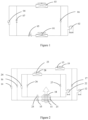
- an evaporator 01, a compressor 02, a condenser 03, a fluorine pump 04, an expansion valve 05, a one-way valve 06, and a one-way valve 07 are included. That is, a refrigeration system includes both a compressor and a fluorine pump.
- a pump mode is adopted.
- a compressor mode is adopted.
- the current refrigeration system has many disadvantages. That is, only the pump mode or the compressor mode may be operated, and there is no energy conservation effect when the pump mode and the compressor mode are operated at the same time.
- control of supply air temperature of the air conditioning unit is currently a mainstream energy conservation control mode in the industry.
- the control of supply air temperature may adapt to the needs of equipment, and also provide a prerequisite for an application of high return air.
- air paths of the two refrigeration systems are relatively independent. Therefore, supply air temperatures may not be effectively and fully mixed.
- a difference between supply air temperatures of the two refrigeration systems is quite large, making them more difficult to fully mix, causing a local hot spot in equipment that is required to be dissipated, thus reducing the reliability.
- EP 2917649 A1 discloses a cooling system includes a cabinet having an air inlet and an air outlet and a cooling circuit that includes an evaporator disposed in the cabinet, a condenser, a compressor, an expansion device and a liquid pump. Furthermore, said document discloses an air conditioning unit according to the preamble of claim 1, an operation control method for an air conditioning unit according to the preamble of claim 7 and an operation control device for an air conditioning unit according to the preamble of claim 11.
- an air conditioning unit according to claim 1
- the air conditioning unit With the air conditioning unit, the energy consumption of a system can be reduced, the energy efficiency of the system can be improved, and a very uniform supply air temperature can be ensured, which is beneficial to more accurate control of the supply air temperature.
- An air conditioning unit includes a first refrigeration system, a second refrigeration system, and a controller.
- the first refrigeration system includes a first evaporator, a first compressor, a first condenser, a first one-way valve, and a first throttling element connected in sequence in a loop as well as a second one-way valve connected in parallel with the first compressor, and a first fluorine pump connected in parallel with the first one-way valve.
- the second refrigeration system includes a second evaporator, a second compressor, a second condenser, a third one-way valve, and a second throttling element connected in sequence in a loop as well as a fourth one-way valve connected in parallel with the second compressor, and a second fluorine pump connected in parallel with the third one-way valve, where the first evaporator and the second evaporator are arranged front and rear in sequence along a return air cooling duct.
- the controller is connected to the first compressor, the first fluorine pump, the second compressor and the second fluorine pump in signal, and configured to:
- the air conditioning unit includes the first refrigeration system, the second refrigeration system, and the controller.
- the first refrigeration system and the second refrigeration system are independent of each other in a pipeline connection.
- Each refrigeration system is a complete refrigeration system integrated with the compressor and the fluorine pump.
- first evaporator in the first refrigeration system and the second evaporator in the second refrigeration system are arranged front and rear in sequence along the return air cooling duct, when the air conditioning unit operates, in the return air cooling duct, an indoor return air may first pass through the first evaporator for pre-cooling, and then pass through the second evaporator for re-cooling or supplementary cooling, so as to achieve a supply air temperature required by a machine room where the air conditioning unit is located, or a cooling capacity required by the machine room.
- a return air volume passing through the first evaporator and a return air volume passing through the second evaporator are the same.
- a return air temperature of the first refrigeration system is equivalent to a return air temperature of the machine room
- a return air temperature of the second refrigeration system is equivalent to an outlet air temperature of the first refrigeration system.
- both the first refrigeration system and the second refrigeration system have a larger indoor return air volume.
- the first fluorine pump may be controlled to work at a higher outdoor temperature, and a natural cold source may be fully utilized, thereby reducing the energy consumption of the system and achieving the purpose of energy conservation.
- the controller is configured to:
- the controller is configured to:
- the controller is configured to:
- the controller is configured to:
- first evaporator and the second evaporator are two independent heat exchangers; or the first evaporator and the second evaporator are two heat exchangers with a common fin.
- the air conditioning unit is an integrated unit or a separated unit.
- an operation control method for an air conditioning unit is further provided according to the present disclosure, which is applied to any one of the air conditioning units provided in the above technical solutions.
- the operation control method includes:
- an operation control device for an air conditioning unit which includes an acquisition unit and a control unit.
- the acquisition unit is configured to acquire a load percentage of the air conditioning unit and a difference between indoor and outdoor temperatures.
- the control unit is configured to control a working state of the first compressor, the first fluorine pump, the second compressor and the second fluorine pump based on the load percentage and the difference between indoor and outdoor temperatures.
- an air conditioning unit which includes a first refrigeration system, a second refrigeration system, and a controller.
- the first refrigeration system includes a first evaporator 11, a first compressor 12, a first condenser 13, a first one-way valve 16, and a first throttling element 15 connected in sequence in a loop as well as a second one-way valve 17 connected in parallel with the first compressor 12, and a first fluorine pump 14 connected in parallel with the first one-way valve 16.
- the second refrigeration system includes a second evaporator 21, a second compressor 22, a second condenser 23, a third one-way valve 26, and a second throttling element 25 connected in sequence in a loop as well as a fourth one-way valve 27 connected in parallel with the second compressor 22, and a second fluorine pump 24 connected in parallel with the third one-way valve 26, where the first evaporator 11 and the second evaporator 21 are arranged front and rear in sequence along a return air cooling duct.
- the controller is connected to the first compressor 12, the first fluorine pump 14, the second compressor 22 and the second fluorine pump 24 in signal, and configured to:
- the air conditioning unit includes the first refrigeration system, the second refrigeration system, and the controller.
- the first refrigeration system and the second refrigeration system are independent of each other in a pipeline connection.
- Each refrigeration system is a complete refrigeration system integrated with the compressor and the fluorine pump.
- first evaporator 11 in the first refrigeration system and the second evaporator 21 in the second refrigeration system are arranged front and rear in sequence along the return air cooling duct, when the air conditioning unit operates, in the return air cooling duct, an indoor return air may first pass through the first evaporator 11 for pre-cooling, and then pass through the second evaporator 21 for re-cooling or supplementary cooling, so as to achieve a supply air temperature required by a machine room where the air conditioning unit is located, or a cooling capacity required by the machine room.
- a return air volume passing through the first evaporator 11 and a return air volume passing through the second evaporator 21 are the same.
- a return air temperature of the first refrigeration system is equivalent to a return air temperature of the machine room
- a return air temperature of the second refrigeration system is equivalent to an outlet air temperature of the first refrigeration system.
- both the first refrigeration system and the second refrigeration system have a larger indoor return air volume.
- the first fluorine pump 14 may be controlled to work at a higher outdoor temperature, and a natural cold source may be fully utilized, thereby reducing the energy consumption of the system and achieving the purpose of energy conservation.
- the return air volume passing through the second evaporator 21 is ensured and the heat exchange capacity of the second evaporator 21 is improved.
- the first refrigeration system may be re-cooled or supplementarily cooled, and the energy consumption of the system can be reduced. Therefore, with the air conditioning unit, the high overall energy efficiency of the first refrigeration system and the second refrigeration system can be ensured.
- a first end of the return air cooling duct is connected to a return air vent of the machine room, and a second end is connected to a supply air vent of the machine room.
- the first evaporator 11 and the second evaporator 21 are arranged front and rear in sequence in the return air cooling duct.
- the load percentage may be a percentage of a currently required refrigeration capacity to a rated refrigeration capacity.
- the currently required refrigeration capacity is a heat load of the machine room.
- the currently required refrigeration capacity may be obtained from a cooling power of the machine room detected by machine room data detection equipment or a power required by the machine room, and sent by the machine room data detection equipment to the controller of the air conditioning unit.
- a first temperature sensor for measuring an indoor temperature and a second temperature sensor for measuring an outdoor temperature may also be provided in the air conditioning unit.
- the indoor temperature and the outdoor temperature are respectively detected by the first temperature sensor and the second temperature sensor.
- the difference between indoor and outdoor temperatures may be an absolute value of a difference between the indoor temperature and the outdoor temperature.
- the first evaporator 11 and the second evaporator 21 may be two independent heat exchangers; alternatively, the first evaporator 11 and the second evaporator 21 are two heat exchangers with a common fin, that is, they look like one evaporator in appearance, so that a structure of the air conditioning unit may be more compact.
- both the first evaporator 11 and the second evaporator 21 may be heat exchanging coilers in a "/" shape; alternatively, the first evaporator 11 and the second evaporator 21 may also jointly form two or more heat exchanging coilers in a "V" shape, which is not limited herein and depends on the actual situation, as long as the first evaporator 11 is located on a windward side and the second evaporator 21 is located on a leeward side along the return air cooling duct in a form of stacked coilers.
- first compressor 12 and the second compressor 22 may be single variable frequency compressors, or may be larger variable capacity compressor assemblies composed of variable frequency compressors and one or more fixed frequency compressors.
- the first condenser 13 and the second condenser 23 may also be of various types of coilers, such as a heat exchanging coiler in a "/" shape, or a heat exchanging coiler in a "V" shape. Air paths where the first condenser 13 and the second condenser 23 are located are required to be independent of each other and not interfere with each other.
- the first throttling element 15 and the second throttling element 25 may be electronic expansion valves.
- the air conditioning unit may further include an indoor air unit 18 located in the return air cooling duct, a first outdoor air unit 19 corresponding to the first condenser 13, and a second outdoor air unit 28 corresponding to the second condenser 23, as shown in Figure 2 .
- the indoor air unit 18, the first outdoor air unit 19, the second outdoor air unit 28, the first fluorine pump 14, the second fluorine pump 24, the first compressor 12 and the second compressor 22 may all be controlled by frequency conversion, to achieve accurate control under each load.
- first refrigeration system and the second refrigeration system are not limited to the structure shown in Figure 2 , and various modifications are possible.
- a liquid reservoir is added between the fluorine pump and the condenser to ensure sufficient refrigerant inside the refrigeration system;
- a switch valve is added between the compressor and the evaporator, the throttling element is connected in parallel with a switch valve, or a maintenance valve is added at both ends of the compressor.
- the air conditioning unit may be in a form of an integrated unit, that is, all components in the air conditioning unit are integrated into one integrated unit.
- the air conditioning unit may include an indoor unit part, an outdoor unit part, a compressor part, an energy conservation module part and the like.
- the indoor unit part may include the first evaporator 11, the second evaporator 21 and the like.
- the outdoor unit part may include the first condenser 13, the second condenser 23 and the like.
- the compressor part may include the first compressor 12, the second compressor 22 and the like.
- the energy conservation module part may include the first fluorine pump 14, the second fluorine pump 24 and the like.
- the first evaporator 11 and the second evaporator 21 of the air conditioning unit are located in the return air cooling duct. An inlet of the return air cooling duct is connected with a return air duct of the machine room, and an outlet of the return air cooling duct is connected with a supply air duct of the machine room.
- the air conditioning unit may also be in a form of a separated unit.
- the air conditioning unit may include an indoor unit and an outdoor unit, and a compressor part and an energy conservation module part may be arranged inside the indoor unit and the outdoor unit, respectively, or may be used as independent modules.
- each of the first refrigeration system and the second refrigeration system is a complete refrigeration system integrated with the compressor and the fluorine pump.
- the controller may control the air conditioning unit to operate in different working modes for refrigeration by controlling the first compressor 12, the first fluorine pump 14, the second compressor 22 and the second fluorine pump 24 in different states.
- the air conditioning unit operates in a compressor mode.
- the air conditioning unit operates in a mixed mode.
- the air conditioning unit operates in a fluorine pump mode.
- the controller in a case of controlling the working state of the first compressor 12, the first fluorine pump 14, the second compressor 22 and the second fluorine pump 24 based on the load percentage and the difference between indoor and outdoor temperatures, the controller may be specifically configured to:
- the air conditioning unit in a process of starting the air conditioning unit, in the case that the difference between indoor and outdoor temperatures is less than the first preset value, the air conditioning unit is controlled to operate in the compressor mode for refrigeration. In the case that the difference between indoor and outdoor temperatures is greater than or equal to the first preset value and less than the second preset value, the air conditioning unit is controlled to operate in the mixed mode for refrigeration. In the case that the difference between indoor and outdoor temperatures is greater than or equal to the second preset value, the air conditioning unit is controlled to operate in the fluorine pump mode for refrigeration.
- the air conditioning unit may be intelligently controlled to operate in different working modes for refrigeration based on the difference between indoor and outdoor temperatures, which can effectively save the energy and improve the energy efficiency of the system of the air conditioning unit.
- both the first preset value and the second preset value increase with increasing of the load percentage.
- the disadvantage of using a single temperature point is avoided, the working mode in which the air conditioning unit is required to operate may be more intelligently judged based on the indoor and outdoor temperatures and the load percentage, and the energy efficiency of the system of the air conditioning unit is improved.
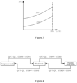
- Figure 3 is a schematic graph of changes in which a first preset value and a second preset value change with a load percentage, where x represents a load percentage, f 1 (x) represents a curve of a change of a first preset value, and fi(x) represents a curve of a change of a second preset value.
- a function of the curve of the change of the first preset value and the second preset value is not limited herein, and may be set based on parameter data obtained by a designer through an experiment.
- the air conditioning unit in a process of operating the air conditioning unit, as the outdoor temperature changes, the air conditioning unit may control the switching between various working modes for refrigeration by effectively utilizing the natural cold source, which can save the energy, and ensure the energy efficiency of the system of the air conditioning unit.
- the air conditioning unit may utilize fewer natural cold sources, and the energy efficiency of the system is relatively low.
- the air conditioning unit may utilize more natural cold sources, and the energy efficiency of the system is relatively high.
- the pump mode has the highest energy efficiency
- the compressor mode has the lowest energy efficiency.
- the outdoor temperature decreases from left to right, and the outdoor temperature increases from right to left.
- the controller of the air conditioning unit may control the switching of working modes based on a refrigeration capacity and an energy efficiency ratio of the system.
- the controller may be specifically configured to: acquire a refrigeration capacity in the compressor mode Q1, an energy efficiency ratio in the compressor mode COP1, an estimated refrigeration capacity in the mixed mode Q2', and an estimated energy efficiency ratio in the mixed mode COP2'; and in a case that the refrigeration capacity in the compressor mode Q1 is less than or equal to the estimated refrigeration capacity in the mixed mode Q2', and the energy efficiency ratio in the compressor mode COP1 is less than the estimated energy efficiency ratio in the mixed mode COP2', control the air conditioning unit to operate in the mixed mode for refrigeration.
- the air conditioning unit when the air conditioning unit operates in the compressor mode for refrigeration, as the outdoor temperature decreases, natural cold sources available for the air conditioning unit increase.
- the working mode of the air conditioning unit may be controlled to be switched from the compressor mode to the mixed mode, and the first fluorine pump 14 in the first refrigeration system works and the second compressor 22 in the second refrigeration system works.
- the natural cold source may be effectively utilized, thereby improving the energy efficiency of the system.
- the refrigeration capacity in the compressor mode Q1 is a refrigeration capacity of the air conditioning unit in the current working mode.
- the energy efficiency ratio in the compressor mode COP1 is an energy efficiency ratio of the system of the air conditioning unit in the current working mode.
- the estimated refrigeration capacity in the mixed mode Q2' is a refrigeration capacity of the air conditioning unit if operating in the mixed mode under the current outdoor temperature, which is calculated based on a calculation parameter obtained by the controller.
- the estimated energy efficiency ratio in the mixed mode COP2' is an energy efficiency ratio of the system of the air conditioning unit if operating in the mixed mode under the current outdoor temperature, which is calculated based on a calculation parameter obtained by the controller.
- the calculation parameters of the estimated refrigeration capacity in the mixed mode Q2' and the estimated energy efficiency ratio in the mixed mode COP2' are not described in detail herein, and may be calculated based on calculation formulas known in the art.
- the energy efficiency ratio of the system is a ratio of the refrigeration capacity of the air conditioning unit to the electric energy consumption.
- the controller may be specifically configured to: acquire a refrigeration capacity in the mixed mode Q2, an energy efficiency ratio in the mixed mode COP2, an estimated refrigeration capacity in the compressor mode Q1', an estimated energy efficiency ratio in the compressor mode COP1', an estimated refrigeration capacity in the fluorine pump mode Q3', and an estimated energy efficiency ratio in the fluorine pump mode COP3 ; in a case that the refrigeration capacity in the mixed mode Q2 is less than or equal to the estimated refrigeration capacity in the fluorine pump mode Q3', and the energy efficiency ratio in the mixed mode COP2 is less than the estimated energy efficiency ratio in the fluorine pump mode COP3', control the air conditioning unit to operate in the fluorine pump mode for refrigeration; and in a case that the refrigeration capacity in the mixed mode Q2 is less than or equal to the estimated refrigeration capacity in the compressor mode Q1', and the energy efficiency ratio in the mixed mode COP2 is less than the estimated energy efficiency ratio in the compressor mode,
- the air conditioning unit when the air conditioning unit operates in the mixed mode for refrigeration, as the outdoor temperature decreases, natural cold sources available for the air conditioning unit increase.
- the refrigeration capacity in the mixed mode Q2 is less than or equal to the estimated refrigeration capacity in the fluorine pump mode Q3', and the energy efficiency ratio in the mixed mode COP2 is less than the estimated energy efficiency ratio in the fluorine pump mode COP3'
- the working mode of the air conditioning unit may be controlled to be switched from the mixed mode to the fluorine pump mode.
- Both the first fluorine pump 14 of the first refrigeration system and the second fluorine pump 24 of the second refrigeration system work.
- the natural cold source may be effectively utilized, thereby improving the energy efficiency of the system.
- the refrigeration capacity in the mixed mode Q2 is a refrigeration capacity of the air conditioning unit in the current working mode.
- the energy efficiency ratio in the mixed mode COP2 is an energy efficiency ratio of the system of the air conditioning unit in the current working mode.
- the estimated refrigeration capacity in the fluorine pump mode Q3' is a refrigeration capacity of the air conditioning unit if operating in the fluorine pump mode under the current outdoor temperature, which is calculated based on a calculation parameter obtained by the controller.
- the estimated energy efficiency ratio in the fluorine pump mode COP3' is an energy efficiency ratio of the system of the air conditioning unit if operating in the fluorine pump mode under the current outdoor temperature, which is calculated based on a calculation parameter obtained by the controller.
- the calculation parameters of the estimated refrigeration capacity in the fluorine pump mode Q3' and the estimated energy efficiency ratio in the fluorine pump mode COP3' are not described in detail herein, and may be calculated based on calculation formulas known in the art.
- the working mode of the air conditioning unit may be controlled to be switched from the mixed mode to the compressor mode.
- Both the first compressor 12 of the first refrigeration system and the second compressor 22 of the second refrigeration system work, thereby improving the energy efficiency of the system.
- the refrigeration capacity in the mixed mode Q2 is a refrigeration capacity of the air conditioning unit in the current working mode.
- the energy efficiency ratio in the mixed mode COP2 is an energy efficiency ratio of the system of the air conditioning unit in the current working mode.
- the estimated refrigeration capacity in the compressor mode Q1' is a refrigeration capacity of the air conditioning unit if operating in the compressor mode under the current outdoor temperature, which is calculated based on a calculation parameter obtained by the controller.
- the estimated energy efficiency ratio in the compressor mode COP1' is an energy efficiency ratio of the system of the air conditioning unit if operating in the compressor mode under the current outdoor temperature, which is calculated based on a calculation parameter obtained by the controller.
- the calculation parameters of the estimated refrigeration capacity in the compressor mode Q1' and the estimated energy efficiency ratio in the compressor mode COP1' are not described in detail herein, and may be calculated based on calculation formulas known in the art.
- the controller is configured to: acquire a refrigeration capacity in the fluorine pump mode Q3, an energy efficiency ratio in the fluorine pump mode COP3, an estimated refrigeration capacity in the mixed mode Q2' and an estimated energy efficiency ratio in the mixed mode COP2'; and in a case that the refrigeration capacity in the fluorine pump mode Q3 is less than or equal to the estimated refrigeration capacity in the mixed mode Q2', and the energy efficiency ratio in the fluorine pump mode COP3 is less than the estimated energy efficiency ratio in the mixed mode COP2', control the air conditioning unit to operate in the mixed mode for refrigeration.
- the air conditioning unit when the air conditioning unit operates in the fluorine pump mode for refrigeration, as the outdoor temperature increases, natural cold sources available for the air conditioning unit decrease.
- the working mode of the air conditioning unit may be controlled to be switched from the fluorine pump mode to the mixed mode.
- the first fluorine pump 14 of the first refrigeration system and the second compressor 22 of the second refrigeration system work, thereby improving the energy efficiency of the system.
- the refrigeration capacity in the fluorine pump mode Q3 is a refrigeration capacity of the air conditioning unit in the current working mode.
- the energy efficiency ratio in the fluorine pump mode COP3 is an energy efficiency ratio of the system of the air conditioning unit in the current working mode.
- the estimated refrigeration capacity in the mixed mode Q2' is a refrigeration capacity of the air conditioning unit if operating in the mixed mode under the current outdoor temperature, which is calculated based on a calculation parameter obtained by the controller.
- the estimated energy efficiency ratio in the mixed mode COP2' is an energy efficiency ratio of the system of the air conditioning unit if operating in the mixed mode under the current outdoor temperature, which is calculated based on a calculation parameter obtained by the controller.
- the calculation parameters of the estimated refrigeration capacity in the mixed mode Q2' and the estimated energy efficiency ratio in the mixed mode COP2' are not described in detail herein, and may be calculated based on calculation formulas known in the art.
- the air conditioning unit determines whether to switch the working mode of the air conditioning unit is judged by using the refrigeration capacity and the energy efficiency ratio of the system, which can avoid the disadvantage of using a single outdoor temperature point to switch.
- the natural cold source may be used at a higher outdoor temperature, that is, the mixed mode or the fluorine pump mode may be operated at the higher outdoor temperature, which further improves the energy efficiency of the system of the air conditioning unit in the part-load interval.
- an operation control method for an air conditioning unit is further provided according to the present disclosure, which is applied to any one of the air conditioning units provided in the above technical solutions.
- the operation control method as shown in Figure 5 , includes the following steps S401 to S402.
- a working state of the first compressor, the first fluorine pump, the second compressor and the second fluorine pump is controlled based on the load percentage and the difference between indoor and outdoor temperatures.
- the air conditioning unit since the first evaporator in the first refrigeration system and the second evaporator in the second refrigeration system are arranged front and rear in sequence along the return air cooling duct, when the air conditioning unit operates, in the return air cooling duct, an indoor return air may first pass through the first evaporator for pre-cooling, and then pass through the second evaporator for re-cooling or supplementary cooling, so as to achieve a supply air temperature required by a machine room where the air conditioning unit is located, or a cooling capacity required by the machine room.
- the working state of the first compressor, the first fluorine pump, the second compressor and the second fluorine pump is controlled based on the load percentage and the difference between indoor and outdoor temperatures.
- the first fluorine pump may be controlled to work utilizing the natural cold source at the higher outdoor temperature, and the second compressor or the second fluorine pump may be controlled to work, to re-cool or supplementarily cool the first refrigeration system, thereby reducing the energy consumption of the system and improving the energy efficiency of the system of the air conditioning unit.
- the method includes the following operations:
- the method includes the following operations:
- the method includes the following operations:
- the method includes the following operations:
- an operation control device for an air conditioning unit is further provided according to the present disclosure, which, as shown in Figure 6 , includes an acquisition unit 100 and a control unit 200.
- the acquisition unit 100 is configured to acquire a load percentage of the air conditioning unit and a difference between indoor and outdoor temperatures.
- the control unit 200 is configured to control a working state of the first compressor, the first fluorine pump, the second compressor and the second fluorine pump based on the load percentage and the difference between indoor and outdoor temperatures.
- the operation control device for the air conditioning unit since the first evaporator in the first refrigeration system and the second evaporator in the second refrigeration system are arranged front and rear in sequence along the return air cooling duct, when the air conditioning unit operates, in the return air cooling duct, an indoor return air may first pass through the first evaporator for pre-cooling, and then pass through the second evaporator for re-cooling or supplementary cooling, so as to achieve a supply air temperature required by a machine room where the air conditioning unit is located, or a cooling capacity required by the machine room.
- the working state of the first compressor, the first fluorine pump, the second compressor and the second fluorine pump is controlled based on the load percentage and the difference between indoor and outdoor temperatures.
- the first fluorine pump may be controlled to work utilizing the natural cold source at the higher outdoor temperature, and the second compressor or the second fluorine pump may be controlled to work, to re-cool or supplementarily cool the first refrigeration system, thereby reducing the energy consumption of the system and improving the energy efficiency of the system of the air conditioning unit.
- control unit 200 in a case of controlling the working state of the first compressor, the first fluorine pump, the second compressor and the second fluorine pump based on the load percentage and the difference between indoor and outdoor temperatures, the control unit 200 is specifically configured to:
- the acquisition unit 100 is specifically configured to:
- the acquisition unit 100 is specifically configured to:
- the acquisition unit 100 is specifically configured to:
Landscapes
- Engineering & Computer Science (AREA)
- Mechanical Engineering (AREA)
- General Engineering & Computer Science (AREA)
- Physics & Mathematics (AREA)
- Thermal Sciences (AREA)
- Chemical & Material Sciences (AREA)
- Combustion & Propulsion (AREA)
- Signal Processing (AREA)
- Fuzzy Systems (AREA)
- Mathematical Physics (AREA)
- Human Computer Interaction (AREA)
- Air Conditioning Control Device (AREA)
Claims (11)
- Unité de climatisation, comprenant :un premier système de réfrigération comprenant un premier évaporateur (11), un premier compresseur (12), un premier condenseur (13), une première soupape unidirectionnelle (16), et un premier élément d'étranglement (15), raccordés en séquence en une boucle, ainsi qu'une deuxième soupape unidirectionnelle (17) raccordée en parallèle avec le premier compresseur, et une première pompe à fluor (14) raccordée en parallèle avec la première soupape unidirectionnelle ;un second système de réfrigération comprenant un second évaporateur (21), un second compresseur (22), un second condenseur (23), une troisième soupape unidirectionnelle (26), et un second élément d'étranglement (25), raccordés en séquence en une boucle, ainsi qu'une quatrième soupape unidirectionnelle (27) raccordée en parallèle avec le second compresseur, et une seconde pompe à fluor (24) raccordée en parallèle avec la troisième soupape unidirectionnelle, dans laquelle le premier évaporateur et le second évaporateur sont agencés devant et derrière en séquence le long d'un conduit de refroidissement d'air de retour ; etun organe de commande connecté au premier compresseur, à la première pompe à fluor, au second compresseur et à la seconde pompe à fluor dans signal, et configuré pour :acquérir un pourcentage de charge de l'unité de climatisation et une différence entre des températures d'intérieur et d'extérieur ; etcommander un état de mise en service du premier compresseur, de la première pompe à fluor, du second compresseur et de la seconde pompe à fluor, sur la base du pourcentage de charge et de la différence entre des températures d'intérieur et d'extérieur,caractérisée en ce que dans un cas de la commande de l'état de mise en service du premier compresseur, de la première pompe à fluor, du second compresseur et de la seconde pompe à fluor, sur la base du pourcentage de charge et de la différence entre des températures d'intérieur et d'extérieur, l'organe de commande est configuré pour :dans un cas où la différence entre des températures d'intérieur et d'extérieur est inférieure à une première valeur prédéfinie, commander le premier compresseur pour qu'il soit mis en service, la première pompe à fluor pour qu'elle ne soit pas mise en service, le second compresseur pour qu'il soit mis en service, et la seconde pompe à fluor pour qu'elle ne soit pas mise en service, pour que l'unité de climatisation fonctionne dans un mode compresseur pour la réfrigération, dans laquelle la première valeur prédéfinie augmente avec l'augmentation du pourcentage de charge ;dans un cas où la différence entre des températures d'intérieur et d'extérieur est supérieure ou égale à la première valeur prédéfinie et inférieure à une seconde valeur prédéfinie, commander le premier compresseur pour qu'il ne soit pas mis en service, la première pompe à fluor pour qu'elle soit en service, le second compresseur pour qu'il soit mis en service, et la seconde pompe à fluor pour qu'elle ne soit pas mise en service, pour que l'unité de climatisation fonctionne dans un mode mixte pour la réfrigération, dans laquelle la seconde valeur prédéfinie augmente avec l'augmentation du pourcentage de charge ; etdans un cas où la différence entre des températures d'intérieur et d'extérieur est supérieure ou égale à la seconde valeur prédéfinie, commander le premier compresseur pour qu'il ne soit pas mis en service, la première pompe à fluor pour qu'elle soit en service, le second compresseur pour qu'il ne soit pas mis en service, et la seconde pompe à fluor pour qu'elle soit en service, pour que l'unité de climatisation fonctionne dans un mode pompe à fluor pour la réfrigération.
- Unité de climatisation selon la revendication 1, dans laquelle, après que l'unité de climatisation fonctionne dans le mode compresseur pour la réfrigération, l'organe de commande est configuré pour :acquérir une capacité de réfrigération dans le mode compresseur, un rapport de rendement énergétique dans le mode compresseur, une capacité de réfrigération estimée dans le mode mixte, et un rapport de rendement énergétique estimé dans le mode mixte ; etdans un cas où la capacité de réfrigération dans le mode compresseur est inférieure ou égale à la capacité de réfrigération estimée dans le mode mixte, et le rapport de rendement énergétique dans le mode compresseur est inférieur au rapport de rendement énergétique estimé dans le mode mixte, commander l'unité de climatisation pour qu'elle fonctionne dans le mode mixte pour la réfrigération.
- Unité de climatisation selon la revendication 1, dans laquelle, après que l'unité de climatisation fonctionne dans le mode mixte pour la réfrigération, l'organe de commande est configuré pour :acquérir une capacité de réfrigération dans le mode mixte, un rapport de rendement énergétique dans le mode mixte, une capacité de réfrigération estimée dans le mode compresseur, un rapport de rendement énergétique estimé dans le mode compresseur, une capacité de réfrigération estimée dans le mode pompe à fluor, et un rapport de rendement énergétique estimé dans le mode pompe à fluor ;dans un cas où la capacité de réfrigération dans le mode mixte est inférieure ou égale à la capacité de réfrigération estimée dans le mode pompe à fluor, et le rapport de rendement énergétique dans le mode mixte est inférieur au rapport de rendement énergétique estimé dans le mode pompe à fluor, commander l'unité de climatisation pour qu'elle fonctionne dans le mode pompe à fluor pour la réfrigération ; etdans un cas où la capacité de réfrigération dans le mode mixte est inférieure ou égale à la capacité de réfrigération estimée dans le mode compresseur, et le rapport de rendement énergétique dans le mode mixte est inférieur au rapport de rendement énergétique estimé dans le mode compresseur, commander l'unité de climatisation pour qu'elle fonctionne dans le mode compresseur pour la réfrigération.
- Unité de climatisation selon la revendication 1, dans laquelle, après l'unité de climatisation fonctionne dans le mode pompe à fluor pour la réfrigération, l'organe de commande est configuré pour :acquérir une capacité de réfrigération dans le mode pompe à fluor, un rapport de rendement énergétique dans le mode pompe à fluor, une capacité de réfrigération estimée dans le mode mixte et un rapport de rendement énergétique estimé dans le mode mixte ; etdans un cas où la capacité de réfrigération dans le mode pompe à fluor est inférieure ou égale à la capacité de réfrigération estimée dans le mode mixte, et le rapport de rendement énergétique dans le mode pompe à fluor est inférieur au rapport de rendement énergétique estimé dans le mode mixte, commander l'unité de climatisation pour qu'elle fonctionne dans le mode mixte pour la réfrigération.
- Unité de climatisation selon la revendication 1, dans laquelle le premier évaporateur (11) et le second évaporateur (21) sont deux échangeurs de chaleur indépendants ; ou
le premier évaporateur et le second évaporateur sont deux échangeurs de chaleur avec une ailette commune. - Unité de climatisation selon la revendication 1, dans laquelle l'unité de climatisation est une unité intégrée ou une unité séparée.
- Procédé de commande de fonctionnement pour une unité de climatisation, appliqué sur l'unité de climatisation selon l'une quelconque des revendications 1 à 6, comprenant :l'acquisition d'un pourcentage de charge de l'unité de climatisation et d'une différence entre des températures d'intérieur et d'extérieur ; etla commande d'un état de mise en service du premier compresseur (12), de la première pompe à fluor (14), du second compresseur (22) et de la seconde pompe à fluor (24), sur la base du pourcentage de charge et de la différence entre des températures d'intérieur et d'extérieur,caractérisé en ce que dans un cas de la commande de l'état de mise en service du premier compresseur, de la première pompe à fluor, du second compresseur et de la seconde pompe à fluor, sur la base du pourcentage de charge et de la différence entre des températures d'intérieur et d'extérieur, le procédé comprend :dans un cas où la différence entre des températures d'intérieur et d'extérieur est inférieure à une première valeur prédéfinie, la commande du premier compresseur pour qu'il soit mis en service, de la première pompe à fluor pour qu'elle ne soit pas mise en service, du second compresseur pour qu'il soit mis en service, et de la seconde pompe à fluor pour qu'elle ne soit pas mise en service, pour que l'unité de climatisation fonctionne dans un mode compresseur pour la réfrigération, dans lequel la première valeur prédéfinie augmente avec l'augmentation du pourcentage de charge ;dans un cas où la différence entre des températures d'intérieur et d'extérieur est supérieure ou égale à la première valeur prédéfinie et inférieure à une seconde valeur prédéfinie, la commande du premier compresseur pour qu'il ne soit pas mis en service, de la première pompe à fluor pour qu'elle soit en service, du second compresseur pour qu'il soit mis en service, et de la seconde pompe à fluor pour qu'elle ne soit pas mise en service, pour que l'unité de climatisation fonctionne dans un mode mixte pour la réfrigération, dans lequel la seconde valeur prédéfinie augmente avec l'augmentation du pourcentage de charge ; etdans un cas où la différence entre des températures d'intérieur et d'extérieur est supérieure ou égale à la seconde valeur prédéfinie, la commande du premier compresseur pour qu'il ne soit pas mis en service, de la première pompe à fluor pour qu'elle soit en service, du second compresseur pour qu'il ne soit pas mis en service, et de la seconde pompe à fluor pour qu'elle soit en service, pour que l'unité de climatisation fonctionne dans un mode pompe à fluor pour la réfrigération.
- Procédé de commande de fonctionnement selon la revendication 7, dans lequel, après que l'unité de climatisation fonctionne dans le mode compresseur pour la réfrigération, le procédé comprend :l'acquisition d'une capacité de réfrigération dans le mode compresseur, d'un rapport de rendement énergétique dans le mode compresseur, d'une capacité de réfrigération estimée dans le mode mixte, et d'un rapport de rendement énergétique estimé dans le mode mixte ; etdans un cas où la capacité de réfrigération dans le mode compresseur est inférieure ou égale à la capacité de réfrigération estimée dans le mode mixte, et le rapport de rendement énergétique dans le mode compresseur est inférieur au rapport de rendement énergétique estimé dans le mode mixte, la commande de l'unité de climatisation pour qu'elle fonctionne dans le mode mixte pour la réfrigération.
- Procédé de commande de fonctionnement selon la revendication 7, dans lequel, après que l'unité de climatisation fonctionne dans le mode mixte pour la réfrigération, le procédé comprend :l'acquisition d'une capacité de réfrigération dans le mode mixte, d'un rapport de rendement énergétique dans le mode mixte, d'une capacité de réfrigération estimée dans le mode compresseur, d'un rapport de rendement énergétique estimé dans le mode compresseur, d'une capacité de réfrigération estimée dans le mode pompe à fluor, et d'un rapport de rendement énergétique estimé dans le mode pompe à fluor ;dans un cas où la capacité de réfrigération dans le mode mixte est inférieure ou égale à la capacité de réfrigération estimée dans le mode pompe à fluor, et le rapport de rendement énergétique dans le mode mixte est inférieur au rapport de rendement énergétique estimé dans le mode pompe à fluor, la commande de l'unité de climatisation pour qu'elle fonctionne dans le mode pompe à fluor pour la réfrigération ; etdans un cas où la capacité de réfrigération dans le mode mixte est inférieure ou égale à la capacité de réfrigération estimée dans le mode compresseur, et le rapport de rendement énergétique dans le mode mixte est inférieur au rapport de rendement énergétique estimé dans le mode compresseur, la commande de l'unité de climatisation pour qu'elle fonctionne dans le mode compresseur pour la réfrigération.
- Procédé de commande de fonctionnement selon la revendication 7, dans lequel, après que l'unité de climatisation fonctionne dans le mode pompe à fluor pour la réfrigération, le procédé comprend :
l'acquisition d'une capacité de réfrigération dans le mode pompe à fluor, d'un rapport de rendement énergétique dans le mode pompe à fluor, d'une capacité de réfrigération estimée dans le mode mixte et d'un rapport de rendement énergétique estimé dans le mode mixte ; et dans un cas où la capacité de réfrigération dans le mode pompe à fluor est inférieure ou égale à la capacité de réfrigération estimée dans le mode mixte, et le rapport de rendement énergétique dans le mode pompe à fluor est inférieur au rapport de rendement énergétique estimé dans le mode mixte, la commande de l'unité de climatisation pour qu'elle fonctionne dans le mode mixte pour la réfrigération. - Dispositif de commande de fonctionnement pour une unité de climatisation, en utilisant le procédé de commande de mise en service selon l'une quelconque des revendications 7 à 10, comprenant :une unité d'acquisition (100) configurée pour acquérir un pourcentage de charge de l'unité de climatisation et une différence entre des températures d'intérieur et d'extérieur ; etune unité de commande (200) configurée pour commander un état de mise en service du premier compresseur, de la première pompe à fluor, du second compresseur et de la seconde pompe à fluor, sur la base du pourcentage de charge et de la différence entre des températures d'intérieur et d'extérieur,caractérisé en ce que l'organe de commande est configuré en ce que dans un cas de la commande de l'état de mise en service du premier compresseur, de la première pompe à fluor, du second compresseur et de la seconde pompe à fluor, sur la base du pourcentage de charge et de la différence entre des températures d'intérieur et d'extérieur, le procédé comprend :dans un cas où la différence entre des températures d'intérieur et d'extérieur est inférieure à une première valeur prédéfinie, la commande du premier compresseur pour qu'il soit mis en service, de la première pompe à fluor pour qu'elle ne soit pas mise en service, du second compresseur pour qu'il soit mis en service, et de la seconde pompe à fluor pour qu'elle ne soit pas mise en service, pour que l'unité de climatisation fonctionne dans un mode compresseur pour la réfrigération, dans lequel la première valeur prédéfinie augmente avec l'augmentation du pourcentage de charge ;dans un cas où la différence entre des températures d'intérieur et d'extérieur est supérieure ou égale à la première valeur prédéfinie et inférieure à une seconde valeur prédéfinie, la commande du premier compresseur pour qu'il ne soit pas mis en service, de la première pompe à fluor pour qu'elle soit en service, du second compresseur pour qu'il soit mis en service, et de la seconde pompe à fluor pour qu'elle ne soit pas mise en service, pour que l'unité de climatisation fonctionne dans un mode mixte pour la réfrigération, dans lequel la seconde valeur prédéfinie augmente avec l'augmentation du pourcentage de charge ; etdans un cas où la différence entre des températures d'intérieur et d'extérieur est supérieure ou égale à la seconde valeur prédéfinie, la commande du premier compresseur pour qu'il ne soit pas mis en service, de la première pompe à fluor pour qu'elle soit en service, du second compresseur pour qu'il ne soit pas mis en service, et de la seconde pompe à fluor pour qu'elle soit en service, pour que l'unité de climatisation fonctionne dans un mode pompe à fluor pour la réfrigération.
Applications Claiming Priority (1)
| Application Number | Priority Date | Filing Date | Title |
|---|---|---|---|
| CN202111417158.5A CN116182336A (zh) | 2021-11-26 | 2021-11-26 | 一种空调机组及其运行控制方法、运行控制装置 |
Publications (2)
| Publication Number | Publication Date |
|---|---|
| EP4187178A1 EP4187178A1 (fr) | 2023-05-31 |
| EP4187178B1 true EP4187178B1 (fr) | 2024-03-06 |
Family
ID=84361593
Family Applications (1)
| Application Number | Title | Priority Date | Filing Date |
|---|---|---|---|
| EP22209236.3A Active EP4187178B1 (fr) | 2021-11-26 | 2022-11-23 | Unité de climatisation, et procédé de commande de fonctionnement et dispositif de commande de fonctionnement pour unité de climatisation |
Country Status (6)
| Country | Link |
|---|---|
| US (1) | US11988430B2 (fr) |
| EP (1) | EP4187178B1 (fr) |
| JP (1) | JP2023079196A (fr) |
| CN (1) | CN116182336A (fr) |
| AU (1) | AU2022271465B2 (fr) |
| WO (1) | WO2023092845A1 (fr) |
Families Citing this family (13)
| Publication number | Priority date | Publication date | Assignee | Title |
|---|---|---|---|---|
| CN116951713A (zh) * | 2023-08-15 | 2023-10-27 | 中创美纵信息科技(重庆)有限公司 | 冷热管机组的控制方法及系统、控制装置及可读存储介质 |
| CN117287772A (zh) * | 2023-09-12 | 2023-12-26 | 南京地铁集团有限公司 | 一种风冷房级氟泵节能空调系统 |
| CN119642424B (zh) * | 2023-09-15 | 2025-12-16 | 广东美的暖通设备有限公司 | 双循环制冷系统、控制方法、控制装置及存储介质 |
| CN119642464A (zh) * | 2023-09-15 | 2025-03-18 | 广东美的暖通设备有限公司 | 氟泵启动方法、控制装置、双循环制冷系统及存储介质 |
| CN117168018A (zh) * | 2023-09-21 | 2023-12-05 | 中国人民解放军火箭军工程设计研究院 | 一种复合式排风热回收系统及其运行优化控制方法 |
| CN118804558B (zh) * | 2024-06-28 | 2026-02-03 | 中国移动通信集团设计院有限公司 | 冷源利用系统、方法、装置、设备及计算机程序产品 |
| CN118999023B (zh) * | 2024-08-01 | 2025-11-21 | 西安工程大学 | 空调机组 |
| CN119022519A (zh) * | 2024-08-15 | 2024-11-26 | 广东申菱环境系统股份有限公司 | 一种节能型制冷系统及其控制方法 |
| CN118960269B (zh) * | 2024-08-23 | 2025-11-18 | 苏州英维克温控技术有限公司 | 氟泵压缩制冷系统的控制方法、氟泵压缩制冷系统 |
| CN119321639B (zh) * | 2024-10-15 | 2025-12-02 | 珠海格力电器股份有限公司 | 双氟泵制冷系统的控制方法、装置、设备及介质 |
| CN119594593B (zh) * | 2024-11-26 | 2025-12-02 | 深圳市英威腾网能技术有限公司 | 氟泵空调及其控制方法 |
| CN119468521B (zh) * | 2024-12-25 | 2026-01-09 | 苏州英维克温控技术有限公司 | 一种氟泵压缩制冷系统及控制方法、装置、介质 |
| CN120176330A (zh) * | 2025-03-18 | 2025-06-20 | 二冷冷气技术(浙江)有限公司 | 刀片式蒸发冷凝氟泵空调系统 |
Family Cites Families (20)
| Publication number | Priority date | Publication date | Assignee | Title |
|---|---|---|---|---|
| JP2007101093A (ja) * | 2005-10-06 | 2007-04-19 | Denso Corp | 空調装置およびその運転制御方法 |
| CN201777258U (zh) * | 2010-07-27 | 2011-03-30 | 上海科泰运输制冷设备有限公司 | 一种应用于轨道交通列车的空调机组 |
| CN102135300A (zh) * | 2011-03-04 | 2011-07-27 | 张小军 | 无需作为中间介质水主导输能的超高层建筑冷暖空调系统 |
| US9038404B2 (en) * | 2011-04-19 | 2015-05-26 | Liebert Corporation | High efficiency cooling system |
| JP5591214B2 (ja) * | 2011-11-30 | 2014-09-17 | 日立アプライアンス株式会社 | 空気調和機および空気調和機の運転方法 |
| WO2013175890A1 (fr) | 2012-05-24 | 2013-11-28 | 富士電機株式会社 | Système de climatisation, système de climatisation intégré et dispositif de commande |
| EP2917649B1 (fr) * | 2012-10-05 | 2017-09-13 | Liebert Corporation | Estimateur de charge à des fins de commande d'un système de refroidissement à compression de vapeur avec économie de frigorigène pompé |
| CN103256687B (zh) * | 2013-04-28 | 2015-10-21 | 广东美的制冷设备有限公司 | 空调器的自适应控制方法和装置 |
| CN104633867B (zh) * | 2015-02-28 | 2017-04-12 | 广东美的暖通设备有限公司 | 复合型机房空调系统及其控制方法 |
| JP6566705B2 (ja) | 2015-04-28 | 2019-08-28 | 日立ジョンソンコントロールズ空調株式会社 | 空気調和機 |
| US10254028B2 (en) | 2015-06-10 | 2019-04-09 | Vertiv Corporation | Cooling system with direct expansion and pumped refrigerant economization cooling |
| CN106855279B (zh) * | 2015-12-08 | 2022-10-25 | 维谛技术有限公司 | 一种空调系统、制冷控制方法和装置 |
| CN109237844B (zh) * | 2017-05-08 | 2021-02-19 | 维谛技术有限公司 | 空调系统、空调系统的制冷控制方法和装置 |
| CN108050719B (zh) * | 2017-12-12 | 2023-05-12 | 广东海悟科技有限公司 | 一种基于温差计算制冷剂泵能力的自然冷却系统及其控制方法 |
| CN209655448U (zh) * | 2019-01-11 | 2019-11-19 | 深圳麦克维尔空调有限公司 | 一种数据中心降温系统 |
| JP2021173420A (ja) | 2020-04-17 | 2021-11-01 | 三菱電機株式会社 | 空気調和装置 |
| CN111720901B (zh) * | 2020-06-19 | 2024-12-06 | 北京创意信通科技有限责任公司 | 一种空调室外机、空调设备及控制方法 |
| CN112097356A (zh) * | 2020-10-13 | 2020-12-18 | 南京工业大学 | 一种氟泵型机房风冷精密空调 |
| CN213873262U (zh) * | 2020-11-02 | 2021-08-03 | 广东高美空调设备有限公司 | 分体式空调 |
| CN213778222U (zh) * | 2020-11-05 | 2021-07-23 | 维谛技术有限公司 | 空调系统 |
-
2021
- 2021-11-26 CN CN202111417158.5A patent/CN116182336A/zh active Pending
-
2022
- 2022-01-20 WO PCT/CN2022/072867 patent/WO2023092845A1/fr not_active Ceased
- 2022-11-17 AU AU2022271465A patent/AU2022271465B2/en active Active
- 2022-11-23 EP EP22209236.3A patent/EP4187178B1/fr active Active
- 2022-11-24 JP JP2022187040A patent/JP2023079196A/ja active Pending
- 2022-11-24 US US17/993,960 patent/US11988430B2/en active Active
Also Published As
| Publication number | Publication date |
|---|---|
| US11988430B2 (en) | 2024-05-21 |
| EP4187178A1 (fr) | 2023-05-31 |
| AU2022271465B2 (en) | 2024-02-29 |
| AU2022271465A1 (en) | 2023-06-15 |
| US20230168016A1 (en) | 2023-06-01 |
| WO2023092845A1 (fr) | 2023-06-01 |
| JP2023079196A (ja) | 2023-06-07 |
| CN116182336A (zh) | 2023-05-30 |
Similar Documents
| Publication | Publication Date | Title |
|---|---|---|
| EP4187178B1 (fr) | Unité de climatisation, et procédé de commande de fonctionnement et dispositif de commande de fonctionnement pour unité de climatisation | |
| CN106642416B (zh) | 空调系统、复合冷凝器、空调系统的运行控制方法及装置 | |
| CN113891634B (zh) | 冷站单元、集成冷站系统及其控制方法和相关设备 | |
| CN113891635A (zh) | 冷站单元、集成冷站系统及其控制方法和相关设备 | |
| CN104266314A (zh) | 一种复合式制冷多联空调系统的控制方法 | |
| CN104251529A (zh) | 一种复合式制冷多联空调系统 | |
| JP5201183B2 (ja) | 空調装置および冷凍機の運転方法 | |
| CN216752525U (zh) | 冷站单元、集成冷站系统 | |
| CN104837323A (zh) | 一种数据中心列间散热系统 | |
| CN214420170U (zh) | 一种空调系统及汽车 | |
| EP4148347A1 (fr) | Refroidisseur d'eau à compression segmenté, à passage unique et à compresseurs multiples | |
| CN104501406A (zh) | 用于生产高温热水的多级空气源热泵 | |
| CN210951940U (zh) | 一种氟泵多联制冷系统 | |
| CN204534926U (zh) | 多联制冷系统 | |
| CN119063315A (zh) | 一种带自由冷却的风冷机组 | |
| KR101708933B1 (ko) | 냉장 장치의 냉매 순환 시스템 | |
| CN215765829U (zh) | 一种移动式液冷源的散热器调控装置 | |
| CN112519533B (zh) | 一种混合动力汽车用集成电空调系统及其控制方法 | |
| CN204063423U (zh) | 一种复合式制冷多联空调系统 | |
| JP2008070004A (ja) | 熱源システム | |
| CN113883736A (zh) | 一种移动式液冷源的散热器调控装置及调控方法 | |
| KR20080075581A (ko) | 공기조화 시스템 및 그 제어방법 | |
| CN215892827U (zh) | 热泵机组 | |
| CN222651513U (zh) | 换热系统和空调器 | |
| CN224083907U (zh) | 一种具有多冷源供应模式的背板空调系统 |
Legal Events
| Date | Code | Title | Description |
|---|---|---|---|
| PUAI | Public reference made under article 153(3) epc to a published international application that has entered the european phase |
Free format text: ORIGINAL CODE: 0009012 |
|
| STAA | Information on the status of an ep patent application or granted ep patent |
Free format text: STATUS: REQUEST FOR EXAMINATION WAS MADE |
|
| 17P | Request for examination filed |
Effective date: 20221123 |
|
| AK | Designated contracting states |
Kind code of ref document: A1 Designated state(s): AL AT BE BG CH CY CZ DE DK EE ES FI FR GB GR HR HU IE IS IT LI LT LU LV MC ME MK MT NL NO PL PT RO RS SE SI SK SM TR |
|
| GRAP | Despatch of communication of intention to grant a patent |
Free format text: ORIGINAL CODE: EPIDOSNIGR1 |
|
| STAA | Information on the status of an ep patent application or granted ep patent |
Free format text: STATUS: GRANT OF PATENT IS INTENDED |
|
| RIC1 | Information provided on ipc code assigned before grant |
Ipc: F25B 41/20 20210101ALI20231018BHEP Ipc: F25B 49/02 20060101AFI20231018BHEP |
|
| INTG | Intention to grant announced |
Effective date: 20231117 |
|
| GRAS | Grant fee paid |
Free format text: ORIGINAL CODE: EPIDOSNIGR3 |
|
| GRAA | (expected) grant |
Free format text: ORIGINAL CODE: 0009210 |
|
| STAA | Information on the status of an ep patent application or granted ep patent |
Free format text: STATUS: THE PATENT HAS BEEN GRANTED |
|
| AK | Designated contracting states |
Kind code of ref document: B1 Designated state(s): AL AT BE BG CH CY CZ DE DK EE ES FI FR GB GR HR HU IE IS IT LI LT LU LV MC ME MK MT NL NO PL PT RO RS SE SI SK SM TR |
|
| P01 | Opt-out of the competence of the unified patent court (upc) registered |
Effective date: 20240129 |
|
| REG | Reference to a national code |
Ref country code: CH Ref legal event code: EP |
|
| REG | Reference to a national code |
Ref country code: IE Ref legal event code: FG4D |
|
| REG | Reference to a national code |
Ref country code: DE Ref legal event code: R096 Ref document number: 602022002268 Country of ref document: DE |
|
| REG | Reference to a national code |
Ref country code: LT Ref legal event code: MG9D |
|
| PG25 | Lapsed in a contracting state [announced via postgrant information from national office to epo] |
Ref country code: LT Free format text: LAPSE BECAUSE OF FAILURE TO SUBMIT A TRANSLATION OF THE DESCRIPTION OR TO PAY THE FEE WITHIN THE PRESCRIBED TIME-LIMIT Effective date: 20240306 |
|
| REG | Reference to a national code |
Ref country code: NL Ref legal event code: MP Effective date: 20240306 |
|
| PG25 | Lapsed in a contracting state [announced via postgrant information from national office to epo] |
Ref country code: GR Free format text: LAPSE BECAUSE OF FAILURE TO SUBMIT A TRANSLATION OF THE DESCRIPTION OR TO PAY THE FEE WITHIN THE PRESCRIBED TIME-LIMIT Effective date: 20240607 |
|
| PG25 | Lapsed in a contracting state [announced via postgrant information from national office to epo] |
Ref country code: HR Free format text: LAPSE BECAUSE OF FAILURE TO SUBMIT A TRANSLATION OF THE DESCRIPTION OR TO PAY THE FEE WITHIN THE PRESCRIBED TIME-LIMIT Effective date: 20240306 Ref country code: RS Free format text: LAPSE BECAUSE OF FAILURE TO SUBMIT A TRANSLATION OF THE DESCRIPTION OR TO PAY THE FEE WITHIN THE PRESCRIBED TIME-LIMIT Effective date: 20240606 |
|
| PG25 | Lapsed in a contracting state [announced via postgrant information from national office to epo] |
Ref country code: ES Free format text: LAPSE BECAUSE OF FAILURE TO SUBMIT A TRANSLATION OF THE DESCRIPTION OR TO PAY THE FEE WITHIN THE PRESCRIBED TIME-LIMIT Effective date: 20240306 |
|
| PG25 | Lapsed in a contracting state [announced via postgrant information from national office to epo] |
Ref country code: RS Free format text: LAPSE BECAUSE OF FAILURE TO SUBMIT A TRANSLATION OF THE DESCRIPTION OR TO PAY THE FEE WITHIN THE PRESCRIBED TIME-LIMIT Effective date: 20240606 Ref country code: NO Free format text: LAPSE BECAUSE OF FAILURE TO SUBMIT A TRANSLATION OF THE DESCRIPTION OR TO PAY THE FEE WITHIN THE PRESCRIBED TIME-LIMIT Effective date: 20240606 Ref country code: LT Free format text: LAPSE BECAUSE OF FAILURE TO SUBMIT A TRANSLATION OF THE DESCRIPTION OR TO PAY THE FEE WITHIN THE PRESCRIBED TIME-LIMIT Effective date: 20240306 Ref country code: HR Free format text: LAPSE BECAUSE OF FAILURE TO SUBMIT A TRANSLATION OF THE DESCRIPTION OR TO PAY THE FEE WITHIN THE PRESCRIBED TIME-LIMIT Effective date: 20240306 Ref country code: GR Free format text: LAPSE BECAUSE OF FAILURE TO SUBMIT A TRANSLATION OF THE DESCRIPTION OR TO PAY THE FEE WITHIN THE PRESCRIBED TIME-LIMIT Effective date: 20240607 Ref country code: FI Free format text: LAPSE BECAUSE OF FAILURE TO SUBMIT A TRANSLATION OF THE DESCRIPTION OR TO PAY THE FEE WITHIN THE PRESCRIBED TIME-LIMIT Effective date: 20240306 Ref country code: ES Free format text: LAPSE BECAUSE OF FAILURE TO SUBMIT A TRANSLATION OF THE DESCRIPTION OR TO PAY THE FEE WITHIN THE PRESCRIBED TIME-LIMIT Effective date: 20240306 Ref country code: BG Free format text: LAPSE BECAUSE OF FAILURE TO SUBMIT A TRANSLATION OF THE DESCRIPTION OR TO PAY THE FEE WITHIN THE PRESCRIBED TIME-LIMIT Effective date: 20240306 |
|
| REG | Reference to a national code |
Ref country code: AT Ref legal event code: MK05 Ref document number: 1663896 Country of ref document: AT Kind code of ref document: T Effective date: 20240306 |
|
| PG25 | Lapsed in a contracting state [announced via postgrant information from national office to epo] |
Ref country code: SE Free format text: LAPSE BECAUSE OF FAILURE TO SUBMIT A TRANSLATION OF THE DESCRIPTION OR TO PAY THE FEE WITHIN THE PRESCRIBED TIME-LIMIT Effective date: 20240306 Ref country code: LV Free format text: LAPSE BECAUSE OF FAILURE TO SUBMIT A TRANSLATION OF THE DESCRIPTION OR TO PAY THE FEE WITHIN THE PRESCRIBED TIME-LIMIT Effective date: 20240306 |
|
| PG25 | Lapsed in a contracting state [announced via postgrant information from national office to epo] |
Ref country code: NL Free format text: LAPSE BECAUSE OF FAILURE TO SUBMIT A TRANSLATION OF THE DESCRIPTION OR TO PAY THE FEE WITHIN THE PRESCRIBED TIME-LIMIT Effective date: 20240306 |
|
| PG25 | Lapsed in a contracting state [announced via postgrant information from national office to epo] |
Ref country code: NL Free format text: LAPSE BECAUSE OF FAILURE TO SUBMIT A TRANSLATION OF THE DESCRIPTION OR TO PAY THE FEE WITHIN THE PRESCRIBED TIME-LIMIT Effective date: 20240306 |
|
| PG25 | Lapsed in a contracting state [announced via postgrant information from national office to epo] |
Ref country code: IS Free format text: LAPSE BECAUSE OF FAILURE TO SUBMIT A TRANSLATION OF THE DESCRIPTION OR TO PAY THE FEE WITHIN THE PRESCRIBED TIME-LIMIT Effective date: 20240706 |
|
| PG25 | Lapsed in a contracting state [announced via postgrant information from national office to epo] |
Ref country code: PT Free format text: LAPSE BECAUSE OF FAILURE TO SUBMIT A TRANSLATION OF THE DESCRIPTION OR TO PAY THE FEE WITHIN THE PRESCRIBED TIME-LIMIT Effective date: 20240708 Ref country code: SM Free format text: LAPSE BECAUSE OF FAILURE TO SUBMIT A TRANSLATION OF THE DESCRIPTION OR TO PAY THE FEE WITHIN THE PRESCRIBED TIME-LIMIT Effective date: 20240306 |
|
| PG25 | Lapsed in a contracting state [announced via postgrant information from national office to epo] |
Ref country code: CZ Free format text: LAPSE BECAUSE OF FAILURE TO SUBMIT A TRANSLATION OF THE DESCRIPTION OR TO PAY THE FEE WITHIN THE PRESCRIBED TIME-LIMIT Effective date: 20240306 Ref country code: EE Free format text: LAPSE BECAUSE OF FAILURE TO SUBMIT A TRANSLATION OF THE DESCRIPTION OR TO PAY THE FEE WITHIN THE PRESCRIBED TIME-LIMIT Effective date: 20240306 |
|
| PG25 | Lapsed in a contracting state [announced via postgrant information from national office to epo] |
Ref country code: AT Free format text: LAPSE BECAUSE OF FAILURE TO SUBMIT A TRANSLATION OF THE DESCRIPTION OR TO PAY THE FEE WITHIN THE PRESCRIBED TIME-LIMIT Effective date: 20240306 |
|
| PG25 | Lapsed in a contracting state [announced via postgrant information from national office to epo] |
Ref country code: PL Free format text: LAPSE BECAUSE OF FAILURE TO SUBMIT A TRANSLATION OF THE DESCRIPTION OR TO PAY THE FEE WITHIN THE PRESCRIBED TIME-LIMIT Effective date: 20240306 |
|
| PG25 | Lapsed in a contracting state [announced via postgrant information from national office to epo] |
Ref country code: SK Free format text: LAPSE BECAUSE OF FAILURE TO SUBMIT A TRANSLATION OF THE DESCRIPTION OR TO PAY THE FEE WITHIN THE PRESCRIBED TIME-LIMIT Effective date: 20240306 |
|
| PG25 | Lapsed in a contracting state [announced via postgrant information from national office to epo] |
Ref country code: SM Free format text: LAPSE BECAUSE OF FAILURE TO SUBMIT A TRANSLATION OF THE DESCRIPTION OR TO PAY THE FEE WITHIN THE PRESCRIBED TIME-LIMIT Effective date: 20240306 Ref country code: SK Free format text: LAPSE BECAUSE OF FAILURE TO SUBMIT A TRANSLATION OF THE DESCRIPTION OR TO PAY THE FEE WITHIN THE PRESCRIBED TIME-LIMIT Effective date: 20240306 Ref country code: RO Free format text: LAPSE BECAUSE OF FAILURE TO SUBMIT A TRANSLATION OF THE DESCRIPTION OR TO PAY THE FEE WITHIN THE PRESCRIBED TIME-LIMIT Effective date: 20240306 Ref country code: PT Free format text: LAPSE BECAUSE OF FAILURE TO SUBMIT A TRANSLATION OF THE DESCRIPTION OR TO PAY THE FEE WITHIN THE PRESCRIBED TIME-LIMIT Effective date: 20240708 Ref country code: PL Free format text: LAPSE BECAUSE OF FAILURE TO SUBMIT A TRANSLATION OF THE DESCRIPTION OR TO PAY THE FEE WITHIN THE PRESCRIBED TIME-LIMIT Effective date: 20240306 Ref country code: IS Free format text: LAPSE BECAUSE OF FAILURE TO SUBMIT A TRANSLATION OF THE DESCRIPTION OR TO PAY THE FEE WITHIN THE PRESCRIBED TIME-LIMIT Effective date: 20240706 Ref country code: EE Free format text: LAPSE BECAUSE OF FAILURE TO SUBMIT A TRANSLATION OF THE DESCRIPTION OR TO PAY THE FEE WITHIN THE PRESCRIBED TIME-LIMIT Effective date: 20240306 Ref country code: CZ Free format text: LAPSE BECAUSE OF FAILURE TO SUBMIT A TRANSLATION OF THE DESCRIPTION OR TO PAY THE FEE WITHIN THE PRESCRIBED TIME-LIMIT Effective date: 20240306 Ref country code: AT Free format text: LAPSE BECAUSE OF FAILURE TO SUBMIT A TRANSLATION OF THE DESCRIPTION OR TO PAY THE FEE WITHIN THE PRESCRIBED TIME-LIMIT Effective date: 20240306 |
|
| REG | Reference to a national code |
Ref country code: DE Ref legal event code: R097 Ref document number: 602022002268 Country of ref document: DE |
|
| PLBE | No opposition filed within time limit |
Free format text: ORIGINAL CODE: 0009261 |
|
| STAA | Information on the status of an ep patent application or granted ep patent |
Free format text: STATUS: NO OPPOSITION FILED WITHIN TIME LIMIT |
|
| PG25 | Lapsed in a contracting state [announced via postgrant information from national office to epo] |
Ref country code: DK Free format text: LAPSE BECAUSE OF FAILURE TO SUBMIT A TRANSLATION OF THE DESCRIPTION OR TO PAY THE FEE WITHIN THE PRESCRIBED TIME-LIMIT Effective date: 20240306 |
|
| PG25 | Lapsed in a contracting state [announced via postgrant information from national office to epo] |
Ref country code: DK Free format text: LAPSE BECAUSE OF FAILURE TO SUBMIT A TRANSLATION OF THE DESCRIPTION OR TO PAY THE FEE WITHIN THE PRESCRIBED TIME-LIMIT Effective date: 20240306 |
|
| 26N | No opposition filed |
Effective date: 20241209 |
|
| PG25 | Lapsed in a contracting state [announced via postgrant information from national office to epo] |
Ref country code: SI Free format text: LAPSE BECAUSE OF FAILURE TO SUBMIT A TRANSLATION OF THE DESCRIPTION OR TO PAY THE FEE WITHIN THE PRESCRIBED TIME-LIMIT Effective date: 20240306 |
|
| PG25 | Lapsed in a contracting state [announced via postgrant information from national office to epo] |
Ref country code: MC Free format text: LAPSE BECAUSE OF FAILURE TO SUBMIT A TRANSLATION OF THE DESCRIPTION OR TO PAY THE FEE WITHIN THE PRESCRIBED TIME-LIMIT Effective date: 20240306 |
|
| PG25 | Lapsed in a contracting state [announced via postgrant information from national office to epo] |
Ref country code: LU Free format text: LAPSE BECAUSE OF NON-PAYMENT OF DUE FEES Effective date: 20241123 |
|
| REG | Reference to a national code |
Ref country code: BE Ref legal event code: MM Effective date: 20241130 |
|
| PG25 | Lapsed in a contracting state [announced via postgrant information from national office to epo] |
Ref country code: BE Free format text: LAPSE BECAUSE OF NON-PAYMENT OF DUE FEES Effective date: 20241130 |
|
| PG25 | Lapsed in a contracting state [announced via postgrant information from national office to epo] |
Ref country code: IE Free format text: LAPSE BECAUSE OF NON-PAYMENT OF DUE FEES Effective date: 20241123 |
|
| PGFP | Annual fee paid to national office [announced via postgrant information from national office to epo] |
Ref country code: DE Payment date: 20251128 Year of fee payment: 4 |
|
| PGFP | Annual fee paid to national office [announced via postgrant information from national office to epo] |
Ref country code: IT Payment date: 20251201 Year of fee payment: 4 |
|
| PGFP | Annual fee paid to national office [announced via postgrant information from national office to epo] |
Ref country code: FR Payment date: 20251125 Year of fee payment: 4 |
|
| PG25 | Lapsed in a contracting state [announced via postgrant information from national office to epo] |
Ref country code: HU Free format text: LAPSE BECAUSE OF FAILURE TO SUBMIT A TRANSLATION OF THE DESCRIPTION OR TO PAY THE FEE WITHIN THE PRESCRIBED TIME-LIMIT; INVALID AB INITIO Effective date: 20221123 |
|
| PG25 | Lapsed in a contracting state [announced via postgrant information from national office to epo] |
Ref country code: CY Free format text: LAPSE BECAUSE OF FAILURE TO SUBMIT A TRANSLATION OF THE DESCRIPTION OR TO PAY THE FEE WITHIN THE PRESCRIBED TIME-LIMIT; INVALID AB INITIO Effective date: 20221123 |