EP4188002A1 - Procédé et appareil d'indication d'intervalle de planification - Google Patents
Procédé et appareil d'indication d'intervalle de planification Download PDFInfo
- Publication number
- EP4188002A1 EP4188002A1 EP20945940.3A EP20945940A EP4188002A1 EP 4188002 A1 EP4188002 A1 EP 4188002A1 EP 20945940 A EP20945940 A EP 20945940A EP 4188002 A1 EP4188002 A1 EP 4188002A1
- Authority
- EP
- European Patent Office
- Prior art keywords
- value
- target
- value range
- subcarrier spacing
- range
- Prior art date
- Legal status (The legal status is an assumption and is not a legal conclusion. Google has not performed a legal analysis and makes no representation as to the accuracy of the status listed.)
- Pending
Links
Images


Classifications
-
- H—ELECTRICITY
- H04—ELECTRIC COMMUNICATION TECHNIQUE
- H04W—WIRELESS COMMUNICATION NETWORKS
- H04W72/00—Local resource management
- H04W72/12—Wireless traffic scheduling
- H04W72/1263—Mapping of traffic onto schedule, e.g. scheduled allocation or multiplexing of flows
- H04W72/1268—Mapping of traffic onto schedule, e.g. scheduled allocation or multiplexing of flows of uplink data flows
-
- H—ELECTRICITY
- H04—ELECTRIC COMMUNICATION TECHNIQUE
- H04W—WIRELESS COMMUNICATION NETWORKS
- H04W72/00—Local resource management
- H04W72/20—Control channels or signalling for resource management
- H04W72/21—Control channels or signalling for resource management in the uplink direction of a wireless link, i.e. towards the network
-
- H—ELECTRICITY
- H04—ELECTRIC COMMUNICATION TECHNIQUE
- H04L—TRANSMISSION OF DIGITAL INFORMATION, e.g. TELEGRAPHIC COMMUNICATION
- H04L5/00—Arrangements affording multiple use of the transmission path
- H04L5/003—Arrangements for allocating sub-channels of the transmission path
- H04L5/0044—Allocation of payload; Allocation of data channels, e.g. PDSCH or PUSCH
-
- H—ELECTRICITY
- H04—ELECTRIC COMMUNICATION TECHNIQUE
- H04L—TRANSMISSION OF DIGITAL INFORMATION, e.g. TELEGRAPHIC COMMUNICATION
- H04L5/00—Arrangements affording multiple use of the transmission path
- H04L5/0091—Signalling for the administration of the divided path, e.g. signalling of configuration information
- H04L5/0092—Indication of how the channel is divided
-
- H—ELECTRICITY
- H04—ELECTRIC COMMUNICATION TECHNIQUE
- H04W—WIRELESS COMMUNICATION NETWORKS
- H04W72/00—Local resource management
- H04W72/04—Wireless resource allocation
- H04W72/044—Wireless resource allocation based on the type of the allocated resource
- H04W72/0446—Resources in time domain, e.g. slots or frames
Definitions
- the disclosure relates to a field of communication technologies, and particularly to a scheduling interval indication method, a scheduling interval indication apparatus, an electronic device and a computer readable storage medium.
- the base station sends Downlink Control Information (DCI) to the terminal within a downlink slot n, to schedule transmission of uplink data.
- DCI Downlink Control Information
- the base station sends the DCI to the terminal within the slot n, to schedule transmission of uplink data on a Physical Uplink Shared Channel (PUSCH) within a slot (n+k2).
- PUSCH Physical Uplink Shared Channel
- the k2 is a number of slots corresponding to a scheduling interval between the PUSCH and the corresponding DCI.
- the value of k2 may be configured by the base station for the terminal via a signaling. In the related art, the value of k2 ranges from 0 to 32, and the base station may select a value from 0 to 32 as the value of k2 and send it to the terminal.
- the length of the slot in the time domain is related to the Subcarrier Spacing (SCS).
- the terminal and the base station mainly communicate with each other in a frequency band lower than 52.6GHz.
- the SCS of the communication may be 15kHz, 30kHz, 60kHz, or 120kHz.
- the SCS is 15kHz, one slot is 1ms.
- the SCS is 30kHz, one slot is 0.5ms.
- the SCS is 60kHz, one slot is 0.25ms. That is, the larger the SCS, the shorter the length of the slot in the time domain is.
- the communication frequency band has been expanded.
- the terminal and the base station need to communicate in a frequency band above 60 GHz.
- the SCS needs to be expanded to cope with phase noises. For example, if the SCS is expanded to 960 kHz, one slot is 0.015625 ms, which is 1/64 ms.
- the length of one slot is much less than 1ms in the high-frequency band communication.
- the scheduling interval is only about 0.5 ms even if the base station selects the largest value, i.e., 32 as the value of k2. Since the processing capability of the terminal is limited, it may be difficult to complete receiving the DCI and scheduling the PUSCH according to the DCI within the scheduling interval of 0.5ms.
- the embodiments of the disclosure provide a scheduling interval indication method, a scheduling interval indication apparatus, an electronic device and a computer readable storage medium.
- a scheduling interval indication method performed by a base station.
- the method includes:
- the upper limit value is 2 n -1, and n is an integer greater than 5.
- the upper limit value is selected from a group including at least one of: 63, 127 or 255.
- the method before determining the parameter value within the first value range, the method further includes:
- an upper limit value of the target value range corresponding to the target SCS greater than or equal to 240 KHz is greater than 32.
- determining the target value range corresponding to the target SCS as the first value range includes: determining the target value range corresponding to the target SCS as the first value range based on a pre-stored first association relation between SCSs and value ranges.
- determining the target value range corresponding to the target SCS as the first value range includes:
- sending the parameter value to the terminal includes: sending the parameter value to the terminal via parameters of a Radio Resource Control (RRC) layer.
- RRC Radio Resource Control
- a scheduling interval indication apparatus applied in a base station.
- the apparatus includes:
- the upper limit value is 2 n -1, and n is an integer greater than 5.
- the upper limit value is selected from a group including at least one of: 63, 127 or 255.
- the apparatus further includes:
- an upper limit value of the target value range corresponding to the target SCS greater than or equal to 240 KHz is greater than 32.
- the range determining module is configured to: determine the target value range corresponding to the target SCS as the first value range based on a pre-stored first association relation between SCSs and value ranges.
- the range determining module is configured to: determine a target SCS range to which the target SCS belongs, and determine a target value range corresponding to the target SCS range as the first value range based on a pre-stored second association relation between SCS ranges and value ranges.
- the sending module is configured to: send the parameter value to the terminal via parameters of a Radio Resource Control (RRC) layer.
- RRC Radio Resource Control
- an electronic device includes:
- a computer readable storage medium storing computer programs.
- the computer programs are executed by a processor, the method of any of the above embodiments is implemented.
- the base station may select a value greater than 32 as the parameter value k2, and then the scheduling interval determined by the terminal according to the k2 is also larger, which facilitates the terminal with weaker processing capability to complete the receiving of the DCI and the scheduling of the PUSCH according to the DCI.
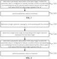
- FIG. 1 is a flowchart of a scheduling interval indication method according to the embodiment of the disclosure.
- the method shown in this embodiment may be performed by a base station, which may be, for example, a 5G base station.
- the base station may communicate with a terminal used as the user equipment (UE).
- the terminal includes, but is not limited to, a cell phone, a tablet computer, a wearable device, a sensor, an Internet of Things (IoT) device, and other electronic devices.
- IoT Internet of Things
- the scheduling interval indication method includes the following.
- a parameter value is determined within a first value range.
- the parameter value is configured to indicate a number of slots corresponding to a scheduling interval of a Physical Uplink Shared Channel (PUSCH), and an upper limit value of the first value range is greater than 32.
- PUSCH Physical Uplink Shared Channel
- the parameter value is sent to a terminal.
- the base station may determine a value within the first value range whose upper limit value is greater than 32 as the parameter value.
- the parameter value is used to indicate the number of slots corresponding to the scheduling interval of the PUSCH, i.e., k2.
- the parameter value is sent to the terminal.
- the base station can select a larger parameter value within the first value range and sends it to the terminal, so that the scheduling interval of the PUSCH may be larger to apply to the terminals with weaker processing capacity (which can be measured by the amount of data that can be processed per unit of time) to complete the receiving of the Downlink Control Information (DCI) and the scheduling of the PUSCH based on DCI.
- weaker processing capacity which can be measured by the amount of data that can be processed per unit of time
- the terminal After receiving the DCI, the terminal needs to analyze the DCI and determine a slot in which the PUSCH sends the uplink data to the base station.
- the above operations are time consuming, and it takes even longer for the terminals with lower processing capability to perform the above operations.
- the scheduling interval is short, after receiving the DCI, it is possible that the terminal needs to send the uplink data to the base station on the PUSCH when the analyzation of the DCI and the determination of the slot in which the terminal sends the uplink data to the base station on the PUSCH have not been completed or when the preparation of the uplink data has not been completed.
- the terminal does not determine the slot in which the uplink data is sent to the base station on the PUSCH or does not complete the preparation of the uplink data, problems in the communication process may occur.
- the upper limit value of the first value range is greater than 32, for example, the value range is 0 to 63, or 0 to 127
- the base station may select a value greater than 32 as the parameter value k2, and then the scheduling interval determined by the terminal according to the larger k2 is also larger.
- the scheduling interval is 2ms, which facilitates the terminal with weaker processing capability to complete the reception of the DCI and the scheduling of the PUSCH according to DCI, compared with the scheduling interval of 0.5ms in the related art.
- the upper limit value is 2n-1, and n is an integer greater than 5.
- the base station may send the parameter value determined within the first value range to the terminal via a Radio Resource Control (RRC) signaling.
- RRC Radio Resource Control
- the parameter value may be included in the PUSCH-TimeDomainResourceAllocation of the RRC signaling.
- the technical solution of the disclosure increases the upper limit value of the value range to choose the parameter value k2, such that the base station chooses a larger parameter value k2, but the parameter value chosen by the base station is within this value range.
- the parameter value can be selected according to the needs, and the parameter value does not need to be the upper limit value. For example, if the upper limit value of 127, the parameter value k2 chosen by the base station may be 5, 121 or other values.
- the specific way of choosing the parameter value within the first value range by the base station can be determined according to the actual situation, which is not limited in the embodiment.
- FIG. 2 is a flowchart of another scheduling interval indication method according to the embodiment of the disclosure. As illustrated in FIG. 2 , before determining the parameter value within the first value range, the method further includes the following.
- a target Subcarrier Spacing (SCS) for communicating with the terminal is determined.
- a target value range corresponding to the target SCS is determined as the first value range.
- the scheduling intervals may be different.
- the association relation between the SCSs and the value ranges can be preset and stored. For example, if the base station and the terminal communicate with each other based on the target SCS, and the target SCS corresponds to the target value range, the target value range can be determined as the first value range.
- an upper limit value of the target value range corresponding to the target SCS greater than or equal to 240 KHz is greater than 32.
- the duration corresponding to one slot in the time domain is not very short, so the value range in the related art can be used for the base station to obtain the parameter value k2.
- the parameter value k2 is selected between 0 and 32.
- the duration corresponding to one slot in the time domain is relatively short, and the target value range with an upper limit value greater than 32, such as a value range of 0 to 63, 0 to 127, or 0 to 255, can be selected for the base station to choose the parameter value, so that the base station can choose a larger parameter value.
- FIG. 3 is a flowchart of still another scheduling interval indication method according to the embodiment of the disclosure. As illustrated in FIG. 3 , determining the target value range corresponding to the target SCS as the first value range includes the following.
- the target value range corresponding to the target SCS is determined as the first value range based on a pre-stored first association relation between SCSs and value ranges.
- each SCS corresponds to a respective value range. That is, the pre-stored association relation between the SCSs and the value ranges may be the association relation between each SCS and its corresponding value range, which is called the first association relation.
- the base station can determine the target value range corresponding to the target SCS according to the first association relation.
- the first association relation may include a plurality of SCSs and a plurality of value ranges. For example, if the SCS is 15 KHz, the target value range determined from the plurality of value ranges according to the first association relation is 0 to 15. If the SCS is 120 KHz, the target value range determined from the plurality of value ranges according to the first association relation is 0 to 32. If the SCS is 240 KHz, the target value range determined from the plurality of value ranges according to the first association relation is 0 to 63. If the SCS is 480 KHz, the target value range determined from the plurality of value ranges according to the first association relation is 0 to 127. If the SCS is 960 KHz, the target value range determined from the plurality of value ranges according to the first association relation is 0 to 255.
- FIG. 4 is a flowchart of yet another scheduling interval indication method according to the embodiment of the disclosure. As illustrated in FIG. 4 , determining the target value range corresponding to the target SCS as the first value range includes the following.
- a target SCS range to which the target SCS belongs is determined.
- a target value range corresponding to the target SCS range is determined as the first value range based on a pre-stored second association relation between SCS ranges and value ranges.
- each SCS range corresponds to a respective value range. That is, the pre-stored association relation between the SCSs and the value ranges can be the association relation between the SCS ranges to which the SCSs belong and the value ranges, which is called the second association relation.
- the base station may first determine the target SCS range to which the target SCS belongs, and then determine the target value range corresponding to the target SCS range according to the second association relation.
- the second association relation may include a plurality of SCS ranges and a plurality of value ranges. For example, if the SCS range is 15KHz to 120KHz, the target value range determined from the plurality of value ranges according to the second association relation is 0 to 32, and when the target SCS belongs to the SCS range of 15KHz to 120KHz, the base station determines the parameter value between 0 and 32. If the SCS range is 240KHz to 960 KHz, the target value range determined from the plurality of value ranges according to the second association relation is 0 to 32, and the base station determines the parameter value between 0 and 127 when the target SCS belongs to the SCS range of 240 KHz to 960 KHz.
- FIG. 5 is a flowchart of yet another scheduling interval indication method according to the embodiment of the disclosure. As illustrated in FIG. 5 , sending the parameter value to the terminal includes the following.
- the parameter value is sent to the terminal via parameters of a RRC layer.
- the base station may send the parameter value determined within the first value range to the terminal via the RRC signaling, in which the parameter value may be included in the PUSCH-TimeDomainResourceAllocation of the RRC signaling.
- the PUSCH-TimeDomainResourceAllocation may include not only the parameter value k2, but also other contents such as mappingType.
- the base station may also send the parameter value to the terminal by other means, for example, by another signaling other than the RRC signaling, or by carrying the parameter value k2 in RRC parameters other than the PUSCH-TimeDomainResourceAllocation, which can be set as desired.
- the disclosure further provides another scheduling interval indication method including the following.
- the base station may pre-store a table for ensuring the association relation between the SCSs and the parameter values k2, determine a corresponding parameter value k2 from the table based on the SCS used in communicating with the terminal, and send the determined parameter value k2 to the terminal.
- the parameter value k2 may increase as the SCS increases.
- the disclosure also provides a scheduling interval determining method, performed by a terminal.
- the scheduling interval determining method includes: determining a scheduling interval based on the parameter value sent according to the scheduling interval indication method of any of the above embodiments.
- the terminal may determine, based on the scheduling interval, the number of slots after receiving the DCI, after which the uplink information is sent on the PUSCH.
- the disclosure also provides the embodiments of the scheduling interval indication apparatus
- FIG. 6 is a schematic diagram of a scheduling interval indication apparatus according to the embodiment of the disclosure.
- the apparatus illustrated in this embodiment may be a base station, which may be, for example, a 5G base station.
- the base station may communicate with the terminal which can be used as the user equipment.
- the terminal includes, but is not limited to, a cell phone, a tablet computer, a wearable device, a sensor, an IoT device, and other electronic devices.
- the scheduling interval indication apparatus includes: a parameter determining module 101 and a sending module 102.
- the parameter determining module 101 is configured to determine a parameter value within a first value range, in which the parameter value is configured to indicate a number of slots corresponding to a scheduling interval of a PUSCH, and an upper limit value of the first value range is greater than 32.
- the sending module 102 is configured to send the parameter value to a terminal.
- the upper limit value is 2 n -1, and n is an integer greater than 5.
- the upper limit value is selected from a group including at least one of: 63, 127 or 255.
- FIG. 7 is a schematic diagram of another scheduling interval indication apparatus according to the embodiment of the disclosure. As illustrated in FIG. 7 , the scheduling interval indication apparatus includes: a spacing determining module 103 and a range determining module 104.
- the spacing determining module 103 is configured to determine a target SCS for communicating with the terminal.
- the range determining module 104 is configured to determine a target value range corresponding to the target SCS as the first value range.
- an upper limit value of the target value range corresponding to the target SCS greater than or equal to 240 KHz is greater than 32.
- the range determining module is configured to: determine the target value range corresponding to the target SCS as the first value range based on a pre-stored first association relation between SCSs and value ranges.
- the range determining module is configured to: determine a target SCS range to which the target SCS belongs, and determine a target value range corresponding to the target SCS range as the first value range based on a pre-stored second association relation between SCS ranges and value ranges.
- the sending module is configured to: send the parameter value to the terminal via parameters of a RRC layer.
- the apparatus embodiments basically correspond to the method embodiments, the related contents can refer to part of the descriptions of the method embodiments.
- the above-described apparatus embodiments are merely schematic, the modules described above as separate components may or may not be physically separated, and the components displayed as modules may or may not be physical modules, i.e., the components may be located in one area or may be distributed to multiple network modules. Some or all of these modules can be selected according to practical needs to achieve the purpose of the solution of the disclosure. Those skilled in the art can understand and implement the solution without inventive works.
- FIG. 8 is a schematic diagram of a scheduling interval indication apparatus 800 according to the embodiment of the disclosure.
- the apparatus 800 may be provided as a base station.
- the apparatus 800 includes: a processing component 822, a wireless transmitter/receiver component 824, an antenna component 826, and a signal processing portion specific to the wireless interface.
- the processing component 822 may further include one or more processors. One of the processors in the processing component 822 may be configured to implement the scheduling interval indication method described in any of the above embodiments.
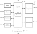
- FIG. 9 is a block diagram of a device 900 used for determining a scheduling interval according to an embodiment.
- the device 900 may be a mobile phone, a computer, a digital broadcasting terminal, a message transceiver device, a game console, a tablet device, a medical device, a fitness device and a personal digital assistant.
- the device 900 may include one or more of the following components: a processing component 902, a memory 904, a power component 906, a multimedia component 908, an audio component 910, an input/output (I/O) interface 912, a sensor component 914, and a communication component 916.
- the processing component 902 typically controls overall operations of the device 900, such as the operations associated with display, telephone calls, data communications, camera operations, and recording operations.
- the processing component 902 may include one or more processors 920 to perform all or part of the steps in the above described method.
- the processing component 902 may include one or more modules which facilitate the interaction between the processing component 902 and other components.
- the processing component 902 may include a multimedia module to facilitate the interaction between the multimedia component 908 and the processing component 902.
- the memory 904 is configured to store various types of data to support the operation of the device 900. Examples of such data include instructions for any applications or methods operated on the device 900, contact data, phonebook data, messages, pictures, video, etc.
- the memory 904 may be implemented using any type of volatile or non-volatile memory devices, or a combination thereof, such as a Static Random Access Memory (SRAM), an Electrically Erasable Programmable Read Only Memory (EEPROM), an Erasable Programmable Read Only Memory (EPROM), a Programmable Read Only Memory (PROM), a Read Only Memory (ROM), a magnetic memory, a flash memory, a magnetic or optical disk.
- SRAM Static Random Access Memory
- EEPROM Electrically Erasable Programmable Read Only Memory
- EPROM Erasable Programmable Read Only Memory
- PROM Programmable Read Only Memory
- ROM Read Only Memory
- the power component 906 provides power to various components of the device 900.
- the power component 906 may include a power management system, one or more power sources, and any other components associated with the generation, management, and distribution of power in the device 900.
- the multimedia component 908 includes a screen providing an output interface between the device 900 and the user.
- the screen may include a Liquid Crystal Display (LCD) and a Touch Panel (TP). If the screen includes the touch panel, the screen may be implemented as a touch screen to receive input signals from the user.
- the touch panel includes one or more touch sensors to sense touches, swipes, and gestures on the touch panel. The touch sensors may not only sense a boundary of a touch or swipe action, but also sense a period of time and a pressure associated with the touch or swipe action.
- the multimedia component 908 includes a front-facing camera and/or a rear-facing camera.
- the front-facing camera and/or the rear-facing camera can receive external multimedia data.
- Each front-facing camera and rear-facing camera may be a fixed optical lens system or has focal length and optical zoom capability.
- the audio component 910 is configured to output and/or input audio signals.
- the audio component 910 includes a microphone (MIC) configured to receive an external audio signal when the device 900 is in an operation mode, such as a call mode, a recording mode, and a voice recognition mode.
- the received audio signal may be further stored in the memory 904 or transmitted via the communication component 916.
- the audio component 910 further includes a speaker to output audio signals.
- the I/O interface 912 provides an interface between the processing component 902 and peripheral interface modules, such as a keyboard, a click wheel, buttons, and the like.
- the buttons may include, but are not limited to, a home button, a volume button, a starting button, and a locking button.
- the sensor component 914 includes one or more sensors to provide status assessments of various aspects of the device 900. For instance, the sensor component 914 may detect an open/closed status of the device 900, relative positioning of components, e.g., the display and the keypad, of the device 900, a change in position of the device 900 or a component of the device 900, a presence or absence of user contact with the device 900, an orientation or an acceleration/deceleration of the device 900, and a change in temperature of the device 900.
- the sensor component 914 may include a proximity sensor configured to detect the presence of nearby objects without any physical contact.
- the sensor component 914 may also include a light sensor, such as a Complementary Metal Oxide Semiconductor (CMOS) or Charge-Coupled Device (CCD) image sensor, for use in imaging applications.
- CMOS Complementary Metal Oxide Semiconductor
- CCD Charge-Coupled Device
- the sensor component 914 may also include an accelerometer sensor, a gyroscope sensor, a magnetic sensor, a pressure sensor, or a temperature sensor.
- the communication component 916 is configured to facilitate communication, wired or wirelessly, between the device 900 and other devices.
- the device 900 can access a wireless network based on a communication standard, such as WiFi, 2G, 3G, 4G LTE, 5G NR or a combination thereof.
- the communication component 916 receives a broadcast signal or broadcast associated information from an external broadcast management system via a broadcast channel.
- the communication component 916 further includes a Near Field Communication (NFC) module to facilitate short-range communication.
- NFC Near Field Communication
- the NFC module may be implemented based on a RF Identification (RFID) technology, an Infrared Data Association (IrDA) technology, an Ultra-Wide Band (UWB) technology, a Blue Tooth (BT) technology, and other technologies.
- RFID RF Identification
- IrDA Infrared Data Association
- UWB Ultra-Wide Band
- BT Blue Tooth
- the device 900 may be implemented with one or more Application Specific Integrated Circuits (ASICs), Digital Signal Processors (DSPs), Digital Signal Processing Devices (DSPDs), Programmable Logic Devices (PLDs), Field Programmable Gate Arrays (FPGAs), controllers, micro-controllers, microprocessors or other electronic components, for performing the above described method.
- ASICs Application Specific Integrated Circuits
- DSPs Digital Signal Processors
- DSPDs Digital Signal Processing Devices
- PLDs Programmable Logic Devices
- FPGAs Field Programmable Gate Arrays
- controllers micro-controllers, microprocessors or other electronic components, for performing the above described method.
- non-transitory computer readable storage medium including executable instructions, such as the memory 904, executable by the processor 920 in the device 900, for performing the above method.
- the non-transitory computer-readable storage medium may be a ROM, a Random Access Memory (RAM), a CD-ROM, a magnetic tape, a floppy disc, and an optical data storage device.
Landscapes
- Engineering & Computer Science (AREA)
- Signal Processing (AREA)
- Computer Networks & Wireless Communication (AREA)
- Mobile Radio Communication Systems (AREA)
Applications Claiming Priority (1)
| Application Number | Priority Date | Filing Date | Title |
|---|---|---|---|
| PCT/CN2020/103807 WO2022016454A1 (fr) | 2020-07-23 | 2020-07-23 | Procédé et appareil d'indication d'intervalle de planification |
Publications (2)
| Publication Number | Publication Date |
|---|---|
| EP4188002A1 true EP4188002A1 (fr) | 2023-05-31 |
| EP4188002A4 EP4188002A4 (fr) | 2024-04-17 |
Family
ID=79729936
Family Applications (1)
| Application Number | Title | Priority Date | Filing Date |
|---|---|---|---|
| EP20945940.3A Pending EP4188002A4 (fr) | 2020-07-23 | 2020-07-23 | Procédé et appareil d'indication d'intervalle de planification |
Country Status (4)
| Country | Link |
|---|---|
| US (1) | US20230269733A1 (fr) |
| EP (1) | EP4188002A4 (fr) |
| CN (1) | CN114303435B (fr) |
| WO (1) | WO2022016454A1 (fr) |
Families Citing this family (1)
| Publication number | Priority date | Publication date | Assignee | Title |
|---|---|---|---|---|
| US20240172232A1 (en) * | 2021-03-31 | 2024-05-23 | Beijing Xiaomi Mobile Software Co., Ltd. | Method and apparatus for transmitting scheduling interval information, and readable storage medium |
Family Cites Families (7)
| Publication number | Priority date | Publication date | Assignee | Title |
|---|---|---|---|---|
| US11025456B2 (en) * | 2018-01-12 | 2021-06-01 | Apple Inc. | Time domain resource allocation for mobile communication |
| CN110602769B (zh) * | 2018-06-13 | 2021-04-13 | 维沃移动通信有限公司 | 数据处理方法、用户设备和网络侧设备 |
| CN112753265B (zh) * | 2018-09-27 | 2025-02-11 | 交互数字专利控股公司 | 新无线电的未经许可的频谱中的子频带操作 |
| CN110650001A (zh) * | 2019-10-15 | 2020-01-03 | 中兴通讯股份有限公司 | 传输方法、装置、第一通信节点、第二通信节点及介质 |
| CN111163525B (zh) * | 2019-12-27 | 2022-12-30 | 京信网络系统股份有限公司 | 资源调度方法、装置、基站设备和存储介质 |
| CN113194534B (zh) * | 2020-01-14 | 2023-08-25 | 维沃移动通信有限公司 | 一种定时确定方法及通信设备 |
| US12407478B2 (en) * | 2020-02-12 | 2025-09-02 | Nec Corporation | Methods, devices and computer storage media of communication during transmission and reception |
-
2020
- 2020-07-23 WO PCT/CN2020/103807 patent/WO2022016454A1/fr not_active Ceased
- 2020-07-23 CN CN202080001616.4A patent/CN114303435B/zh active Active
- 2020-07-23 EP EP20945940.3A patent/EP4188002A4/fr active Pending
- 2020-07-23 US US18/004,249 patent/US20230269733A1/en active Pending
Also Published As
| Publication number | Publication date |
|---|---|
| WO2022016454A1 (fr) | 2022-01-27 |
| CN114303435A (zh) | 2022-04-08 |
| EP4188002A4 (fr) | 2024-04-17 |
| US20230269733A1 (en) | 2023-08-24 |
| CN114303435B (zh) | 2024-05-07 |
Similar Documents
| Publication | Publication Date | Title |
|---|---|---|
| US11197318B2 (en) | Method and apparatus for transmitting system information | |
| US20210336737A1 (en) | Measurement configuration method, apparatus, devices, system, and storage medium | |
| US11350394B2 (en) | Resource configuration method, apparatus, user equipment, and base station | |
| US20210022146A1 (en) | Method and apparatus for coordinating in-device coexistence interference, user equipment and communication device | |
| CN108476446B (zh) | 蜂窝网络中实现全双工传输的方法、装置、设备及基站 | |
| CN113796110B (zh) | 一种执行小数据包传输和确定随机接入消息传输方式的方法、装置、设备及存储介质 | |
| US20240357559A1 (en) | Configuration information sending method and apparatus, configuration information obtaining method and apparatus, communication apparatus, and storage medium | |
| US20250150876A1 (en) | Measurement method, terminal, and network device and non-transitory computer-readable storage medium | |
| US20240397283A1 (en) | Location-related information reporting and receiving methods and apparatuses | |
| US12549974B2 (en) | Method and apparatus for detecting IDC, and method and apparatus for indicating IDC detection | |
| EP3716675A1 (fr) | Procédé et dispositif d'indication de distorsion inter-modulation, station de base et équipement utilisateur | |
| US12587294B2 (en) | Modulation and coding scheme (MCS) configuration method and apparatus, and communication device | |
| US20240235784A1 (en) | Method and apparatus for transmitting or receiving system message, and communication device | |
| EP3826208A1 (fr) | Procédé et appareil de transmission de données et support de stockage | |
| US20260025802A1 (en) | Uplink transmission switching method and device, and uplink transmission switching indication method and device | |
| EP3876623B1 (fr) | Procédé de transmission d'informations, procédé de réception d'informations, station de base et terminal | |
| EP3694282B1 (fr) | Procédé de commande de communication et dispositif de commande de communication | |
| US12477533B2 (en) | Uplink scheduling method, apparatus, and storage medium | |
| EP4188002A1 (fr) | Procédé et appareil d'indication d'intervalle de planification | |
| US20240195522A1 (en) | Method for sending downlink information, method for receiving downlink information, and device | |
| US11071137B2 (en) | Data transmission method and device, and computer-readable storage medium | |
| CN109451869A (zh) | 波束选择方法及装置 | |
| CN113726494A (zh) | 传输方向的确定方法及装置 | |
| US20250151119A1 (en) | Trigger condition determination method and apparatus, and resource partition configuration method and apparatus | |
| CN116137964B (zh) | 一种传输和获取调度信息的方法、装置、设备及存储介质 |
Legal Events
| Date | Code | Title | Description |
|---|---|---|---|
| STAA | Information on the status of an ep patent application or granted ep patent |
Free format text: STATUS: THE INTERNATIONAL PUBLICATION HAS BEEN MADE |
|
| PUAI | Public reference made under article 153(3) epc to a published international application that has entered the european phase |
Free format text: ORIGINAL CODE: 0009012 |
|
| STAA | Information on the status of an ep patent application or granted ep patent |
Free format text: STATUS: REQUEST FOR EXAMINATION WAS MADE |
|
| 17P | Request for examination filed |
Effective date: 20230118 |
|
| AK | Designated contracting states |
Kind code of ref document: A1 Designated state(s): AL AT BE BG CH CY CZ DE DK EE ES FI FR GB GR HR HU IE IS IT LI LT LU LV MC MK MT NL NO PL PT RO RS SE SI SK SM TR |
|
| DAV | Request for validation of the european patent (deleted) | ||
| DAX | Request for extension of the european patent (deleted) | ||
| A4 | Supplementary search report drawn up and despatched |
Effective date: 20240315 |
|
| RIC1 | Information provided on ipc code assigned before grant |
Ipc: H04W 72/21 20230101ALI20240311BHEP Ipc: H04W 72/0446 20230101ALI20240311BHEP Ipc: H04L 5/00 20060101ALI20240311BHEP Ipc: H04W 72/04 20090101AFI20240311BHEP |
|
| STAA | Information on the status of an ep patent application or granted ep patent |
Free format text: STATUS: EXAMINATION IS IN PROGRESS |
|
| 17Q | First examination report despatched |
Effective date: 20250128 |
|
| GRAP | Despatch of communication of intention to grant a patent |
Free format text: ORIGINAL CODE: EPIDOSNIGR1 |
|
| STAA | Information on the status of an ep patent application or granted ep patent |
Free format text: STATUS: GRANT OF PATENT IS INTENDED |
|
| INTG | Intention to grant announced |
Effective date: 20260123 |