EP4189169B1 - Dispositif et procédé permettant de collecter une substance à partir d'une surface de liquide - Google Patents
Dispositif et procédé permettant de collecter une substance à partir d'une surface de liquide Download PDFInfo
- Publication number
- EP4189169B1 EP4189169B1 EP21749736.1A EP21749736A EP4189169B1 EP 4189169 B1 EP4189169 B1 EP 4189169B1 EP 21749736 A EP21749736 A EP 21749736A EP 4189169 B1 EP4189169 B1 EP 4189169B1
- Authority
- EP
- European Patent Office
- Prior art keywords
- skimmer
- mixture
- buffer vessel
- liquid
- drainage
- Prior art date
- Legal status (The legal status is an assumption and is not a legal conclusion. Google has not performed a legal analysis and makes no representation as to the accuracy of the status listed.)
- Active
Links
Images
Classifications
-
- E—FIXED CONSTRUCTIONS
- E02—HYDRAULIC ENGINEERING; FOUNDATIONS; SOIL SHIFTING
- E02B—HYDRAULIC ENGINEERING
- E02B15/00—Cleaning or keeping clear the surface of open water; Apparatus therefor
- E02B15/04—Devices for cleaning or keeping clear the surface of open water from oil or like floating materials by separating or removing these materials
- E02B15/10—Devices for removing the material from the surface
- E02B15/106—Overflow skimmers with suction heads; suction heads
-
- Y—GENERAL TAGGING OF NEW TECHNOLOGICAL DEVELOPMENTS; GENERAL TAGGING OF CROSS-SECTIONAL TECHNOLOGIES SPANNING OVER SEVERAL SECTIONS OF THE IPC; TECHNICAL SUBJECTS COVERED BY FORMER USPC CROSS-REFERENCE ART COLLECTIONS [XRACs] AND DIGESTS
- Y02—TECHNOLOGIES OR APPLICATIONS FOR MITIGATION OR ADAPTATION AGAINST CLIMATE CHANGE
- Y02A—TECHNOLOGIES FOR ADAPTATION TO CLIMATE CHANGE
- Y02A20/00—Water conservation; Efficient water supply; Efficient water use
- Y02A20/20—Controlling water pollution; Waste water treatment
- Y02A20/204—Keeping clear the surface of open water from oil spills
Definitions
- the present invention relates to a device for collecting a substance, such as crude oil from a surface of a first liquid.
- the invention further relates to a method for collecting a substance from a surface of a first liquid.
- WO 2013/112047 A1 discloses an apparatus for collecting a lighter fraction floatable liquid from a heavier fraction liquid, such as a lighter fraction floating oil from a heavier fraction water, the apparatus comprising: a floatable collecting container and a cover placed above the collecting container leaving a continuous passage slot free; wherein the opening of the passage slot is adjustable by an inlet adjustment ring.
- the invention also provides a method to operate such an apparatus.
- US 2017/0268192 A1 discloses a floatable-material harvester, including vacuum source, transport hose, and a floatable-material receiver.
- KR 2012 005491 0 A discloses a degreasing apparatus to easily suck and remove even hardened grease by melting the grease with steam.
- skimmer is known from NL2018452 .
- This known skimmer comprises a container with an open top side and a drain positioned at least a distance from the open top side, and the skimmer further comprises at least one pump connected with the substance drain and the skimmer is configured for removing a mixture collected in the container.
- the skimmer further comprises a float for providing buoyancy to the skimmer which at least partly covers the open top side and which is configured to be positioned at least a distance from the open top side, wherein an inlet canal is comprised between the open top side and the float.
- the goal of the present invention is therefore to provide a skimmer and associated methods that can effectively remove a substance from a liquid surface under variable circumstances.
- This object can be achieved by providing a skimmer in accordance with claim 1.
- a skimmer comprising a mixture inspection element enables an operator of the skimmer to inspect a composition of the mixture that is drained. By inspecting the mixture the operator can determine whether the skimmer is draining the substance effectively and act accordingly. For example, an operator cleaning up an oil spill at a remote location by pumping the mixture into a tanker using the skimmer may at some point detect via the mixture inspection element that the mixture contains mostly water. He can then redirect the output of the drainage conduit such that the mixture is no longer pumped into the tanker, preventing filling the tanker with mostly water. This has as advantage that the substance can be removed more efficiently and thus more cost effectively.
- the skimmer according to the invention can also be used to collect other substances from a liquid surface, for example collecting duckweed from a pond.
- the pump preferably comprises a hydraulic pump, but that alternatively the pump may comprise an electric pump or any other type of pump. This is done for both improving the water quality and for aesthetic reasons.
- the mixture inspection element is operatively connected to the at least one drainage connection.
- the skimmer further comprises the drainage conduit and the mixture inspection element is connected to the drainage conduit.
- the liquid surface may refer to a top layer of a first liquid, on top of which the substance, such as a second liquid or solid particles may be present.
- the substance such as a second liquid or solid particles may be present.
- the first liquid when the first liquid is a higher fraction liquid as the second liquid and the second liquid is a lower fraction liquid as a first liquid, the second liquid will float on top of the first liquid.
- solid particles such as duckweed, may float on top of the first liquid.
- an interface between the first liquid and the second liquid may comprise a mix of both liquids.
- the mixture inspection element comprises a sensor pipe connected to the drainage conduit and/or the at least one drainage connection, wherein the sensor pipe is configured to drain a sample portion of the mixture from the drainage conduit and/or the at least one drainage connection to an open end of the sensor pipe.
- Another advantage of having the mixture inspection element comprising a sensor pipe is that the mixture can be inspected at some distance from the skimmer. This is in particular importance if the distance between the skimmer and the operator is relatively large, for example in the case that the skimmer is being used at open sea, while the operator is on a larger vessel.
- the advantage of having the drainage conduit and/or the at least one drainage connection comprising a flow controller is that the quantity of liquid that is pumped to the drainage conduit can be adapted to a particular situation. For example, when a container receiving the mixture from the drainage conduit is almost or entirely full, the flow controller may be used by an operator to, directly or indirectly, temporarily lower the flow speed, or shut down the flow entirely. This is of special importance in case of a plurality of drainage conduits being used, wherein one drainage conduit should have a different flow speed.
- the advantage of having the sensor pipe comprising a flow controller is that the flow in the sensor pipe can be adapted according to the substance and/or the mixture (composition) that is being pumped.
- the substance when the substance is a second liquid, the mixture might easily pass through the sensor pipe and the flow may be restricted by the operator to prevent an abundance of the mixture being drained out of the sensor pipe.
- a relatively lower flow speed might clog up the sensor pipe. In this case the operator might control the flow in the sensor pipe to be higher using the flow controller.
- the sensor pipe extends partly within the drainage conduit and/or the at least one drainage connection. In one example, the sensor pipe extends in a first direction which is about perpendicular to the flow direction in the drainage conduit and/or drainage connection.
- the sensor pipe extends from an inner wall of the drainage connection towards a center of the drainage connection when viewed from the flow direction.
- the sensor pipe is configured to drain the hydraulic pump and/or buffer vessel after use thereof.
- the sensor pipe is configured to let an operator of the skimmer control the draining of the pump. This has as advantage that the mixture drained from the pump and/or buffer vessel can be collected and disposed thereof in an appropriate manner.
- the sensor pipe comprises a drain valve positioned at the lowest position of the sensor pipe when the skimmer is in an upright position.
- the mixture inspection element comprises a transparent section of the drainage conduit. This has the advantage that an operator can inspect the mixture flowing through the drainage conduit during use by looking at the mixture composition flowing through the drainage conduit without the mixture being spilled back in the area that is being cleaned.
- the transparent inspection element is positioned close to a position of the operator during use.
- the floatation element comprises a float and a height adjuster configured for adjusting a relative distance between the float and the buffer vessel.
- the adjustments to the relative distance between the float and the buffer vessel may be made by the operator based on his observations of the mixture using the mixture inspection element. For example, if the operator concludes from the mixture inspection element that the mixture mostly contains the first liquid, the operator may control the height adjuster to decrease the relative distance between the float and the buffer vessel. However, if the operator concludes from the mixture inspection element that there is a relatively low amount of mixture being drained, the operator may control the pump to increase a pump speed and the height adjuster to increase the relative distance between the float and the buffer vessel, such that a size of the inlet opening is increased and the mixture will flow into the buffer vessel more easily, thus increasing the speed with which the mixture being drained.
- the height adjuster comprises a hydraulic and/or mechanical system.
- the advantage of the height adjuster comprising a hydraulic system is that the height adjuster may be controlled by the operator from some distance manually and/or automatically, optionally when in operation. This is especially relevant when, for example, the skimmer is deployed at open sea and controlled by the operator from a supporting vessel, since in these cases the operator does not have easy access to the skimmer.
- the height adjuster comprises a rod connected to the float and the buffer vessel and wherein at least one of the connections between the float and the rod and the buffer vessel and the rod comprises a threaded connection. This enables the operator to change the height of the float by rotating the rod and/or float, also when in operation.
- the liquid being injected may comprise the first liquid, for example (ocean) water.
- the liquid injection system is positioned between the mixture inspection element and an outer edge of the drainage conduit and preferably near the mixture inspection element.
- the skimmer further comprises at least one liquid inlet connected to the buffer vessel and which is positioned under the liquid surface during use, and wherein each of the at least one liquid inlet comprises a valve mechanism for closing the inlet during pumping
- Having an inlet connected to the buffer vessel which is positioned under the liquid surface has as advantage that it enables an operator to let the buffer vessel at least partly fill up with liquid, such that the buffer vessel will at least partly sink below the liquid surface.
- liquid inlet may be used to drain the buffer vessel, the (hydraulic) pump, the at least one drainage connection and/or drainage conduit of remaining liquid(s) and/or substance after use of the skimmer.
- each of the at least one liquid inlet comprises a valve mechanism for closing the inlet during pumping.
- valve mechanism is connected to a hydraulics system of the at least one pump using a hydraulic manifold and wherein the valve mechanism is configured to close in correspondence with a use of the hydraulic pump.
- valve mechanism will automatically closed when the at least one pump is being used. This makes the skimmer more easy to use and does not allow the operator to accidently forget to close the valve mechanism during pumping.
- the at least one liquid inlet comprises a one-way valve configured to be closed by pressure in one or more of the at least one pump and/or drainage conduit. This has the advantage that the at least one liquid inlet will be closed automatically during use of the at least one pump.
- the buffer vessel is at least partly surrounded by an outer vessel.
- the advantage of having a cage and/or an outer vessel is that the buffer vessel and pump are protected from damages from for example collisions. This prevents leaks and other damages which would cause the skimmer to work sub-optimal.
- the outer vessel comprises one or more openings and a partly open space exists between the outer vessel and the buffer vessel configured to be filled with liquid when the skimmer is deployed.
- the inlet opening defined an inlet channel, wherein the inlet opening comprises a restriction. Having a restriction in the inlet opening has the effect that the mixture flowing into the inlet channel will come in contact with all sides of the inlet channel, resulting in an adhesive effect of the mixture with the inlet channel, having a similar effect as a capillary action, resulting in the mixture to flow into the buffer vessel more quickly due to the adhesive properties between the mixture and the inlet channel.
- the inlet channel is defined by the buffer vessel and the floating element.
- the present invention further relates to a method for removing a substance from a liquid surface, the method comprising the steps of:
- the method provides the same or similar effects and/or advantages as described in relation to the skimmer according to embodiments of the invention.
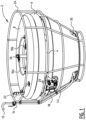
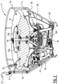
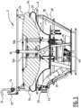
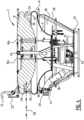
- FIG. 1-4 shows skimmer 2 according to an example of the invention for collecting a substance from a liquid surface.
- Skimmer 2 comprises a buffer vessel 4 that is provided with open top side 40, drain 42 and outer edge 6.
- Float 8 is connected with buffer vessel 4 via the height adjuster 10, which comprises hydraulic cylinders 10a, 10b, 10c. It is noted that the number of cylinders is just provided as an example and that the height adjuster 10 may comprise one or more hydraulic cylinders.
- Float 6 is configured make skimmer 2 buoyant, for example by being at least partly made from a light material such as Styrofoam or expanded polystyrene (EPS), and/or by having one or more air chambers. It will be understood that other materials could also be envisaged in accordance to the invention.
- Outer edge 6 and float 8 defines inlet opening 34, through which the mixture can enter skimmer 2 via open top side 40 to fill buffer vessel 4.
- EPS expanded polystyrene
- Buffer vessel 4 is partly surrounded by outer vessel 28 which has the function of water anchor and which is provided with outer vessel openings 30.
- liquid such as seawater
- the liquid in the dampening space 38 has the effect that waves are dampened, making skimmer 2 more stable during operation and less subjectable to waves.
- Outer vessel 28 and float 8 are surrounded by cage 24 to provide protection against impact of, for example, foreign objects which otherwise may damage skimmer 2.
- Skimmer 2 is further provided with hydraulic pump 16 connected with drain 42 of buffer vessel 4 configured for pumping the mixture from buffer vessel 4 through the drainage conduit connected to drainage connection 18 to transport the mixture to a desired location (not shown).
- hydraulic pump is configured to be connected to a pump controller (not shown) using the hydraulic connections 20. This enables an operator to operate hydraulic pump 16 from a distance. It is noted that hydraulic pump 16 is merely shown as example and that other types of pumps may be used according to the invention.
- Hydraulic connections 20 are further connected to hydraulic cylinders 10a, 10b, 10c of height adjuster 10 to enable the operator to adjust the distance between float 8 and buffer vessel 4, also adjusting the size of inlet opening 34.
- This is apparent in figure 3 , wherein hydraulic cylinders 10a, 10b, 10c are compressed and the distance between float 8 and buffer vessel 4 and corresponding inlet opening is relatively small, while in figure 4 the hydraulic cylinders 10a, 10b, 10c are extended and thus the distance between float 8 and buffer vessel 4 and corresponding inlet opening is relatively large.
- Controlling the height of float 8 may be used to adapt the size of inlet opening 34 to the substance to be cleaned.
- a layer of crude oil might be relatively thick and thus a relative large inlet opening 34 is needed to accept the mixture.
- a layer of duck weed in a pond might be relatively thin and thus a relative small inlet opening 34 is needed. It is clear that the examples provide above do not limit the invention and that the height of float 8 may be adapted differently according to a judgment of the operator.
- the operator when removing crude oil the operator might decide to adjust the height of float 8 such that inlet opening is smaller as a thickness of the crude oil layer, thus preventing an abundance of seawater to enter skimmer 2, while when removing duckweed the operator might decide to increase the height of float 8 in order to increase the speed with which the duckweed is removed.
- the operator can control how deep skimmer 2 is in the liquid during user thereof.
- buffer vessel is filled with the liquid and/or substance via primer opening 46to sink skimmer 2 to the desired depth wherein outer edge 6 is under the liquid surface.
- Depth reader 22 may be used by the operator to receive an indication of the desired depth (i.e. draft) of the skimmer and/or to receive an indication of the size of the inlet opening.
- primer opening 46 is closed by the operator using the corresponding flow controller (not shown) or primer opening 46 is configured to close in reaction of hydraulic pump 16 being switched on and to re-open in reaction of hydraulic pump 16 being switched off.
- primer opening 46 when primer opening 46 is small enough it may remain open during operation.
- buffer vessel 4 When buffer vessel 4 is filled up with the mixture outer edge 6 is under the water surface. It is hereby noted that the amount of the mixture in buffer vessel 4 partly determines the depth of skimmer 2 in the liquid. When there is a relatively large amount of the mixture in buffer vessel 4, skimmer 2 will be relatively deep in the liquid. When a relatively small amount of the mixture is in buffer vessel 4, skimmer 2 will be less deep in the liquid.
- the speed of hydraulic pump 16 the operator can control the amount of the mixture present in buffer vessel 4 and thus control the depth of skimmer 2. When the pumping speed is slower than or matches the speed with which the mixture flows into buffer vessel 4 a current depth of skimmer 2 is maintained.
- a composition of the mixture further affects the depth of skimmer 2, when the mixture contains a relatively large amount of lighter substances compared to substances in which skimmer 2 floats, skimmer 2 will be less deep compared to when the mixture contains a relatively large amount of heavier substances compared to substances in which skimmer 2 floats.
- mixture inspection element 12 can be used to gather insight on the mixture being pumped.
- a small part of the mixture will exit from one end of mixture inspection element 12.
- the operator can take appropriate actions based on his observations.
- the operator can asses that inlet opening 34 is too large and control height adjuster 10 to narrow inlet opening 34.
- the operator may asses that skimmer 2 lays too deep and may temporarily increase the speed of hydraulic pump 16 to raise skimmer 2 relative to the liquid surface.
- mixture inspection element 12 in case of a high cohesive substance such as crude oil, might not flow through mixture inspection element 12 when the mixture contains a relatively large amount of the substance. Thus, no mixture exiting mixture inspection element 12 might indicate to the operator that the mixture contains a relatively high amount of the substance. Alternatively, no mixture exiting mixture inspection element 12 may indicate that outer edge 6 is above the surface level of the liquid and that the depth of skimmer 2 should be adjusted by opening primer opening 46 and decreasing the speed of hydraulic pump 16.
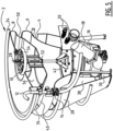
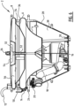
- Figures 5 and 6 show another example of a skimmer according to the invention, buffer vessel 4, with outer edge 6 that surrounds open top side 40.
- Buffer vessel 4 further has drain 42 that is connected with hydraulic pump 16 to pump the mixture from buffer vessel 4 through drainage connection 20.
- Hydraulic pump 16 is powered and controlled via hydraulics (not shown) that are connected via hydraulic connections 20.
- Skimmer 2 is further provided with sensor pipe 12 connected to drainage connection 18.
- Skimmer 2 is further provided with outer vessel 28 with inlet openings 30.
- Outer vessel 29 and buffer vessel 3 together define damping space 38.
- skimmer 2 is surrounded by cage 24 for additional protection against collisions with foreign objects.
- Lift eye 26 can be used to lift skimmer 2 in and out of the water.
- Float 8 and outer edge 6 define inlet opening 34 having a distance D and inlet channel 36, through which the mixture can enter buffer vessel 4.
- the size of the inlet opening may be changed using threaded height adjuster 32 which consists of rod 52 that is connected with float 8 and buffer vessel 4. By rotation rod 52 using adjustment wheel 54, distance D can be varied.
- Float 8 is provided with air chamber 56 to provide buoyancy to skimmer 2.
- float 8 shows steep edge 48 in skimmer 2 in figures 1-4
- float 8 shows gradual edge 50 in figures 5-6
- the steep edge 48 causes a restriction in inlet opening 34 and corresponding inlet channel 36. This has as effect that the mixture flowing into inlet channel 36 will come in contact with steep edge 48, resulting in an adhesive effect of the mixture with steep edge 48, having a similar effect as a capillary action, resulting in the mixture to flow into buffer vessel 4 more quickly due to the adhesive properties between the mixture and steep edge 48.
- angle ⁇ between average flow direction 58 and steep edge 48 is at least 70 degrees.
- skimmer 2 of figures 5-6 can also be equipped with a float with steep edge 48, while skimmer 2 of figures 1-4 can also be equipped with a float with gradual edge 50. Operation of the two skimmers in figure 1-4 and figure 5-6 are substantially similar and as described above.
Landscapes
- Engineering & Computer Science (AREA)
- General Engineering & Computer Science (AREA)
- Environmental & Geological Engineering (AREA)
- Mechanical Engineering (AREA)
- Civil Engineering (AREA)
- Structural Engineering (AREA)
- Cleaning Or Clearing Of The Surface Of Open Water (AREA)
- Removal Of Floating Material (AREA)
Claims (15)
- Écumoire (2) destinée à collecter une substance, telle que du pétrole brut, à partir d'une surface liquide, l'écumoire (2) comprenant :- un récipient tampon (4) pourvu d'une extrémité supérieure ouverte (40) et conçu pour contenir au moins temporairement un mélange de la substance à éliminer et du liquide ;- un élément de flottaison qui est agencé sur ou au niveau du récipient tampon (4) pour flotter sur la surface du liquide ; et,- au moins une pompe (16) pourvue d'au moins un raccordement de drainage (18) conçu pour être raccordé à un conduit de drainage ;dans laquelle le récipient tampon (4) comprend un bord externe (6) qui définit une ouverture d'entrée (34) pour accepter le mélange, et,dans laquelle l'au moins une pompe (16) est conçue pour pomper le mélange à partir du récipient tampon (4) à travers le conduit de drainage jusqu'à une désignation de drainage, etdans laquelle l'écumoire (2) comprend en outre un élément d'inspection de mélange (12),caractérisée en ce que,l'élément d'inspection de mélange (12) comprend un tuyau capteur raccordé au conduit de drainage et/ou à l'au moins un raccordement de drainage (18), dans laquelle le tuyau capteur est conçu pour drainer une partie d'échantillon du mélange à partir du conduit de drainage et/ou de l'au moins un raccordement de drainage (18) jusqu'à une extrémité ouverte du tuyau capteur.
- Écumoire (2) selon la revendication 1, dans laquelle l'élément d'inspection de mélange (12) est raccordé de manière opérationnelle à l'au moins un raccordement de drainage (18).
- Écumoire (2) selon la revendication 1 ou 2, dans laquelle l'écumoire (2) comprend en outre le conduit de drainage et l'élément d'inspection de mélange est raccordé au conduit de drainage.
- Écumoire (2) selon l'une quelconque des revendications précédentes, dans laquelle le conduit de drainage et/ou l'au moins un raccordement de drainage (18) et/ou le tuyau capteur comprend un contrôleur d'écoulement conçu pour contrôler une quantité du mélange qui passe à travers le conduit de drainage et/ou l'au moins un raccordement de drainage (18), et/ou le tuyau capteur pendant l'utilisation.
- Écumoire (2) selon l'une quelconque des revendications précédentes, dans laquelle le tuyau capteur s'étend partiellement au sein du conduit de drainage et/ou de l'au moins un raccordement de drainage (18).
- Écumoire (2) selon l'une quelconque des revendications précédentes, dans laquelle le tuyau capteur est conçu pour drainer la pompe (16) et/ou le récipient tampon (4) après utilisation de ceux-ci.
- Écumoire (2) selon l'une quelconque des revendications précédentes, dans laquelle l'élément d'inspection de mélange (12) comprend une section transparente du conduit de drainage.
- Écumoire (2) selon l'une quelconque des revendications précédentes, dans laquelle l'élément de flottaison comprend un flotteur (8) et un dispositif de réglage de hauteur (10) conçu pour régler une distance relative entre le flotteur (8) et le récipient tampon (4).
- Écumoire (2) selon les revendications précédentes, dans laquelle le dispositif de réglage de hauteur (10) comprend un système hydraulique (10a, 10b, 10c) et/ou
dans laquelle le dispositif de réglage de hauteur (10) comprend une tige (52) raccordée au flotteur (8) et au récipient tampon (4), et dans laquelle au moins l'un des raccords entre le flotteur (8) et la tige et le récipient tampon (4) et la tige comprend un raccordement fileté (32). - Écumoire (2) selon l'une quelconque des revendications précédentes, dans laquelle l'écumoire (2) comprend en outre un système d'injection de liquide conçu pour injecter du liquide dans le conduit de drainage et augmenter la vitesse d'écoulement dans le conduit de drainage, dans laquelle le système d'injection d'eau est de préférence positionné entre l'élément d'inspection de mélange (12) et une extrémité externe du conduit de drainage.
- Écumoire (2) selon l'une quelconque des revendications précédentes, dans laquelle l'écumoire (2) comprend en outre au moins une entrée de liquide raccordée au récipient tampon (4) et qui est positionnée sous la surface de liquide pendant l'utilisation, et dans laquelle chacune de l'au moins une entrée de liquide comprend un mécanisme de vanne pour fermer l'entrée pendant le pompage, dans laquelle les une ou plusieurs pompes (16) comprennent de préférence une pompe hydraulique et dans laquelle le mécanisme de vanne est raccordé à un système hydraulique de l'au moins une pompe à l'aide d'un collecteur hydraulique et dans laquelle le mécanisme de vanne est conçu pour se fermer en fonction d'une utilisation de l'au moins une pompe (16), et/ou dans laquelle l'au moins une entrée de liquide comprend de préférence une vanne à sens unique conçue pour être fermée par la pression dans une ou plusieurs de l'au moins une pompe (16), l'au moins un raccordement de drainage (18), et/ou le conduit de drainage.
- Écumoire (2) selon l'une quelconque des revendications précédentes, dans laquelle le récipient tampon (4) est au moins partiellement entouré d'une cage et/ou d'un récipient externe, et dans laquelle de préférence le récipient externe (28) comprend une ou plusieurs ouvertures, et dans laquelle de préférence un espace partiellement ouvert existe entre le récipient externe (28) et le récipient tampon (4) conçu pour être rempli d'un liquide lorsque l'écumoire (2) est déployée.
- Écumoire (2) selon l'une quelconque des revendications précédentes, dans laquelle l'ouverture d'entrée (34) définit un canal d'entrée (36), et dans laquelle le canal d'entrée (36) comprend une restriction sur une certaine distance, dans laquelle le canal d'entrée (36) est de préférence défini par le récipient tampon (4) et l'élément flottant, et dans laquelle l'élément flottant comprend plus préférablement un bord (18) ayant une surface de bord qui fait un angle d'au moins 70° avec une direction d'écoulement d'entrée moyenne (58) du mélange s'écoulant dans le récipient tampon (4).
- Procédé d'élimination d'une substance à partir d'une surface liquide, le procédé comprenant les étapes consistant à :- fournir une écumoire (2) selon l'une quelconque des revendications précédentes ;- positionner l'écumoire (2) dans le liquide ;- laisser le mélange s'écouler dans le récipient tampon (4) ;- pomper le mélange à partir du récipient tampon (4) ;- observer une consistance de mélange à travers l'élément d'inspection de mélange (12).
- Procédé selon la revendication 14, comprenant en outre une ou plusieurs des étapes consistant à :- diriger une sortie du conduit de drainage correspondant à l'observation de la consistance de mélange ;- adapter une distance entre le récipient tampon (4) et l'élément flottant à l'aide du contrôleur de hauteur ;- adapter une quantité de mélange dans le récipient tampon (4) en modifiant une vitesse de pompage de la pompe (16).
Applications Claiming Priority (2)
| Application Number | Priority Date | Filing Date | Title |
|---|---|---|---|
| NL2026150A NL2026150B1 (en) | 2020-07-28 | 2020-07-28 | Device and method for collecting a substance from a liquid surface |
| PCT/NL2021/050479 WO2022025764A1 (fr) | 2020-07-28 | 2021-07-27 | Dispositif et procédé permettant de collecter une substance à partir d'une surface de liquide |
Publications (3)
| Publication Number | Publication Date |
|---|---|
| EP4189169A1 EP4189169A1 (fr) | 2023-06-07 |
| EP4189169B1 true EP4189169B1 (fr) | 2024-09-04 |
| EP4189169C0 EP4189169C0 (fr) | 2024-09-04 |
Family
ID=72886138
Family Applications (1)
| Application Number | Title | Priority Date | Filing Date |
|---|---|---|---|
| EP21749736.1A Active EP4189169B1 (fr) | 2020-07-28 | 2021-07-27 | Dispositif et procédé permettant de collecter une substance à partir d'une surface de liquide |
Country Status (5)
| Country | Link |
|---|---|
| US (1) | US20240175225A1 (fr) |
| EP (1) | EP4189169B1 (fr) |
| NL (1) | NL2026150B1 (fr) |
| SA (1) | SA523442327B1 (fr) |
| WO (1) | WO2022025764A1 (fr) |
Families Citing this family (2)
| Publication number | Priority date | Publication date | Assignee | Title |
|---|---|---|---|---|
| CN113309057B (zh) * | 2021-07-07 | 2022-12-13 | 江苏中科基业环境科技有限公司 | 双浮力系统汲取机 |
| TWI869309B (zh) * | 2024-07-05 | 2025-01-01 | 劉愉如 | 除油裝置 |
Family Cites Families (4)
| Publication number | Priority date | Publication date | Assignee | Title |
|---|---|---|---|---|
| KR20120054910A (ko) * | 2010-11-22 | 2012-05-31 | 최유근 | 증기를 이용한 기름 제거 장치 |
| NL2008164C2 (en) * | 2012-01-23 | 2013-07-25 | Environment Solutions B V | Apparatus and method for collecting a floatable liquid. |
| WO2014205544A1 (fr) * | 2013-06-23 | 2014-12-31 | Jonathan Karl Wayne Biley | Système pour récolter des algues et produire de l'éthanol à partir de ces dernières |
| NL2018452B1 (en) | 2017-03-01 | 2018-09-21 | Env Solutions B V | Device and method for collecting a floatable liquid |
-
2020
- 2020-07-28 NL NL2026150A patent/NL2026150B1/en active
-
2021
- 2021-07-27 US US18/017,805 patent/US20240175225A1/en active Pending
- 2021-07-27 WO PCT/NL2021/050479 patent/WO2022025764A1/fr not_active Ceased
- 2021-07-27 EP EP21749736.1A patent/EP4189169B1/fr active Active
-
2023
- 2023-01-26 SA SA523442327A patent/SA523442327B1/ar unknown
Also Published As
| Publication number | Publication date |
|---|---|
| NL2026150B1 (en) | 2022-03-29 |
| WO2022025764A1 (fr) | 2022-02-03 |
| US20240175225A1 (en) | 2024-05-30 |
| EP4189169C0 (fr) | 2024-09-04 |
| SA523442327B1 (ar) | 2024-06-02 |
| EP4189169A1 (fr) | 2023-06-07 |
Similar Documents
| Publication | Publication Date | Title |
|---|---|---|
| US20160318776A1 (en) | Apparatus for separating and collecting oil spilled in ocean | |
| KR100728801B1 (ko) | 호소 침전물 처리장치 | |
| EP4189169B1 (fr) | Dispositif et procédé permettant de collecter une substance à partir d'une surface de liquide | |
| US5713697A (en) | Oil-extraction station | |
| US11959248B2 (en) | Device for the removal of sludge and/or sand from the bottom of a wetland | |
| JP2001009204A (ja) | 油水分離装置 | |
| EP4019700A1 (fr) | Dispositif de récupération d'huile à haute viscosité pour les marées noires et procédé associé | |
| NO316628B1 (no) | Fremgangsmate og anordning for hydraulisk fjerning av sedimenter fra sandfang | |
| CN104169501B (zh) | 收集漂浮液体的装置和方法 | |
| KR101911497B1 (ko) | 무전원 침수방지 장치 | |
| CA2803024C (fr) | Dispositif et procede pour eliminer un liquide d'une surface d'eau | |
| US7678285B2 (en) | Apparatus and method for separation of water from an emulsion or mixture of water and oil | |
| EP0682553B1 (fr) | Appareil de drainage de petrole et d'eau d'une surface, notamment du pont d'un petrolier | |
| EP0007891B1 (fr) | Procédé et dispositif pour recueillir l'huile flottant sur l'eau | |
| NL2018452B1 (en) | Device and method for collecting a floatable liquid | |
| GB2481080A (en) | Oil recovery vessel | |
| AU2024381469A1 (en) | Device for removing sludge and/or sand from the bottom of a water body | |
| WO2007035152A1 (fr) | Appareil et procédé de séparation d’eau à partir d’une émulsion ou d’un mélange d’eau et d’huile | |
| RU2372444C2 (ru) | Устройство для сбора нефтепродуктов с водной поверхности | |
| HK1204485B (en) | Apparatus and method for collecting a floatable liquid |
Legal Events
| Date | Code | Title | Description |
|---|---|---|---|
| STAA | Information on the status of an ep patent application or granted ep patent |
Free format text: STATUS: UNKNOWN |
|
| STAA | Information on the status of an ep patent application or granted ep patent |
Free format text: STATUS: THE INTERNATIONAL PUBLICATION HAS BEEN MADE |
|
| PUAI | Public reference made under article 153(3) epc to a published international application that has entered the european phase |
Free format text: ORIGINAL CODE: 0009012 |
|
| STAA | Information on the status of an ep patent application or granted ep patent |
Free format text: STATUS: REQUEST FOR EXAMINATION WAS MADE |
|
| 17P | Request for examination filed |
Effective date: 20230222 |
|
| AK | Designated contracting states |
Kind code of ref document: A1 Designated state(s): AL AT BE BG CH CY CZ DE DK EE ES FI FR GB GR HR HU IE IS IT LI LT LU LV MC MK MT NL NO PL PT RO RS SE SI SK SM TR |
|
| DAV | Request for validation of the european patent (deleted) | ||
| DAX | Request for extension of the european patent (deleted) | ||
| GRAP | Despatch of communication of intention to grant a patent |
Free format text: ORIGINAL CODE: EPIDOSNIGR1 |
|
| STAA | Information on the status of an ep patent application or granted ep patent |
Free format text: STATUS: GRANT OF PATENT IS INTENDED |
|
| INTG | Intention to grant announced |
Effective date: 20240322 |
|
| GRAS | Grant fee paid |
Free format text: ORIGINAL CODE: EPIDOSNIGR3 |
|
| GRAA | (expected) grant |
Free format text: ORIGINAL CODE: 0009210 |
|
| STAA | Information on the status of an ep patent application or granted ep patent |
Free format text: STATUS: THE PATENT HAS BEEN GRANTED |
|
| AK | Designated contracting states |
Kind code of ref document: B1 Designated state(s): AL AT BE BG CH CY CZ DE DK EE ES FI FR GB GR HR HU IE IS IT LI LT LU LV MC MK MT NL NO PL PT RO RS SE SI SK SM TR |
|
| REG | Reference to a national code |
Ref country code: GB Ref legal event code: FG4D |
|
| REG | Reference to a national code |
Ref country code: CH Ref legal event code: EP |
|
| REG | Reference to a national code |
Ref country code: IE Ref legal event code: FG4D |
|
| REG | Reference to a national code |
Ref country code: DE Ref legal event code: R096 Ref document number: 602021018372 Country of ref document: DE |
|
| U01 | Request for unitary effect filed |
Effective date: 20240913 |
|
| U07 | Unitary effect registered |
Designated state(s): AT BE BG DE DK EE FI FR IT LT LU LV MT NL PT RO SE SI Effective date: 20241007 |
|
| PG25 | Lapsed in a contracting state [announced via postgrant information from national office to epo] |
Ref country code: GR Free format text: LAPSE BECAUSE OF FAILURE TO SUBMIT A TRANSLATION OF THE DESCRIPTION OR TO PAY THE FEE WITHIN THE PRESCRIBED TIME-LIMIT Effective date: 20241205 Ref country code: PL Free format text: LAPSE BECAUSE OF FAILURE TO SUBMIT A TRANSLATION OF THE DESCRIPTION OR TO PAY THE FEE WITHIN THE PRESCRIBED TIME-LIMIT Effective date: 20240904 |
|
| PG25 | Lapsed in a contracting state [announced via postgrant information from national office to epo] |
Ref country code: HR Free format text: LAPSE BECAUSE OF FAILURE TO SUBMIT A TRANSLATION OF THE DESCRIPTION OR TO PAY THE FEE WITHIN THE PRESCRIBED TIME-LIMIT Effective date: 20240904 |
|
| PG25 | Lapsed in a contracting state [announced via postgrant information from national office to epo] |
Ref country code: RS Free format text: LAPSE BECAUSE OF FAILURE TO SUBMIT A TRANSLATION OF THE DESCRIPTION OR TO PAY THE FEE WITHIN THE PRESCRIBED TIME-LIMIT Effective date: 20241204 Ref country code: ES Free format text: LAPSE BECAUSE OF FAILURE TO SUBMIT A TRANSLATION OF THE DESCRIPTION OR TO PAY THE FEE WITHIN THE PRESCRIBED TIME-LIMIT Effective date: 20240904 |
|
| PG25 | Lapsed in a contracting state [announced via postgrant information from national office to epo] |
Ref country code: RS Free format text: LAPSE BECAUSE OF FAILURE TO SUBMIT A TRANSLATION OF THE DESCRIPTION OR TO PAY THE FEE WITHIN THE PRESCRIBED TIME-LIMIT Effective date: 20241204 Ref country code: PL Free format text: LAPSE BECAUSE OF FAILURE TO SUBMIT A TRANSLATION OF THE DESCRIPTION OR TO PAY THE FEE WITHIN THE PRESCRIBED TIME-LIMIT Effective date: 20240904 Ref country code: HR Free format text: LAPSE BECAUSE OF FAILURE TO SUBMIT A TRANSLATION OF THE DESCRIPTION OR TO PAY THE FEE WITHIN THE PRESCRIBED TIME-LIMIT Effective date: 20240904 Ref country code: GR Free format text: LAPSE BECAUSE OF FAILURE TO SUBMIT A TRANSLATION OF THE DESCRIPTION OR TO PAY THE FEE WITHIN THE PRESCRIBED TIME-LIMIT Effective date: 20241205 Ref country code: ES Free format text: LAPSE BECAUSE OF FAILURE TO SUBMIT A TRANSLATION OF THE DESCRIPTION OR TO PAY THE FEE WITHIN THE PRESCRIBED TIME-LIMIT Effective date: 20240904 |
|
| PG25 | Lapsed in a contracting state [announced via postgrant information from national office to epo] |
Ref country code: IS Free format text: LAPSE BECAUSE OF FAILURE TO SUBMIT A TRANSLATION OF THE DESCRIPTION OR TO PAY THE FEE WITHIN THE PRESCRIBED TIME-LIMIT Effective date: 20250104 |
|
| PG25 | Lapsed in a contracting state [announced via postgrant information from national office to epo] |
Ref country code: SM Free format text: LAPSE BECAUSE OF FAILURE TO SUBMIT A TRANSLATION OF THE DESCRIPTION OR TO PAY THE FEE WITHIN THE PRESCRIBED TIME-LIMIT Effective date: 20240904 |
|
| PG25 | Lapsed in a contracting state [announced via postgrant information from national office to epo] |
Ref country code: CZ Free format text: LAPSE BECAUSE OF FAILURE TO SUBMIT A TRANSLATION OF THE DESCRIPTION OR TO PAY THE FEE WITHIN THE PRESCRIBED TIME-LIMIT Effective date: 20240904 |
|
| PG25 | Lapsed in a contracting state [announced via postgrant information from national office to epo] |
Ref country code: SK Free format text: LAPSE BECAUSE OF FAILURE TO SUBMIT A TRANSLATION OF THE DESCRIPTION OR TO PAY THE FEE WITHIN THE PRESCRIBED TIME-LIMIT Effective date: 20240904 |
|
| PLBE | No opposition filed within time limit |
Free format text: ORIGINAL CODE: 0009261 |
|
| STAA | Information on the status of an ep patent application or granted ep patent |
Free format text: STATUS: NO OPPOSITION FILED WITHIN TIME LIMIT |
|
| 26N | No opposition filed |
Effective date: 20250605 |
|
| U20 | Renewal fee for the european patent with unitary effect paid |
Year of fee payment: 5 Effective date: 20250728 |
|
| PGFP | Annual fee paid to national office [announced via postgrant information from national office to epo] |
Ref country code: NO Payment date: 20250729 Year of fee payment: 5 |
|
| PGFP | Annual fee paid to national office [announced via postgrant information from national office to epo] |
Ref country code: GB Payment date: 20250728 Year of fee payment: 5 |
|
| REG | Reference to a national code |
Ref country code: CH Ref legal event code: H13 Free format text: ST27 STATUS EVENT CODE: U-0-0-H10-H13 (AS PROVIDED BY THE NATIONAL OFFICE) Effective date: 20260224 |
|
| PG25 | Lapsed in a contracting state [announced via postgrant information from national office to epo] |
Ref country code: CH Free format text: LAPSE BECAUSE OF NON-PAYMENT OF DUE FEES Effective date: 20250731 |