EP4189303B1 - Heizsystem - Google Patents
Heizsystem Download PDFInfo
- Publication number
- EP4189303B1 EP4189303B1 EP21742432.4A EP21742432A EP4189303B1 EP 4189303 B1 EP4189303 B1 EP 4189303B1 EP 21742432 A EP21742432 A EP 21742432A EP 4189303 B1 EP4189303 B1 EP 4189303B1
- Authority
- EP
- European Patent Office
- Prior art keywords
- flue gas
- heat exchanger
- air
- water
- ashp
- Prior art date
- Legal status (The legal status is an assumption and is not a legal conclusion. Google has not performed a legal analysis and makes no representation as to the accuracy of the status listed.)
- Active
Links
Images




Classifications
-
- F—MECHANICAL ENGINEERING; LIGHTING; HEATING; WEAPONS; BLASTING
- F24—HEATING; RANGES; VENTILATING
- F24D—DOMESTIC- OR SPACE-HEATING SYSTEMS, e.g. CENTRAL HEATING SYSTEMS; DOMESTIC HOT-WATER SUPPLY SYSTEMS; ELEMENTS OR COMPONENTS THEREFOR
- F24D17/00—Domestic hot-water supply systems
- F24D17/0005—Domestic hot-water supply systems using recuperation of waste heat
-
- F—MECHANICAL ENGINEERING; LIGHTING; HEATING; WEAPONS; BLASTING
- F24—HEATING; RANGES; VENTILATING
- F24D—DOMESTIC- OR SPACE-HEATING SYSTEMS, e.g. CENTRAL HEATING SYSTEMS; DOMESTIC HOT-WATER SUPPLY SYSTEMS; ELEMENTS OR COMPONENTS THEREFOR
- F24D17/00—Domestic hot-water supply systems
- F24D17/02—Domestic hot-water supply systems using heat pumps
-
- F—MECHANICAL ENGINEERING; LIGHTING; HEATING; WEAPONS; BLASTING
- F24—HEATING; RANGES; VENTILATING
- F24D—DOMESTIC- OR SPACE-HEATING SYSTEMS, e.g. CENTRAL HEATING SYSTEMS; DOMESTIC HOT-WATER SUPPLY SYSTEMS; ELEMENTS OR COMPONENTS THEREFOR
- F24D18/00—Small-scale combined heat and power [CHP] generation systems specially adapted for domestic heating, space heating or domestic hot-water supply
-
- F—MECHANICAL ENGINEERING; LIGHTING; HEATING; WEAPONS; BLASTING
- F24—HEATING; RANGES; VENTILATING
- F24D—DOMESTIC- OR SPACE-HEATING SYSTEMS, e.g. CENTRAL HEATING SYSTEMS; DOMESTIC HOT-WATER SUPPLY SYSTEMS; ELEMENTS OR COMPONENTS THEREFOR
- F24D3/00—Hot-water central heating systems
- F24D3/18—Hot-water central heating systems using heat pumps
-
- F—MECHANICAL ENGINEERING; LIGHTING; HEATING; WEAPONS; BLASTING
- F24—HEATING; RANGES; VENTILATING
- F24H—FLUID HEATERS, e.g. WATER OR AIR HEATERS, HAVING HEAT-GENERATING MEANS, e.g. HEAT PUMPS, IN GENERAL
- F24H1/00—Water heaters, e.g. boilers, continuous-flow heaters or water-storage heaters
- F24H1/10—Continuous-flow heaters, i.e. heaters in which heat is generated only while the water is flowing, e.g. with direct contact of the water with the heating medium
-
- F—MECHANICAL ENGINEERING; LIGHTING; HEATING; WEAPONS; BLASTING
- F24—HEATING; RANGES; VENTILATING
- F24H—FLUID HEATERS, e.g. WATER OR AIR HEATERS, HAVING HEAT-GENERATING MEANS, e.g. HEAT PUMPS, IN GENERAL
- F24H4/00—Fluid heaters characterised by the use of heat pumps
- F24H4/02—Water heaters
-
- F—MECHANICAL ENGINEERING; LIGHTING; HEATING; WEAPONS; BLASTING
- F24—HEATING; RANGES; VENTILATING
- F24H—FLUID HEATERS, e.g. WATER OR AIR HEATERS, HAVING HEAT-GENERATING MEANS, e.g. HEAT PUMPS, IN GENERAL
- F24H8/00—Fluid heaters characterised by means for extracting latent heat from flue gases by means of condensation
-
- F—MECHANICAL ENGINEERING; LIGHTING; HEATING; WEAPONS; BLASTING
- F24—HEATING; RANGES; VENTILATING
- F24H—FLUID HEATERS, e.g. WATER OR AIR HEATERS, HAVING HEAT-GENERATING MEANS, e.g. HEAT PUMPS, IN GENERAL
- F24H9/00—Details
- F24H9/20—Arrangement or mounting of control or safety devices
- F24H9/2007—Arrangement or mounting of control or safety devices for water heaters
-
- F—MECHANICAL ENGINEERING; LIGHTING; HEATING; WEAPONS; BLASTING
- F24—HEATING; RANGES; VENTILATING
- F24D—DOMESTIC- OR SPACE-HEATING SYSTEMS, e.g. CENTRAL HEATING SYSTEMS; DOMESTIC HOT-WATER SUPPLY SYSTEMS; ELEMENTS OR COMPONENTS THEREFOR
- F24D2101/00—Electric generators of small-scale CHP systems
- F24D2101/10—Gas turbines; Steam engines or steam turbines; Water turbines, e.g. located in water pipes
-
- F—MECHANICAL ENGINEERING; LIGHTING; HEATING; WEAPONS; BLASTING
- F24—HEATING; RANGES; VENTILATING
- F24D—DOMESTIC- OR SPACE-HEATING SYSTEMS, e.g. CENTRAL HEATING SYSTEMS; DOMESTIC HOT-WATER SUPPLY SYSTEMS; ELEMENTS OR COMPONENTS THEREFOR
- F24D2103/00—Thermal aspects of small-scale CHP systems
- F24D2103/10—Small-scale CHP systems characterised by their heat recovery units
- F24D2103/13—Small-scale CHP systems characterised by their heat recovery units characterised by their heat exchangers
-
- F—MECHANICAL ENGINEERING; LIGHTING; HEATING; WEAPONS; BLASTING
- F24—HEATING; RANGES; VENTILATING
- F24D—DOMESTIC- OR SPACE-HEATING SYSTEMS, e.g. CENTRAL HEATING SYSTEMS; DOMESTIC HOT-WATER SUPPLY SYSTEMS; ELEMENTS OR COMPONENTS THEREFOR
- F24D2200/00—Heat sources or energy sources
- F24D2200/12—Heat pump
-
- F—MECHANICAL ENGINEERING; LIGHTING; HEATING; WEAPONS; BLASTING
- F24—HEATING; RANGES; VENTILATING
- F24D—DOMESTIC- OR SPACE-HEATING SYSTEMS, e.g. CENTRAL HEATING SYSTEMS; DOMESTIC HOT-WATER SUPPLY SYSTEMS; ELEMENTS OR COMPONENTS THEREFOR
- F24D2200/00—Heat sources or energy sources
- F24D2200/16—Waste heat
- F24D2200/18—Flue gas recuperation
-
- F—MECHANICAL ENGINEERING; LIGHTING; HEATING; WEAPONS; BLASTING
- F24—HEATING; RANGES; VENTILATING
- F24D—DOMESTIC- OR SPACE-HEATING SYSTEMS, e.g. CENTRAL HEATING SYSTEMS; DOMESTIC HOT-WATER SUPPLY SYSTEMS; ELEMENTS OR COMPONENTS THEREFOR
- F24D2220/00—Components of central heating installations excluding heat sources
- F24D2220/04—Sensors
- F24D2220/042—Temperature sensors
-
- F—MECHANICAL ENGINEERING; LIGHTING; HEATING; WEAPONS; BLASTING
- F24—HEATING; RANGES; VENTILATING
- F24D—DOMESTIC- OR SPACE-HEATING SYSTEMS, e.g. CENTRAL HEATING SYSTEMS; DOMESTIC HOT-WATER SUPPLY SYSTEMS; ELEMENTS OR COMPONENTS THEREFOR
- F24D2220/00—Components of central heating installations excluding heat sources
- F24D2220/06—Heat exchangers
-
- F—MECHANICAL ENGINEERING; LIGHTING; HEATING; WEAPONS; BLASTING
- F24—HEATING; RANGES; VENTILATING
- F24H—FLUID HEATERS, e.g. WATER OR AIR HEATERS, HAVING HEAT-GENERATING MEANS, e.g. HEAT PUMPS, IN GENERAL
- F24H2240/00—Fluid heaters having electrical generators
- F24H2240/02—Fluid heaters having electrical generators with combustion engines
-
- Y—GENERAL TAGGING OF NEW TECHNOLOGICAL DEVELOPMENTS; GENERAL TAGGING OF CROSS-SECTIONAL TECHNOLOGIES SPANNING OVER SEVERAL SECTIONS OF THE IPC; TECHNICAL SUBJECTS COVERED BY FORMER USPC CROSS-REFERENCE ART COLLECTIONS [XRACs] AND DIGESTS
- Y02—TECHNOLOGIES OR APPLICATIONS FOR MITIGATION OR ADAPTATION AGAINST CLIMATE CHANGE
- Y02B—CLIMATE CHANGE MITIGATION TECHNOLOGIES RELATED TO BUILDINGS, e.g. HOUSING, HOUSE APPLIANCES OR RELATED END-USER APPLICATIONS
- Y02B10/00—Integration of renewable energy sources in buildings
- Y02B10/70—Hybrid systems, e.g. uninterruptible or back-up power supplies integrating renewable energies
-
- Y—GENERAL TAGGING OF NEW TECHNOLOGICAL DEVELOPMENTS; GENERAL TAGGING OF CROSS-SECTIONAL TECHNOLOGIES SPANNING OVER SEVERAL SECTIONS OF THE IPC; TECHNICAL SUBJECTS COVERED BY FORMER USPC CROSS-REFERENCE ART COLLECTIONS [XRACs] AND DIGESTS
- Y02—TECHNOLOGIES OR APPLICATIONS FOR MITIGATION OR ADAPTATION AGAINST CLIMATE CHANGE
- Y02B—CLIMATE CHANGE MITIGATION TECHNOLOGIES RELATED TO BUILDINGS, e.g. HOUSING, HOUSE APPLIANCES OR RELATED END-USER APPLICATIONS
- Y02B30/00—Energy efficient heating, ventilation or air conditioning [HVAC]
- Y02B30/12—Hot water central heating systems using heat pumps
-
- Y—GENERAL TAGGING OF NEW TECHNOLOGICAL DEVELOPMENTS; GENERAL TAGGING OF CROSS-SECTIONAL TECHNOLOGIES SPANNING OVER SEVERAL SECTIONS OF THE IPC; TECHNICAL SUBJECTS COVERED BY FORMER USPC CROSS-REFERENCE ART COLLECTIONS [XRACs] AND DIGESTS
- Y02—TECHNOLOGIES OR APPLICATIONS FOR MITIGATION OR ADAPTATION AGAINST CLIMATE CHANGE
- Y02B—CLIMATE CHANGE MITIGATION TECHNOLOGIES RELATED TO BUILDINGS, e.g. HOUSING, HOUSE APPLIANCES OR RELATED END-USER APPLICATIONS
- Y02B30/00—Energy efficient heating, ventilation or air conditioning [HVAC]
- Y02B30/18—Domestic hot-water supply systems using recuperated or waste heat
-
- Y—GENERAL TAGGING OF NEW TECHNOLOGICAL DEVELOPMENTS; GENERAL TAGGING OF CROSS-SECTIONAL TECHNOLOGIES SPANNING OVER SEVERAL SECTIONS OF THE IPC; TECHNICAL SUBJECTS COVERED BY FORMER USPC CROSS-REFERENCE ART COLLECTIONS [XRACs] AND DIGESTS
- Y02—TECHNOLOGIES OR APPLICATIONS FOR MITIGATION OR ADAPTATION AGAINST CLIMATE CHANGE
- Y02B—CLIMATE CHANGE MITIGATION TECHNOLOGIES RELATED TO BUILDINGS, e.g. HOUSING, HOUSE APPLIANCES OR RELATED END-USER APPLICATIONS
- Y02B30/00—Energy efficient heating, ventilation or air conditioning [HVAC]
- Y02B30/52—Heat recovery pumps, i.e. heat pump based systems or units able to transfer the thermal energy from one area of the premises or part of the facilities to a different one, improving the overall efficiency
Definitions
- the present invention relates to water heating systems.
- Heat pump technology is well known, and its limitations are also well known. Temperature of water delivered, with acceptable efficiencies, is too low for many buildings, the typical requirements being in the region of 60°C to 75 °C. To operate an air source heat pump (ASHP) in an existing building considerable refurbishment is often required, and there are inherent inefficiencies at low ambient temperature when most heating is required resulting in demand for extra electrical power from the grid. Commercial natural gas is typically about 3.5 times less expensive per kWh than electrical energy.
- the invention is directed towards achieving improved efficiency in water heating systems.
- the invention provides a heating system as set out in claim 1 and the dependent claims 2 to 9. It also provides a method of operation of such as system as set out in claim 10 and the dependent claims 11 to 15.
- a heating system 1 comprises a main air flow conduit or "duct" 2 with an inlet 3 to take in ambient air from outside, and internal first and second secondary inlets 5 and 26 to take in hot air from within the system 1, a variable speed drive (VSD) fan 7, and an evaporator coil cooler 8 to extract energy from the combined air flow.
- VSD variable speed drive
- a turbine 20 is arranged to receive gas fuel and provide hot exhaust gas to a three-stage heat exchanger 25, each stage of which can provide heated air or water at a desired temperature, progressively lower from the first stage to the third stage.
- the main conduit 2, the fan 7, and the outlet cooler 8 may be regarded as a fourth stage of heat exchange downstream of the heat exchanger's three stages.
- the turbine also provides electrical power to heat-pumps, in this case an air source heat pump ASHP 50 and a water source heat pump WSHP 60.
- the heat pump 50 receives air at a temperature which is elevated above the outside ambient. Also, the ASHP 50, using elevated-temperature inlet air, delivers elevated-temperature water to the WSHP 60.
- the first and second stages 25(a) and 25(b) of the heat exchanger 25 provide hot water as system outputs.
- the third stage 25(c) provides hot water as a source to the WSHP 60 by extracting sensible and latent heat from the lower temperature exhaust gas.
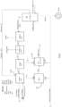
- Fig. 1 gives indicative parameter values which are set out in the table below with notes on where they are, giving an understanding of operation of the system 1.
- Table 1 Part of System 1 Air/Gas/Water Temperature (°C) Ambient air inlet to main conduit 2 7 Air flow from turbine 20 electronic controller waste heat, delivered through the main conduit secondary inlet 5 30 Residual flue gas from third stage 25(c) of heat exchanger ("HX") to secondary inlet 26 of the main conduit 2 18 Flue gas from the turbine 20 into the HX first stage 309 Water into ASHP 50, from HX third stage 20.6 Air into cooler 8, from main conduit 2 12 Air out of main conduit outlet 9 to ambient 4 Process hot water from first stage 25(a) of heat exchanger 90 Process hot water from second stage 25(b) of heat exchanger 60 Water from the ASHP 50 to the WSHP 60 22.4
- HX heat exchanger
- the heat exchanger 25 is a three-stage heat exchanger with low pressure drop on the exhaust gas side, which provides heated process water from stage 25 (a) and 25 (b) at two temperature levels:
- the heat exchangers are comprised of a number of cassettes that are arranged both in series and in parallel to split the total water flows into two streams, thus reducing the flow through each stream, to manage port and channel pressure loss.
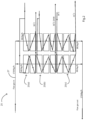
- the heat exchanger 25 is shown in more detail in Fig. 2 .
- Flue gas from the turbine enters via a conduit 27.
- the flue gas enters the first stage 25(a) at for example 309 °C.
- the turbine flue gas is in the primary side of all three stages, the secondary side being water.
- the turbine 20 receives gas fuel which with ambient air, is combusted to drive a turbine which in turn rotates a generator to generate electricity.
- the exhaust gas from the combustion exits after recuperation, at 309°C and is progressively cooled to 18°C in the three-stage water cooled heat exchanger system, HX 25.
- the heating system delivers high temperature heat with greater efficiency than a boiler, and, without additional fuel consumption, will deliver electrical power with no additional environmental costs. This is achieved through the use of ambient air as a heat energy source.
- the system supplies its own controlled energy source for the heat pumps regardless of outside ambient air temperature. It can supply a source temperature 23°C above ambient on to the evaporator 8.
- the ASHP 50 supplies part of the working energy source for the WSHP 60.
- a controller with digital data processors operates the heat pumps to maximise the combined overall efficiency by controlling the source temperature to each heat pump so that the combined heat pump cycle can deliver water at up to 80°C from the WSHP 60as an additional output to process.
- the heat pump capacities are selected so that the total power consumption, including pumps and other parasitic loads, do not exceed the power output of the turbine.
- the controller increases and decreases thermal and electrical outputs depending on ambient air temperature, and uses ambient air to increase output efficiency. It maintains efficiency at very low ambient (about -17°C) by not using mixing ambient air and by pre-heating ambient air to the turbine (Mode 6).
- the system generates electricity for its parasitic requirements on all operating modes, and the operating modes dictate surplus electrical output to process.
- the system uses a three-compartment heat exchanger with three different temperature outputs, and it uses an air-to-air heat reclaim system which is temperature-controlled.
- flue gas temperature is controlled by a temperature sensor Sensor 1 and a pump S-1 by controlling the speed of the pump S-1, the flue temperature having a set point of 94 °C.
- Flue gas temperature is controlled by a temperature sensor Sensor-2 and a pump S-2 by controlling the speed. Flue temperature set point 54°C.
- Flue gas temperature is controlled in response to a temperature feed from a combined temperature and pressure sensor Sensor-3 and a pump S-3 is controlled by controlling the speed. Flue temperature set point is 18°C. All of the pumps S-1, S-2, and S-3 are VSD pumps.
- An anemometer and a temperature sensor Sensor-8 calculate available energy in air flow leaving 25(c), and this will modulate capacity of ASHP, WSHP and flow on pump S-3.
- the sensor Sensor-3 is a combined pressure and temperature sensor.
- the controller is programmed to monitor by way of a feed from Sensor-3 the pressure in the flue gas heat exchanger 25. It is maintained at approximately 15milliBar (mB) by control of the fan 8, and the preferred pressure range for the heat exchanger 25 is 5mB to 20mB. If it rises above the level of 20mB the controller disables the overall system to prevent excessive fuel consumption.
- the fan 7 is varied if the Sensor-3 sensed pressure in the heat exchanger is in the range of 15 to 20mB.
- the turbine is run with a lean mix, in one example 23:77 gas:air ratio.
- Energy is captured from the turbine control electronics and residual flue gas increase the energy in the air flowing through the main conduit 2, from the ambient inlet of 7°C to 12 °C an entry to the evaporator 8.
- Energy from the evaporator 8 coil water energy from the HX third stage boost the inputs to the ASHP and WSHP, greatly increasing their efficiencies.
- the WSHP 60 receives in one example inlet water at greater than 20 °C rather than about 8 °C which is typical.
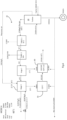
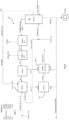
- Figs. 3 to 8 illustrate various modes of operation, set out in detail below. In these examples and in the drawings all flows are per hour. Also, Stage 4 is provided by the main conduit 2, the fan 7, and the cooler 8.
- the system recovers latent heat energy through the condensation of the water vapour in the exhaust gas, without creating excessive back pressure on the turbine, while recovering energy to do useful work. It avoids the problem of a large surface being required to extract latent energy with one heat exchanger as it will cause back pressure on turbine and reduce electrical output, by reducing the volume flow through the heat exchanger. This is achieved by a number (in this example 16) of flue gas heat exchangers in parallel which divides the flow and halves the pressure drop.
- system 1 achieves recovery of low temperature energy and delivery of high temperature energy by split heat recovery in multiple separate compartments and each compartment with its own delivered temperature set point with no temperature cross contamination.
- the system condenses flue gas, despite the fact that in general, condensing will not occur at exhaust gas temperatures greater than 54°C. This is primarily due to the use of a water source heat pump to cool the flue and extract the latent energy and use this energy to increase the efficiency of the WSHP.
- the temperature of the source to the WSHP can be controlled to allow the delivery of higher temperature water from the WSHP, whilst maintaining efficiency.
- the system moreover recovers residual waste heat from the flue gas, waste heat from the electronic circuits and ambient air, and elevates the blended air above the ambient air temperature. This temperature will increase efficiency on to evaporator coil 8 which increases the efficiency of the ASHP, in a controlled manner.
Landscapes
- Engineering & Computer Science (AREA)
- Physics & Mathematics (AREA)
- Thermal Sciences (AREA)
- Chemical & Material Sciences (AREA)
- Combustion & Propulsion (AREA)
- Mechanical Engineering (AREA)
- General Engineering & Computer Science (AREA)
- Air Supply (AREA)
Claims (15)
- Heizsystem (1), das Folgendes aufweist:eine elektronische Steuerung,eine Turbine (20) zum Verbrennen eines Brennstoffs zum Bereitstellen von Abgas und elektrischer Energie,einen Abgaswärmetauscher (25) zum Aufnehmen des Abgases und zum Verwenden des Abgases zum Erwärmen von Wasser,eine Hauptleitung (2) zum Aufnehmen von Einlassluft (3) und Gasen von sekundären Einlässen (5, 26) von innerhalb des Systems zum Erhöhen der Temperatur in der Hauptleitung (2) über die Umgebungstemperatur,einen Luftwärmetauscher (8) zum Rückgewinnen von Wärme aus dem Luftstrom der Hauptleitung undeine Luftquellen-Wärmepumpe ASHP (50) zum Aufnehmen von Energie aus dem Luftwärmetauscher (8),wobeider Luftwärmetauscher einen Kühler (8) aufweist, der zum Kühlen von Luft aus der Hauptleitung (2) zum Entlüften in die Atmosphäre angeordnet ist,dadurch gekennzeichnet, dassder Kühler (8) einen Verdampferschlangenkühler aufweist und sich eine Verdampferschlange mit der ASHP (5) zum Übertragen von Energie an die genannte ASHP teilt,das System ferner eine Wasserquellen-Wärmepumpe WSHP (60) zum Aufnehmen einer Wassereinspeisung mit einer erhöhten Temperatur von der ASHP (50) aufweist, bei dem wenigstens eine Stufe (25(a), 25(b)) des Abgaswärmetauschers und der WSHP zum Bereitstellen von Brauchwarmwasser ausgebildet ist, und wobei zurückgewonnene Energie aus dem Abgaswärmetauscher (25(c)) dem WSHP (60) bereitgestellt wird,wobei der Kühler und die ASHP in einem Verdampferkreislauf sind, wodurch der Kühler (8) Energie an die ASHP (50) liefert, die ASHP Wasser mit erhöhter Temperatur von dem Abgaswärmetauscher (25(c)) aufnimmt und Wasser mit erhöhter Temperatur an die WSHP (60) liefert, und der Abgaswärmetauscher (25) Wasser mit erhöhter Temperatur an die WSHP liefert.
- Heizsystem nach Anspruch 1, wobei der Abgaswärmetauscher (25) Wasser in mehreren Stufen erwärmt, um eine Vielzahl von Warmwasser-Brauchwasserauslässen bereitzustellen.
- Heizsystem nach Anspruch 1 oder Anspruch 2, wobei ein erster sekundärer Einlass (5) der Hauptleitung (2) zum Bereitstellen erwärmter Luft aus Regelkreisen der Turbine eingerichtet ist.
- Heizsystem nach einem der vorhergehenden Ansprüche, wobei ein zweiter sekundärer Einlass (26) der Hauptleitung (2) zum Bereitstellen von Restabgas aus dem Abgaswärmetauscher (25(c)) eingerichtet ist.
- Heizsystem nach einem der vorhergehenden Ansprüche, wobei ein erster sekundärer Einlass (5) der Hauptleitung (2) zum Bereitstellen erwärmter Luft aus Regelkreisen der Turbine eingerichtet ist, ein zweiter sekundärer Einlass (26) der Hauptleitung (2) zum Bereitstellen von Restabgas aus dem Abgaswärmetauscher (25(c)) eingerichtet ist; und wobei der erste sekundäre Einlass zum Bereitstellen von erwärmter Turbinenregelkreis-Luft (5) stromaufwärts des zweiten sekundären Einlasses (26) angeordnet ist.
- Heizsystem nach einem der vorhergehenden Ansprüche, wobei wenigstens eine Stufe des Wärmetauschers (25) mehrere Kreisläufe aufweist, wobei der Stufeneinlassstrom zur Druckminderung geteilt wird.
- Heizsystem nach einem der vorhergehenden Ansprüche, wobei die Steuerung zur Rückgewinnung latenter Wärmeenergie ohne Erzeugen von übermäßigem Gegendruck auf die Turbine (20), während Energie zum Verrichten von Nutzarbeit zurückgewonnen wird, eingerichtet ist, so dass eine Verschlechterung des elektrischen Wirkungsgrads der Turbine vermieden wird, und wobei die Steuerung zum Bereitstellen von Kondensation von Wasserdampf im Abgas im Abgaswärmetauscher (25) durch die WSHP (60) eingerichtet ist, die das Abgas kühlt und latente Energie extrahiert, um den Wirkungsgrad der WSHP zu erhöhen, wobei der Wasserdampf im Abgas die Verbrennungsprodukte und den Wasserdampf in der einströmenden Umgebungsluft zur Verbrennung beinhaltet.
- Heizsystem nach einem der vorhergehenden Ansprüche, wobei die Steuerung zum Veranlassen der Turbine zum Verwenden eines hohen Luft-Brennstoff-Verhältnisses von mehr als 30 Gew.-% Luft, wodurch aus der nachfolgenden Kondensation verfügbare Wärme gewonnen wird, eingerichtet ist.
- Heizsystem nach einem der vorhergehenden Ansprüche, wobei die Hauptleitung ein Auslassgebläse (7) aufweist und die Steuerung zum Steuern des genannten Gebläses zum Regeln des Drucks im Abgaswärmetauscher, um übermäßigen Brennstoffverbrauch zu verhindern, ausgebildet ist und wahlweise der Druck im Abgaswärmetauscher im Bereich von 5 mB bis 20 mB gehalten wird.
- Verfahren zum Betreiben eines Heizsystems (1), das Folgendes aufweist:eine elektronische Steuerung,eine Turbine (20),einen Abgaswärmetauscher (25), der mehrere Stufen aufweist und mit einer Hauptleitung verbunden ist, die wenigstens einen sekundären Einlass hat,einen Luftwärmetauscher (8) in der genannten Hauptleitung undeine Luftquellen-Wärmepumpe ASHP (50),dadurch gekennzeichnet, dassder Luftwärmetauscher einen Kühler (8) aufweist, der zum Kühlen von Luft aus der Hauptleitung (2) zum Entlüften in die Atmosphäre angeordnet ist,der Kühler (8) einen Verdampferschlangenkühler aufweist und sich eine Verdampferschlange mit der ASHP (5) zum Übertragen von Energie an die genannte ASHP teilt,das System ferner eine Wasserquellen-Wärmepumpe WSHP (60) zum Aufnehmen einer Wassereinspeisung mit einer erhöhten Temperatur von der ASHP (50) aufweist, bei dem wenigstens eine Stufe (25(a), 25(b)) des Abgaswärmetauschers und der WSHP zum Bereitstellen von Brauchwarmwasser ausgebildet ist, und wobei zurückgewonnene Energie aus dem Abgaswärmetauscher (25(c)) dem WSHP (60) bereitgestellt wird,wobei der Kühler und die ASHP in einem Verdampferkreislauf sind,wobei das Verfahren die folgenden Schritte aufweist:durch die Turbine Verbrennen eines Brennstoffs zum Bereitstellen von Abgas und elektrischer Energie,durch den Abgaswärmetauscher (25) Aufnehmen des Abgases und Verwenden des Abgases zum Erwärmen von Wasser,durch die Hauptleitung (2) Aufnehmen von Einlassluft (3) und Gasen von sekundären Einlässen (5, 26) innerhalb des Systems zum Erhöhen der Temperatur in der Hauptleitung (2) über die Umgebungstemperatur unddurch den Luftwärmetauscher (8) Rückgewinnen von Wärme aus dem Luftstrom der Hauptleitung unddurch die Luftquellen-Wärmepumpe ASHP (50) Aufnehmen von Energie aus dem Luftwärmetauscher (8),durch den Kühler (8) Liefern von Energie an die ASHP (50),durch die ASHP Aufnehmen von Wasser mit erhöhter Temperatur von dem Abgaswärmetauscher (25(c)) und Liefern von Wasser mit erhöhter Temperatur an die WSHP (60),durch den Abgaswärmetauscher (25) Liefern von Wasser mit erhöhter Temperatur an die WSHP unddurch die WSHP Aufnehmen einer Wassereinspeisung mit einer erhöhten Temperatur von der ASHP (50), bei dem wenigstens eine Stufe (25(a), 25(b)) des Abgaswärmetauschers und der WSHP Brauchwarmwasser bereitstellt.
- Verfahren nach Anspruch 10, wobei der Abgaswärmetauscher (25) Wasser in den mehreren Stufen erwärmt, um eine Vielzahl von Warmwasser-Brauchwasserauslässen bereitzustellen.
- Verfahren nach einem der Ansprüche 10 oder 11, wobei das System einen ersten sekundären Einlass (5) der Hauptleitung (2) aufweist und der genannte Einlass erwärmte Luft aus Regelkreisen der Turbine bereitstellt.
- Verfahren nach einem der Ansprüche 10 bis 12, wobei das System einen zweiten sekundären Einlass (26) der Hauptleitung (2) aufweist und der genannte Einlass Restabgas aus dem Abgaswärmetauscher (25(c)) bereitstellt.
- Verfahren nach Anspruch 13, wobei der erste sekundäre Einlass (5) erwärmte Luft aus Regelkreisen der Turbine bereitstellt, der zweite sekundäre Einlass (26) Restabgas aus dem Abgaswärmetauscher (25(c)) bereitstellt; und der erste sekundäre Einlass erwärmte Turbinenregelkreis-Luft (5) stromaufwärts des zweiten sekundären Einlasses (26) bereitstellt.
- Verfahren nach einem der Ansprüche 10 bis 14, wobei wenigstens eine Stufe des Wärmetauschers (25) mehrere Kreisläufe aufweist und das Verfahren das Teilen des Stufeneinlassstroms zur Druckminderung aufweist und das Verfahren das Rückgewinnen latenter Wärmeenergie ohne Erzeugen von übermäßigem Gegendruck auf die Turbine (20) beinhaltet, während Energie zum Verrichten von Nutzarbeit zurückgewonnen wird, so dass eine Verschlechterung des elektrischen Wirkungsgrads der Turbine vermieden wird.
Applications Claiming Priority (2)
| Application Number | Priority Date | Filing Date | Title |
|---|---|---|---|
| EP20188397 | 2020-07-29 | ||
| PCT/EP2021/070024 WO2022023086A1 (en) | 2020-07-29 | 2021-07-16 | A heating system |
Publications (3)
| Publication Number | Publication Date |
|---|---|
| EP4189303A1 EP4189303A1 (de) | 2023-06-07 |
| EP4189303B1 true EP4189303B1 (de) | 2024-09-11 |
| EP4189303C0 EP4189303C0 (de) | 2024-09-11 |
Family
ID=71846293
Family Applications (1)
| Application Number | Title | Priority Date | Filing Date |
|---|---|---|---|
| EP21742432.4A Active EP4189303B1 (de) | 2020-07-29 | 2021-07-16 | Heizsystem |
Country Status (3)
| Country | Link |
|---|---|
| US (1) | US20230266019A1 (de) |
| EP (1) | EP4189303B1 (de) |
| WO (1) | WO2022023086A1 (de) |
Families Citing this family (1)
| Publication number | Priority date | Publication date | Assignee | Title |
|---|---|---|---|---|
| US20240318878A1 (en) * | 2023-03-21 | 2024-09-26 | Venaera Inc. | Control System And Air Source Heat Pump |
Family Cites Families (10)
| Publication number | Priority date | Publication date | Assignee | Title |
|---|---|---|---|---|
| GB605954A (en) * | 1944-10-12 | 1948-08-04 | Spladis Soc Pour L Applic D In | Improved solid-fuel fired instantaneous steam boilers for locomotives |
| DE3002387A1 (de) * | 1980-01-24 | 1981-08-20 | Karl Schaeff GmbH & Co, Maschinenfabrik, 7183 Langenburg | Verfahren zur verbesserten waermerueckgewinnung in einem bi- oder mehrvalenten warmwasser-heizugssystem |
| DE29708140U1 (de) * | 1997-05-06 | 1997-07-10 | Höfer, Hendrik, 53604 Bad Honnef | Wärmeaustauschende Vorrichtung für heiße Abgase von Feuerungsanlagen |
| CH701785A1 (de) * | 2009-09-07 | 2011-03-15 | Walter Schmid | Anlage zur Bereitstellung von Wärmeenergie. |
| CN102906506B (zh) * | 2009-12-08 | 2016-08-03 | 电动能源公司 | 热和电的分配以及热电联产的方法及系统 |
| DE102014206474A1 (de) * | 2013-04-05 | 2014-10-09 | Dürr Systems GmbH | Anlage zum Bereitstellen von Wärmeenergie für Wärmeverbraucher |
| US10927713B2 (en) * | 2015-03-17 | 2021-02-23 | Mitsubishi Heavy Industries, Ltd. | Intake air cooling method, intake air cooling device executing said method, and waste heat recovery facility and gas turbine plant each comprising said intake air cooling device |
| CH712260B1 (de) * | 2016-09-12 | 2017-09-29 | W Schmid Projekte Ag | Anlage zur Bereitstellung von Wärmeenergie und elektrischem Strom. |
| SE542257C2 (en) * | 2016-09-26 | 2020-03-24 | Clean Bio Heat Sverige Ab | Flue gas treatment system and method |
| WO2020196654A1 (ja) * | 2019-03-27 | 2020-10-01 | ダイキン工業株式会社 | 給湯装置 |
-
2021
- 2021-07-16 US US18/017,973 patent/US20230266019A1/en active Pending
- 2021-07-16 EP EP21742432.4A patent/EP4189303B1/de active Active
- 2021-07-16 WO PCT/EP2021/070024 patent/WO2022023086A1/en not_active Ceased
Also Published As
| Publication number | Publication date |
|---|---|
| WO2022023086A1 (en) | 2022-02-03 |
| EP4189303C0 (de) | 2024-09-11 |
| EP4189303A1 (de) | 2023-06-07 |
| US20230266019A1 (en) | 2023-08-24 |
Similar Documents
| Publication | Publication Date | Title |
|---|---|---|
| US9926813B2 (en) | Heat energy distribution systems and methods for power recovery | |
| US8424282B2 (en) | Combined-cycle power plant with exhaust gas recycling and CO2 separation, and method for operating a combined cycle power plant | |
| DK3201532T3 (en) | METHOD AND DEVICE FOR UTILIZATION OF WASTE HEAT FROM CHANGE HEATERS BY INCORPORATED HIGH TEMPERATURE HEAT PUMP WITH WATER SOURCE | |
| US20110239650A1 (en) | Power plant comprising a turbine unit and a generator | |
| GB2036879A (en) | Gas turbine steam turbine combination set | |
| CN108431376B (zh) | 热力循环和热源的功能协同效应 | |
| US4287723A (en) | Central heating and/or sanitary or industrial hot-water production installation | |
| EP3869599B1 (de) | Umkehrbares wasserelektrolysesystem und verfahren zum betrieb davon | |
| JP2018533712A (ja) | 組み込み高温水源ヒートポンプによる給湯装置廃熱回収の利用方法及び設備 | |
| CN106996571A (zh) | 一种燃煤热水锅炉烟气余热深度回收系统及其方法 | |
| EP4189303B1 (de) | Heizsystem | |
| CN108678931B (zh) | 一种压气机抽气储能提高冷热电联产系统灵活性的方法 | |
| EP1628091A2 (de) | Klimaanlage kombiniert mit einem elektrizitäterzeugungsystem | |
| NL8201397A (nl) | Inrichting voor het benutten van afvalwarmte met lage energie van een compressorstation in een gaspijpleiding. | |
| CN103335445A (zh) | 燃气驱动压缩机余热利用系统及方法 | |
| CN100449218C (zh) | 用于能量回收的方法和装置 | |
| EP3296658A1 (de) | Abluftwärmepumpenvorrichtung und verfahren zur verarbeitung von abluft | |
| CN108140917A (zh) | 电池预热系统 | |
| GB2351323A (en) | Heat and power generation plant. | |
| CN107842874A (zh) | 一种一、二次风热量分配调节系统及方法 | |
| SE523716C2 (sv) | Klimatanläggning | |
| CN105822427A (zh) | 回热循环燃气轮机系统及冷热电联供系统 | |
| EP3242081B1 (de) | Optimierung einer gasbefeuerten strahlrohrheizvorrichtung | |
| KR20230094626A (ko) | 가열로 배열회수 장치 및 방법 | |
| KR101919696B1 (ko) | 복합 사이클 발전 플랜트 |
Legal Events
| Date | Code | Title | Description |
|---|---|---|---|
| STAA | Information on the status of an ep patent application or granted ep patent |
Free format text: STATUS: UNKNOWN |
|
| STAA | Information on the status of an ep patent application or granted ep patent |
Free format text: STATUS: THE INTERNATIONAL PUBLICATION HAS BEEN MADE |
|
| PUAI | Public reference made under article 153(3) epc to a published international application that has entered the european phase |
Free format text: ORIGINAL CODE: 0009012 |
|
| STAA | Information on the status of an ep patent application or granted ep patent |
Free format text: STATUS: REQUEST FOR EXAMINATION WAS MADE |
|
| 17P | Request for examination filed |
Effective date: 20230207 |
|
| AK | Designated contracting states |
Kind code of ref document: A1 Designated state(s): AL AT BE BG CH CY CZ DE DK EE ES FI FR GB GR HR HU IE IS IT LI LT LU LV MC MK MT NL NO PL PT RO RS SE SI SK SM TR |
|
| DAV | Request for validation of the european patent (deleted) | ||
| DAX | Request for extension of the european patent (deleted) | ||
| GRAP | Despatch of communication of intention to grant a patent |
Free format text: ORIGINAL CODE: EPIDOSNIGR1 |
|
| STAA | Information on the status of an ep patent application or granted ep patent |
Free format text: STATUS: GRANT OF PATENT IS INTENDED |
|
| INTG | Intention to grant announced |
Effective date: 20240415 |
|
| RIN1 | Information on inventor provided before grant (corrected) |
Inventor name: O'LEARY, JOHN Inventor name: FLYNN, LIAM |
|
| GRAS | Grant fee paid |
Free format text: ORIGINAL CODE: EPIDOSNIGR3 |
|
| GRAA | (expected) grant |
Free format text: ORIGINAL CODE: 0009210 |
|
| STAA | Information on the status of an ep patent application or granted ep patent |
Free format text: STATUS: THE PATENT HAS BEEN GRANTED |
|
| AK | Designated contracting states |
Kind code of ref document: B1 Designated state(s): AL AT BE BG CH CY CZ DE DK EE ES FI FR GB GR HR HU IE IS IT LI LT LU LV MC MK MT NL NO PL PT RO RS SE SI SK SM TR |
|
| REG | Reference to a national code |
Ref country code: GB Ref legal event code: FG4D |
|
| REG | Reference to a national code |
Ref country code: CH Ref legal event code: EP |
|
| REG | Reference to a national code |
Ref country code: DE Ref legal event code: R096 Ref document number: 602021018693 Country of ref document: DE |
|
| REG | Reference to a national code |
Ref country code: IE Ref legal event code: FG4D |
|
| U01 | Request for unitary effect filed |
Effective date: 20240923 |
|
| RAP4 | Party data changed (patent owner data changed or rights of a patent transferred) |
Owner name: ACTIONZERO ESCOPOD LIMITED |
|
| U07 | Unitary effect registered |
Designated state(s): AT BE BG DE DK EE FI FR IT LT LU LV MT NL PT RO SE SI Effective date: 20241017 |
|
| PG25 | Lapsed in a contracting state [announced via postgrant information from national office to epo] |
Ref country code: NO Free format text: LAPSE BECAUSE OF FAILURE TO SUBMIT A TRANSLATION OF THE DESCRIPTION OR TO PAY THE FEE WITHIN THE PRESCRIBED TIME-LIMIT Effective date: 20241211 |
|
| PG25 | Lapsed in a contracting state [announced via postgrant information from national office to epo] |
Ref country code: GR Free format text: LAPSE BECAUSE OF FAILURE TO SUBMIT A TRANSLATION OF THE DESCRIPTION OR TO PAY THE FEE WITHIN THE PRESCRIBED TIME-LIMIT Effective date: 20241212 |
|
| PG25 | Lapsed in a contracting state [announced via postgrant information from national office to epo] |
Ref country code: HR Free format text: LAPSE BECAUSE OF FAILURE TO SUBMIT A TRANSLATION OF THE DESCRIPTION OR TO PAY THE FEE WITHIN THE PRESCRIBED TIME-LIMIT Effective date: 20240911 |
|
| PG25 | Lapsed in a contracting state [announced via postgrant information from national office to epo] |
Ref country code: ES Free format text: LAPSE BECAUSE OF FAILURE TO SUBMIT A TRANSLATION OF THE DESCRIPTION OR TO PAY THE FEE WITHIN THE PRESCRIBED TIME-LIMIT Effective date: 20240911 Ref country code: RS Free format text: LAPSE BECAUSE OF FAILURE TO SUBMIT A TRANSLATION OF THE DESCRIPTION OR TO PAY THE FEE WITHIN THE PRESCRIBED TIME-LIMIT Effective date: 20241211 |
|
| PG25 | Lapsed in a contracting state [announced via postgrant information from national office to epo] |
Ref country code: RS Free format text: LAPSE BECAUSE OF FAILURE TO SUBMIT A TRANSLATION OF THE DESCRIPTION OR TO PAY THE FEE WITHIN THE PRESCRIBED TIME-LIMIT Effective date: 20241211 Ref country code: NO Free format text: LAPSE BECAUSE OF FAILURE TO SUBMIT A TRANSLATION OF THE DESCRIPTION OR TO PAY THE FEE WITHIN THE PRESCRIBED TIME-LIMIT Effective date: 20241211 Ref country code: HR Free format text: LAPSE BECAUSE OF FAILURE TO SUBMIT A TRANSLATION OF THE DESCRIPTION OR TO PAY THE FEE WITHIN THE PRESCRIBED TIME-LIMIT Effective date: 20240911 Ref country code: GR Free format text: LAPSE BECAUSE OF FAILURE TO SUBMIT A TRANSLATION OF THE DESCRIPTION OR TO PAY THE FEE WITHIN THE PRESCRIBED TIME-LIMIT Effective date: 20241212 Ref country code: ES Free format text: LAPSE BECAUSE OF FAILURE TO SUBMIT A TRANSLATION OF THE DESCRIPTION OR TO PAY THE FEE WITHIN THE PRESCRIBED TIME-LIMIT Effective date: 20240911 |
|
| PG25 | Lapsed in a contracting state [announced via postgrant information from national office to epo] |
Ref country code: IS Free format text: LAPSE BECAUSE OF FAILURE TO SUBMIT A TRANSLATION OF THE DESCRIPTION OR TO PAY THE FEE WITHIN THE PRESCRIBED TIME-LIMIT Effective date: 20250111 |
|
| PG25 | Lapsed in a contracting state [announced via postgrant information from national office to epo] |
Ref country code: SM Free format text: LAPSE BECAUSE OF FAILURE TO SUBMIT A TRANSLATION OF THE DESCRIPTION OR TO PAY THE FEE WITHIN THE PRESCRIBED TIME-LIMIT Effective date: 20240911 |
|
| PG25 | Lapsed in a contracting state [announced via postgrant information from national office to epo] |
Ref country code: CZ Free format text: LAPSE BECAUSE OF FAILURE TO SUBMIT A TRANSLATION OF THE DESCRIPTION OR TO PAY THE FEE WITHIN THE PRESCRIBED TIME-LIMIT Effective date: 20240911 Ref country code: PL Free format text: LAPSE BECAUSE OF FAILURE TO SUBMIT A TRANSLATION OF THE DESCRIPTION OR TO PAY THE FEE WITHIN THE PRESCRIBED TIME-LIMIT Effective date: 20240911 |
|
| PG25 | Lapsed in a contracting state [announced via postgrant information from national office to epo] |
Ref country code: SK Free format text: LAPSE BECAUSE OF FAILURE TO SUBMIT A TRANSLATION OF THE DESCRIPTION OR TO PAY THE FEE WITHIN THE PRESCRIBED TIME-LIMIT Effective date: 20240911 |
|
| PLBE | No opposition filed within time limit |
Free format text: ORIGINAL CODE: 0009261 |
|
| STAA | Information on the status of an ep patent application or granted ep patent |
Free format text: STATUS: NO OPPOSITION FILED WITHIN TIME LIMIT |
|
| 26N | No opposition filed |
Effective date: 20250612 |
|
| REG | Reference to a national code |
Ref country code: CH Ref legal event code: H13 Free format text: ST27 STATUS EVENT CODE: U-0-0-H10-H13 (AS PROVIDED BY THE NATIONAL OFFICE) Effective date: 20260224 |
|
| GBPC | Gb: european patent ceased through non-payment of renewal fee |
Effective date: 20250716 |
|
| U90 | Renewal fees not paid: noting of loss of rights |
Free format text: RENEWAL FEE NOT PAID FOR YEAR 05 Effective date: 20260223 |
|
| PG25 | Lapsed in a contracting state [announced via postgrant information from national office to epo] |
Ref country code: GB Free format text: LAPSE BECAUSE OF NON-PAYMENT OF DUE FEES Effective date: 20250716 |
|
| PG25 | Lapsed in a contracting state [announced via postgrant information from national office to epo] |
Ref country code: CH Free format text: LAPSE BECAUSE OF NON-PAYMENT OF DUE FEES Effective date: 20250731 |