EP4189351B1 - Pièce dotée d'un dispositif de détection intégré pour une mesure optique, sur plusieurs axes, d'une force appliquée - Google Patents
Pièce dotée d'un dispositif de détection intégré pour une mesure optique, sur plusieurs axes, d'une force appliquée Download PDFInfo
- Publication number
- EP4189351B1 EP4189351B1 EP21752045.1A EP21752045A EP4189351B1 EP 4189351 B1 EP4189351 B1 EP 4189351B1 EP 21752045 A EP21752045 A EP 21752045A EP 4189351 B1 EP4189351 B1 EP 4189351B1
- Authority
- EP
- European Patent Office
- Prior art keywords
- component
- optical elements
- support element
- optical
- cavity
- Prior art date
- Legal status (The legal status is an assumption and is not a legal conclusion. Google has not performed a legal analysis and makes no representation as to the accuracy of the status listed.)
- Active
Links
Images



Classifications
-
- G—PHYSICS
- G01—MEASURING; TESTING
- G01L—MEASURING FORCE, STRESS, TORQUE, WORK, MECHANICAL POWER, MECHANICAL EFFICIENCY, OR FLUID PRESSURE
- G01L1/00—Measuring force or stress, in general
- G01L1/24—Measuring force or stress, in general by measuring variations of optical properties of material when it is stressed, e.g. by photoelastic stress analysis using infrared, visible light, ultraviolet
-
- G—PHYSICS
- G01—MEASURING; TESTING
- G01L—MEASURING FORCE, STRESS, TORQUE, WORK, MECHANICAL POWER, MECHANICAL EFFICIENCY, OR FLUID PRESSURE
- G01L1/00—Measuring force or stress, in general
- G01L1/24—Measuring force or stress, in general by measuring variations of optical properties of material when it is stressed, e.g. by photoelastic stress analysis using infrared, visible light, ultraviolet
- G01L1/241—Measuring force or stress, in general by measuring variations of optical properties of material when it is stressed, e.g. by photoelastic stress analysis using infrared, visible light, ultraviolet by photoelastic stress analysis
-
- G—PHYSICS
- G01—MEASURING; TESTING
- G01L—MEASURING FORCE, STRESS, TORQUE, WORK, MECHANICAL POWER, MECHANICAL EFFICIENCY, OR FLUID PRESSURE
- G01L3/00—Measuring torque, work, mechanical power, or mechanical efficiency, in general
- G01L3/02—Rotary-transmission dynamometers
- G01L3/04—Rotary-transmission dynamometers wherein the torque-transmitting element comprises a torsionally-flexible shaft
- G01L3/10—Rotary-transmission dynamometers wherein the torque-transmitting element comprises a torsionally-flexible shaft involving electric or magnetic means for indicating
- G01L3/12—Rotary-transmission dynamometers wherein the torque-transmitting element comprises a torsionally-flexible shaft involving electric or magnetic means for indicating involving photoelectric means
-
- G—PHYSICS
- G01—MEASURING; TESTING
- G01L—MEASURING FORCE, STRESS, TORQUE, WORK, MECHANICAL POWER, MECHANICAL EFFICIENCY, OR FLUID PRESSURE
- G01L3/00—Measuring torque, work, mechanical power, or mechanical efficiency, in general
- G01L3/02—Rotary-transmission dynamometers
- G01L3/14—Rotary-transmission dynamometers wherein the torque-transmitting element is other than a torsionally-flexible shaft
- G01L3/1407—Rotary-transmission dynamometers wherein the torque-transmitting element is other than a torsionally-flexible shaft involving springs
- G01L3/1421—Rotary-transmission dynamometers wherein the torque-transmitting element is other than a torsionally-flexible shaft involving springs using optical transducers
-
- G—PHYSICS
- G01—MEASURING; TESTING
- G01L—MEASURING FORCE, STRESS, TORQUE, WORK, MECHANICAL POWER, MECHANICAL EFFICIENCY, OR FLUID PRESSURE
- G01L5/00—Apparatus for, or methods of, measuring force, work, mechanical power, or torque, specially adapted for specific purposes
- G01L5/16—Apparatus for, or methods of, measuring force, work, mechanical power, or torque, specially adapted for specific purposes for measuring several components of force
- G01L5/166—Apparatus for, or methods of, measuring force, work, mechanical power, or torque, specially adapted for specific purposes for measuring several components of force using photoelectric means
-
- G—PHYSICS
- G01—MEASURING; TESTING
- G01L—MEASURING FORCE, STRESS, TORQUE, WORK, MECHANICAL POWER, MECHANICAL EFFICIENCY, OR FLUID PRESSURE
- G01L5/00—Apparatus for, or methods of, measuring force, work, mechanical power, or torque, specially adapted for specific purposes
- G01L5/24—Apparatus for, or methods of, measuring force, work, mechanical power, or torque, specially adapted for specific purposes for determining value of torque or twisting moment for tightening a nut or other member which is similarly stressed
Definitions
- the present invention relates to a component with an integrated sensor device for an optical, multi-axis measurement of a force acting on the component, a method for producing such a component with an integrated sensor device, and in particular to a structure-integrated optical multi-axis force/torque measurement.
- Sensor devices integrated into a component are known for measuring the force acting on a component or part of a structure.
- the sensors use piezo actuators or strain gauges to detect loads and their direction of action. Strain gauges or piezoelectric sensors are also used, for example, in a WO 2016 177 356 A1
- the sensor unit disclosed and integrated into a hollow shaft is used to determine mechanical stress on the hollow shaft.
- Sensor devices based on optical devices and detecting forces in multiple axes are also known.
- the document WO 2013 072 712 A1 a light source arranged on a support element under a hemispherical cover layer and a light detector, which are designed to detect a deformation of the cover layer due to light reflection therefrom.
- sensor units based on interferometry are known, such as the interferometer from the document DE 41 32 110 A1 which is embedded in an elastically deformable body.
- optical sensors for multi-axis force measurements are known.
- the published patent application US 2013/0265233 A1 an optical measuring device for multi-axis input devices with several mutually movable parts.
- the font US 2019/0072443 A1 discloses an optical measuring device for a robot, which is designed to determine a displacement of an inner element relative to an outer element connected to it by flexible elements in several axes.
- the document DE 10 2017 101 580 A1 a laser interferometer, which can measure even a small parallel offset of the reflected laser beam and thus determine displacements of an object to be measured.
- the present invention relates to a component with an integrated sensor device for optical, multi-axis measurement of a force (a force or a torque) acting on the component.
- the component has a cavity in which a first support element with one or more first optical elements and a second support element with one or more second optical elements are formed and partially inserted into the component.
- the portions of the first and second support elements joined into a material of the component fix the support elements to the component.
- the support elements can be fixed, for example, by soldering, gluing, welding, or screwing; however, these joining methods are not sufficiently secure and are only suitable to a limited extent for the high demands of the sensor device for a precise, backlash-free, and long-term stable connection to the component.
- the fixing of the support elements is advantageously carried out by cold forging or a Cold forming of the support elements and/or the component takes place.
- the component further comprises a transmission device which is designed to be connected to an energy source and, when connected to the energy source, to transmit or generate at least two beams in mutually independent directions, wherein the beams each run between the first optical elements and the second optical elements through the cavity.
- the first optical elements and the second optical elements are designed to generate information about a relative position change of the first support element with respect to the second support element based on the at least two beams.
- the transmission device is also designed to provide the information for measuring the force effect or to transmit the information out of the component, wherein the second optical elements have a mirror and the at least two beams have a reflected beam and an unreflected beam.
- a relative position change between the first and second support elements occurs due to the joining connection of the first and second support elements to the component when an external force or torque acts on the component and deforms it due to the elasticity of the component.
- the two beams are advantageously part of a beam path that is suitable for providing information about the position change even in the event of minor deformations of the component due to external force.
- the independent directions of the at least two beams allow measurement of the position change or the force effect with respect to multiple axes or directions.
- the first and second optical elements can be configured to superimpose the at least two beams to form a collected beam, and the transmission device can be configured to transmit the collected beam out of the structure.
- a pixel-based detection of a displacement such as digital image correlation or a digital moiré method
- at least one of the beams can pass between partially reflecting plates (or semi-transparent mirrors), thus forming a Fabry-Pérot interferometer.
- at least one of the beams can also be part of a beam path of a Michelson interferometer.
- the transmission device is designed to be connected to a light source as an energy source.
- the light source can, in particular, be a laser device.
- the connection can be implemented by coupling a laser beam into a light guide, such as a fiber optic cable, which is designed to guide the laser beam to the first and/or second optical elements and thus generate a beam path between the optical elements that comprises the at least two beams.
- the transmission device can also be designed to be connected to a power source as an energy source.
- a power cable can conduct power to one or more of the first and/or second optical elements, which are designed to generate a beam path that comprises the at least two beams.
- the transmission device can further be designed to transmit the information about the relative position change of the first support element with respect to the second support element out of the component via a light guide.
- a fiber optic cable can again be provided for this purpose.
- the transmission device can also be designed to transmit the information out of the component via an electrical line.
- a superposition of the beams can be converted into an electrical signal by optical elements such as diodes, semiconductor components or cameras, which transmits the information through the electrical line.
- the component is one of the following: a hollow shaft, a hollow cylindrical component, a pipe, a robot element (in particular a robot arm), an element intended for a structure, a crane or load arm, a connecting element, a column of a machine tool, a tool, a tool holder.
- the first optical elements and/or the second optical elements comprise an optical pattern and are configured to superimpose the at least two beams, so that the information comprises a change in a captured optical image of the optical pattern.
- the change in the optical image of this pattern can be achieved, in particular, by a displacement of the optical pattern.
- masks can be attached in the path of the two beams, each having openings as an optical pattern, so that the beams transmit an image of the optical pattern.
- the change in the image then results, for example, from a relative displacement and/or rotation of the openings, triggered by the relative change in position of the support elements.
- the change in the image can be determined in particular from the superimposed beams using a pixel-based method.
- the pixel-based method can be, for example, digital image correlation or a method in which a displacement of a moiré pattern is measured.
- the first optical elements and the second optical elements form a Michelson interferometer for at least one of the at least two beams.
- a Michelson interference pattern that is used to generate the information about the relative position change or that represents this information.
- At least one first optical element and at least one second optical element each comprise a partially reflecting plate and are configured to form a Fabry-Pérot interferometer for at least one of the at least two beams.
- At least one further support element with one or more further optical elements is formed in the cavity and partially inserted into the component, so that the at least one further support element is correspondingly included in the beam path and the information also allows conclusions to be drawn about a relative change in position with respect to the additional support element(s).
- Embodiments also relate to a method for producing a component according to claim 1 with an integrated sensor device for optical, multi-axis measurement of a force acting on the component.
- the component comprises a cavity, a first support element with first optical elements and at least one further support element with further optical Elements.
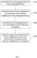
- the method comprises the steps of providing a starting component with a starting cavity; positioning the first support element and the at least one further support element in the starting cavity of the starting component; forming the starting component to form the component and the cavity; and thereby plastically joining the first support element and the at least one further support element to fix the first support element and the second support element in the cavity.
- the forming process presented here as a preferred embodiment can, in particular, be cold bulk forming or cold forming.
- the forming process fixes the first and at least one further support element to the boundary of the cavity. The following two embodiments of the process can be used for this purpose.
- At least one of the support elements comprises a core made of very hard material and has an edge region comprising a material that is more easily deformable than the material of the core. The more easily deformable material is plastically deformed by the forming of the component, so that the at least one support element is fixed in the resulting cavity.
- At least one of the support elements comprises a very hard material compared to a material of the starting component, so that during forming, the starting component is plastically deformed by the hard material of the at least one support element.
- the support element is thus fixed in the cavity of the component created by the forming process.
- Both embodiments can also be combined, i.e. different support elements can be fixed by different embodiments.
- the first support element can be inserted first, before the at least one additional support element is positioned.
- the sensor device can be coupled or operated during positioning and/or during the forming process.
- Embodiments of the present component with an integrated sensor device are thus characterized in that at least two support elements are fixed within an at least partially hollow structure of the component, to which optical elements such as optical fibers, mirrors, light sources, optical markers, and cameras are attached.
- the optical elements are positioned relative to one another such that a relative displacement or rotation of the support elements relative to one another causes, for example, a change in a pattern captured by an internal camera or an external camera connected via an optical fiber. This change in the pattern can be attributed to the existing deformation via image analysis.
- Embodiments implement various beam paths, each comprising rays in different directions or in inclined planes.
- the support elements are advantageously integrated into the structure of the component by (partial) plastic joining.
- the support elements each comprise, at least in one part, a high-strength and rigid material to which the optical elements can also be attached.
- the strength or hardness of the material is greater than that of a cavity wall of the component structure, so that the support elements can be inserted by forming the component.
- the supporting elements can also have a softer material, particularly in an edge region, which ensures that the arrangement of the supporting elements is maintained during the forming process.
- a supporting element can have a very hard core and a comparatively more easily deformable edge region.
- the evaluation in the pixel-based methods can be carried out either by digital image correlation or by digital moiré methods (superposition of line patterns). These pixel-based methods can, in particular, determine parallel displacements between two support elements in all six degrees of freedom. Distance displacements can also be measured.
- the sensor device can, however, also be implemented in a similar way, for example, for a Fabry-Pérot and/or a Michelson interferometry method.
- a change in the distance between the supporting elements can also be measured using an obliquely mounted interferometer and suitable beam guidance (using mirrors). Combinations of different measurement methods for different beams are also possible.
- measurement chains based on changes in electrical properties are largely standardized.
- additional electrical elements such as charge amplifiers or bridge circuits. They also require electrical power supply, and the complexity increases significantly, especially when measuring forces or torques across multiple axes.
- Some conventional measurement chains also use preloaded structures or sensor devices, which can be disadvantageous in some applications.
- inventions of the present invention offer the following advantages.
- the component with an integrated sensor device expands the measuring axes through cost-effective components (particularly when using pixel-based methods) and a suitable arrangement of the beam paths, as well as through an integral design consisting of optical elements and support structures. It also opens up the possibility of scaling the sensors and thus of manufacturing sensor structures in small dimensions.
- the integral design is achieved in particular through plastic joining. This results in a compact design of the component with an integrated sensor device for multi-axial detection of forces and/or torques acting on the component.
- the use of pixel-based methods in particular can result in significant cost savings compared to conventional strain gauge and piezo-based sensors.
- Fig. 1 illustrates an embodiment of the present invention for a component 100 with an integrated sensor device 200 for an optical, multi-axis measurement of a force F and/or a torque M on the component 100.
- the component 100 has a cavity 110 with a wall 120.
- the sensor device 200 comprises a first support element 210 with a plurality of first optical elements 220.
- the first optical elements 220 comprise, in particular, two beam expansion elements 221, which are designed to expand light supplied from an energy source via a light guide and to guide it as beams 331, 332 into the cavity 110 through an optical pattern 222 or a back-illuminated photomask.
- the sensor device 200 further comprises a second support element 230 with a plurality of second optical elements 240.
- the second optical elements 240 comprise a mirror 245 and a beam collection element 243, which is designed to collect or superimpose the two beams 331, 332 and to transmit them as a light signal through a line 320, in this case, for example, a fiber optic cable.
- the first support element 210 and the second support element 230 are formed in the cavity 110 and partially inserted into the component 100.
- the component 100 comprises a transmission device 300, which is designed to be connected to an energy source—here, for example, a laser device—and to generate the two beams 331, 332 upon connection to the energy source.
- the two Beams 331, 332 extend in mutually independent directions between the first optical elements 220 and the second optical elements 240 through the cavity 110.
- the first optical elements 220 and the second optical elements 240 are configured to generate, based on the two beams 331, 332, information about a relative position change of the first support element 210 with respect to the second support element 230. In the present embodiment, this is achieved by superposition in the beam collection element 243.
- the transmission device 300 is configured to provide the information for measuring the force F and/or the torque M, or to transmit this information out of the component 100. Due to the independent directions of the beams 331, 332, the measurement is performed with respect to several axes, which are determined by the directions of the beams 331, 332 in the cavity 110: The force F or the torque M shifts a position of the first support element 210 relative to a position of the second support element 230.
- the transmission device 300 can also be designed to supply a supply voltage to the optical elements 220, 240 or to output images from the component 100 instead of light.
- Light-emitting diodes can then be used instead of or in addition to the beam expansion elements 221 to generate the beams (331, 332).
- the beam collection element 243 can be designed as a camera. Mixed forms of this embodiment (for example, with a voltage supply for the first optical elements 220 and a light guide for transmitting the information, or vice versa) are possible.
- Fig. 2 illustrates a further embodiment of the component 100 with integrated sensor device 200.
- the first optical elements 220 generate two beams 331, 332 in independent directions, but here comprise a partially reflecting plate 227 for each of the beams 331, 332.
- a further partially reflecting plate 247 is located in front of a beam collection element 243 as part of the second optical elements 240.
- the partially reflecting plates 227, 247 each form a Fabry-Pérot interferometer or optical resonator for the two beams 331, 332.
- a relative position change of the support elements 210, 230 changes the distance between the partially reflecting plates 227, 247 and thus the resonance condition.
- the output signal can be used to determine the relative position change of the support elements 210, 230 and thus the force F or torque M.
- Fig. 3 illustrates a further embodiment of the component 100 with integrated sensor device 200.
- the embodiment comprises a component 100 with a first support element 210 with first optical elements 220 and a second support element 230 with second optical elements 240, similar to the preceding figures.
- the beam path comprises two beams 331, 332 between the first optical elements 220 and the second optical elements 240 in mutually independent spatial directions.
- the first and second optical elements 220, 240 are designed such that each of the beams 331, 332 is a part of a beam path of a Michelson interferometer.
- a relative positional shift between the first support element 210 and the second support element 230 results in a change in the interference formed in the interference elements 249.
- this information is transmitted as an output signal from the component 100.
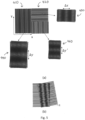
- Fig. 4 illustrates a measurement of a force effect (a force F and a torque M) on the component 100 by determining a relative position change between the first support element 210 and the second support element 230 for an embodiment according to Figure 1 .
- digital image correlation is used as a pixel-based method.
- Part (a) of the figure shows a first image 410 of an optical pattern 222, created in the beam collection element 243 by the first beam 331, and a second image 420 of a second optical pattern 222, here identical to the first, created in the beam collection element 243 by the second beam 332.
- the images 410, 420 are connected by a reflection caused by the mirror 245.
- the points 411, 412, 423 in the first image represent light-transmitting regions or calculation points in the optical pattern 222. They correspond to the calculation points 421, 423, 423 in the second image.
- a pixel-based method comprises measuring positions of the calculation points 411 - 413, 421 - 423 in a state with force and in a state without force and comparing the positions in the state with force with the positions in the state without force.
- a displacement of the positions of the calculation points 411, 412, 413 from the unreflected first beam 331 is shown on the left, as caused by the force.
- a pivot point 430 can be determined, which represents an application position of the torque M
- a magnitude of a horizontal force component of the force F acting on the component 100 can be determined.
- a magnitude of a vertical force component of the force F acting on the component 100 can be determined.
- a magnitude of the torque M also follows from an angle ⁇ .
- a shift of the positions of the calculation points 421, 422, 423 from the mirrored first ray 332 is also shown on the right, which results after deducting a shift of the calculation points 411, 412, 413, which is shown on the left in part (b).
- a value of an axial force component of the force F acting on the component 100 can be determined.
- Fig. 5 illustrates a measurement of a force effect (a force F and a torque M) on the component 100 by determining a relative position change between the first support element 210 and the second support element 230 for an embodiment according to Figure 1 .
- a digital moiré process is used as a pixel-based process.
- Part (a) of the figure shows a first image 410 of an optical pattern 222, created in the beam collection element 243 by the first beam 331, and a second image 420 of a second optical pattern 222, created in the beam collection element 243 by the second beam 332.
- the optical patterns 222 each comprise periodic grating structures in different orientations. By recording the grating structures, their orientation can be compared with and without the application of force. This results in an overlay for the first image 410, which has a moiré pattern 440 with a first period ⁇ y .
- a moiré pattern 450 which has a second period ⁇ x
- a moiré pattern 460 which has a third period ⁇ y' , result accordingly. Force components of the force F in a horizontal, vertical and axial direction can be determined from these periods.
- Part (b) of the figure shows a moiré pattern created by superimposing a lattice structure in a state without force acting on component 100 and a lattice structure in a state with force acting on component 100.
- the lattice structures form an angle ⁇ relative to each other. Based on the angle ⁇ , for example, a magnitude of the torque M can be determined.
- a further step comprises positioning S120 the first support element 210 and the at least one further support element 230 in the initial cavity.
- a further step then comprises forming S130 the initial component in order to form the component and the cavity.
- the forming S130 can in particular comprise cold forming, for example, round pressing for a cylindrical component 100, or cold bulk forming.
- the cavity 110 is also formed by the forming S130 of the structure.
- the forming S130 also effects a plastic joining S140 of the first support element 210 and the second support element 230 in the cavity 110 of the component 100.
- Fig. 7 illustrates further results of embodiments of the method according to Fig. 6 .
- the support elements 210, 230 have a core made of very hard material and an edge region comprising a material that is more easily deformable than the material of the core. The more easily deformable material has been plastically deformed by the forming S130 of the component 100, so that the support elements 210, 230 have been fixed in the resulting cavity 110.
- the support elements 210, 230 comprise a very hard material compared to a material of the component 100, so that during forming S130, the material of the component 100 has been plastically deformed by the hard material of the support elements 210, 230.
- the support elements 210, 230 have thus been fixed in the cavity 110 of the component 100 created by the forming S130.
Landscapes
- Physics & Mathematics (AREA)
- General Physics & Mathematics (AREA)
- Length Measuring Devices By Optical Means (AREA)
- Force Measurement Appropriate To Specific Purposes (AREA)
- Optical Couplings Of Light Guides (AREA)
Claims (8)
- Composant (100) comportant un dispositif formant capteur (200) intégré pour une mesure optique multiaxiale d'une force exercée sur le composant (100), le composant (100) comprenantune cavité (110) ;un premier élément de support (210) comportant un ou plusieurs premiers éléments optiques (220) et un second élément de support (230) comportant un ou plusieurs seconds éléments optiques (240), dans lequel le premier élément de support (210) et le second élément de support (230) sont réalisés dans la cavité (110) et partiellement insérés dans le composant (100) ; etun appareil de transmission (300), lequel est configuré pourêtre connecté à une source d'énergie ettransmettre, lorsqu'il est connecté à la source d'énergie, au moins deux faisceaux (331, 332) dans des directions indépendantes l'une de l'autre, dans lequel les faisceaux (331, 332) s'étendent respectivement entre les premiers éléments optiques (220) et les seconds éléments optiques (240) à travers la cavité (110),dans lequel les premiers éléments optiques (220) et les seconds éléments optiques (240) sont configurés pour générer, sur la base des au moins deux faisceaux (331, 332), des informations concernant un changement de position relative du premier élément de support (210) par rapport au second élément de support (230), et dans lequel l'appareil de transmission (300) est configuré pour fournir les informations pour la mesure de l'action de la force, dans lequel les seconds éléments optiques (240) présentent un miroir (245),caractérisé en ce queles au moins deux faisceaux (331, 332) présentent un faisceau réfléchi (332) et un faisceau non réfléchi (331).
- Composant (100) selon la revendication 1, dans lequel l'appareil de transmission (300) est configuré pour réaliser une ou plusieurs des actions suivantes :connexion à une source lumineuse comme source d'énergie,connexion à une source de courant comme source d'énergie,transmission des informations provenant du composant (100) par une ligne de lumière (320),transmission des informations provenant du composant (100) par une ligne électrique (320).
- Composant (100) selon l'une des revendications précédentes, dans lequel le composant (100) est l'un des composants suivants :un arbre creux,un composant cylindrique creux,un tube,un élément de robot, en particulier un bras de robot,un élément destiné à une construction,un bras de grue,un élément de liaison,une colonne d'une machine-outil,un outil,un porte-outil.
- Composant (100) selon l'une des revendications précédentes, dans lequel les premiers éléments optiques (220) ou les seconds éléments optiques (240) présentent un motif optique (222) et sont configurés pour superposer les au moins deux faisceaux (331, 332) de sorte que les informations comprennent une modification d'une image optique détectée dudit motif.
- Composant (100) selon l'une des revendications 1 à 3, dans lequel les premiers éléments optiques (220) et les seconds éléments optiques (240) forment un interféromètre de Michelson et les informations sont basées sur un motif d'interférence de Michelson.
- Composant (100) selon l'une des revendications 1 à 3, dans lequel au moins l'un des premiers éléments optiques (220) et au moins l'un des seconds éléments optiques (240) présentent respectivement une plaque partiellement réfléchissante (227, 247) et sont configurés pour former un interféromètre de Fabry-Pérot pour au moins l'un des au moins deux faisceaux (331, 332).
- Composant (100) selon l'une des revendications précédentes, dans lequel au moins un autre élément de support comportant un ou plusieurs autres éléments optiques est réalisé dans la cavité (100) et est partiellement inséré dans le composant (100).
- Procédé pour la fabrication d'un composant (100) selon la revendication 1, le procédé comprend les étapes consistant àfournir (S110) un composant de départ comportant une cavité de départ ;positionner (S120) le premier élément de support (210) et l'au moins un autre élément de support (230) dans la cavité de départ ;mouler (S130) le composant de départ afin de réaliser le composant (100) et la cavité (110) ; ainsi queassembler plastiquement (S140) le premier élément de support (210) ainsi que l'au moins un autre élément de support (230) afin de fixer le premier élément de support (210) et l'au moins un autre élément de support (230) dans la cavité (110).
Applications Claiming Priority (2)
| Application Number | Priority Date | Filing Date | Title |
|---|---|---|---|
| DE102020120192.3A DE102020120192A1 (de) | 2020-07-30 | 2020-07-30 | Bauteil mit einer integrierten Sensorvorrichtung für eine optische, mehrachsige Messung einer Krafteinwirkung |
| PCT/EP2021/071303 WO2022023480A1 (fr) | 2020-07-30 | 2021-07-29 | Pièce dotée d'un dispositif de détection intégré pour une mesure optique, sur plusieurs axes, d'une force appliquée |
Publications (2)
| Publication Number | Publication Date |
|---|---|
| EP4189351A1 EP4189351A1 (fr) | 2023-06-07 |
| EP4189351B1 true EP4189351B1 (fr) | 2025-05-21 |
Family
ID=77265085
Family Applications (1)
| Application Number | Title | Priority Date | Filing Date |
|---|---|---|---|
| EP21752045.1A Active EP4189351B1 (fr) | 2020-07-30 | 2021-07-29 | Pièce dotée d'un dispositif de détection intégré pour une mesure optique, sur plusieurs axes, d'une force appliquée |
Country Status (5)
| Country | Link |
|---|---|
| US (1) | US12313485B2 (fr) |
| EP (1) | EP4189351B1 (fr) |
| JP (1) | JP2023545339A (fr) |
| DE (1) | DE102020120192A1 (fr) |
| WO (1) | WO2022023480A1 (fr) |
Families Citing this family (1)
| Publication number | Priority date | Publication date | Assignee | Title |
|---|---|---|---|---|
| WO2022249537A1 (fr) * | 2021-05-24 | 2022-12-01 | ソニーグループ株式会社 | Dispositif capteur |
Family Cites Families (12)
| Publication number | Priority date | Publication date | Assignee | Title |
|---|---|---|---|---|
| DE4132110A1 (de) | 1991-09-26 | 1993-04-01 | Siemens Ag | Kraftsensor |
| CN1692401B (zh) | 2002-04-12 | 2011-11-16 | 雷斯里·R·奥柏梅尔 | 多轴输入转换器装置和摇杆 |
| US20110243730A1 (en) | 2010-12-14 | 2011-10-06 | Eric David Eggleston | Systems and methods for determining deflection of a wind turbine shaft |
| DE102011011392B4 (de) | 2011-02-17 | 2012-10-25 | Ssb Wind Systems Gmbh & Co. Kg | Optische Messeinrichtung für die Verformung eines Rotorblattes einer Windkraftanlage |
| HUP1100633A2 (en) | 2011-11-17 | 2013-06-28 | Pazmany Peter Katolikus Egyetem | Device with optical feedback for measuring force and pressure |
| DE102012005614B4 (de) | 2012-03-22 | 2013-10-17 | Matthias Brenneis | Sensorisches Verbindungselement und Herstellverfahren |
| DE102015106933A1 (de) | 2015-05-04 | 2016-11-10 | Technische Universität Darmstadt | Maschinenelement mit einer Sensoreinrichtung und Verfahren zur Herstellung eines Maschinenelements |
| US10274386B2 (en) * | 2016-06-20 | 2019-04-30 | X Development Llc | Retroreflective multi-axis force torque sensor |
| DE102017101580A1 (de) | 2017-01-26 | 2018-07-26 | Picofine GmbH | Messkopf für ein Laserinterferometer und betreffendes Messverfahren |
| DE102017214352A1 (de) * | 2017-08-17 | 2019-02-21 | Deere & Company | Spektrometrischer Messkopf für forst-, land- und lebensmittelwirtschaftliche Anwendungen |
| US10732061B2 (en) | 2017-09-07 | 2020-08-04 | X Development Llc | Unibody flexure design for displacement-based force/torque sensing |
| DE102018208689A1 (de) | 2018-06-01 | 2019-12-05 | Eolotec Gmbh | Verfahren sowie Vorrichtung zur Ermittlung einer Belastung oder Alterung eines Bauteils |
-
2020
- 2020-07-30 DE DE102020120192.3A patent/DE102020120192A1/de active Pending
-
2021
- 2021-07-29 EP EP21752045.1A patent/EP4189351B1/fr active Active
- 2021-07-29 JP JP2023502737A patent/JP2023545339A/ja active Pending
- 2021-07-29 US US18/015,337 patent/US12313485B2/en active Active
- 2021-07-29 WO PCT/EP2021/071303 patent/WO2022023480A1/fr not_active Ceased
Also Published As
| Publication number | Publication date |
|---|---|
| EP4189351A1 (fr) | 2023-06-07 |
| US12313485B2 (en) | 2025-05-27 |
| DE102020120192A1 (de) | 2022-02-03 |
| JP2023545339A (ja) | 2023-10-30 |
| US20230296460A1 (en) | 2023-09-21 |
| WO2022023480A1 (fr) | 2022-02-03 |
Similar Documents
| Publication | Publication Date | Title |
|---|---|---|
| DE102012111008B4 (de) | Optisches Messverfahren und optische Messvorrichtung zum Erfassen einer Oberflächentopographie | |
| EP1379857B1 (fr) | Ensemble interferometrique permettant de determiner le temps de propagation de la lumiere dans un echantillon | |
| DE102017102343B4 (de) | Sensoranordnung zur Kraft- oder Drehmomentmessung und ein Verfahren zur Herstellung derselben | |
| EP3056934B1 (fr) | Tete de mesure d'un dispositif endoscopique et procede d'inspection et mesure d'un objet | |
| DE102010040143B4 (de) | Lichtwellenleiter-Sensor, Drucksensor, Greiforgan und Sensor-Signalprozessor | |
| DE102008010916A1 (de) | Verfahren und Vorrichtung zur Ermittlung einer Ausrichtung von zwei drehbar gelagerten Maschinenteilen, einer Ausrichtung von zwei hohlzylinderförmigen Maschinenteilen oder zur Prüfung einer Komponente auf Geradheit entlang einer Längsseite | |
| EP2623937B1 (fr) | Dispositif de mesure de position et agencement à plusieurs dispositifs de mesure de position | |
| EP2580563A2 (fr) | Procédé de mesure dynamométrique optique à faibles vibrations, notamment à températures élevées | |
| EP4189351B1 (fr) | Pièce dotée d'un dispositif de détection intégré pour une mesure optique, sur plusieurs axes, d'une force appliquée | |
| DE69428815T2 (de) | Verfahren und System zur Messung dreidimensionaler Verschiebungen | |
| EP0771413B1 (fr) | Methode de mesure de contraintes de torsion et/ou de contraintes axiales sur un arbre rotatif ou sur une piece comparable | |
| EP1849556A1 (fr) | Appareil de serrage avec dispositif de mesure de la distance entre un mandrin et un support de pièce ou d'outil | |
| DE69002702T2 (de) | Verfahren und Gerät, basierend auf faseroptischen Interferometersensoren, zur Analysierung der dynamischen Entstellung einer Struktur oder ihrer Komponenten. | |
| DE10301607B4 (de) | Interferenzmesssonde | |
| WO2008128829A1 (fr) | Procédé et dispositif de mesure de pression | |
| DE102018110381B4 (de) | Vorrichtung zum Aufnehmen von Bildern und Verfahren zur Belastungsanalyse eines Prüfkörpers | |
| DE19905687A1 (de) | Vorrichtung zur Bestimmung der Biegebeanspruchung von Bauteilen | |
| DE102006007406B3 (de) | Schubmessbrücke und Verfahren zur messtechnischen Erfassung des Schubes von Triebwerken | |
| DE102005025414B4 (de) | Verfahren und Vorrichtung zum Prüfen einer axialen Position eines Piezoaktors in einem Gehäuse während eines Betriebs des Piezoaktors | |
| EP1012534B1 (fr) | Procede et dispositif pour la determination de deformations et d'allongements sur des corps curvilignes | |
| DE29808683U1 (de) | Anordnung zur Sensierung der dritten Raumrichtung bei einem mikromechanischen Tastsystem | |
| DE102006060584B4 (de) | Verfahren und Vorrichtung zur Messung von Verschiebungen und/oder einer Geometrie von Mikrostrukturen | |
| DE102004045802B4 (de) | Interferometrisches System mit Referenzfläche mit einer verspiegelten Zone | |
| DE102012104884A1 (de) | Faseroptischer Kraftaufnehmer und optisches Messverfahren | |
| DE102024134337B3 (de) | Verfahren und System zum quantitativen Erkennen von Verformungen und/oder Bewegungen eines Objekts |
Legal Events
| Date | Code | Title | Description |
|---|---|---|---|
| STAA | Information on the status of an ep patent application or granted ep patent |
Free format text: STATUS: UNKNOWN |
|
| STAA | Information on the status of an ep patent application or granted ep patent |
Free format text: STATUS: THE INTERNATIONAL PUBLICATION HAS BEEN MADE |
|
| PUAI | Public reference made under article 153(3) epc to a published international application that has entered the european phase |
Free format text: ORIGINAL CODE: 0009012 |
|
| STAA | Information on the status of an ep patent application or granted ep patent |
Free format text: STATUS: REQUEST FOR EXAMINATION WAS MADE |
|
| 17P | Request for examination filed |
Effective date: 20221222 |
|
| AK | Designated contracting states |
Kind code of ref document: A1 Designated state(s): AL AT BE BG CH CY CZ DE DK EE ES FI FR GB GR HR HU IE IS IT LI LT LU LV MC MK MT NL NO PL PT RO RS SE SI SK SM TR |
|
| DAV | Request for validation of the european patent (deleted) | ||
| DAX | Request for extension of the european patent (deleted) | ||
| GRAP | Despatch of communication of intention to grant a patent |
Free format text: ORIGINAL CODE: EPIDOSNIGR1 |
|
| STAA | Information on the status of an ep patent application or granted ep patent |
Free format text: STATUS: GRANT OF PATENT IS INTENDED |
|
| INTG | Intention to grant announced |
Effective date: 20250314 |
|
| GRAS | Grant fee paid |
Free format text: ORIGINAL CODE: EPIDOSNIGR3 |
|
| GRAA | (expected) grant |
Free format text: ORIGINAL CODE: 0009210 |
|
| STAA | Information on the status of an ep patent application or granted ep patent |
Free format text: STATUS: THE PATENT HAS BEEN GRANTED |
|
| AK | Designated contracting states |
Kind code of ref document: B1 Designated state(s): AL AT BE BG CH CY CZ DE DK EE ES FI FR GB GR HR HU IE IS IT LI LT LU LV MC MK MT NL NO PL PT RO RS SE SI SK SM TR |
|
| REG | Reference to a national code |
Ref country code: GB Ref legal event code: FG4D Free format text: NOT ENGLISH |
|
| REG | Reference to a national code |
Ref country code: DE Ref legal event code: R081 Ref document number: 502021007549 Country of ref document: DE Owner name: TECHNISCHE UNIVERSITAET DARMSTADT, KOERPERSCHA, DE Free format text: FORMER OWNER: ANMELDERANGABEN UNKLAR / UNVOLLSTAENDIG, 80297 MUENCHEN, DE |
|
| REG | Reference to a national code |
Ref country code: CH Ref legal event code: EP |
|
| REG | Reference to a national code |
Ref country code: IE Ref legal event code: FG4D Free format text: LANGUAGE OF EP DOCUMENT: GERMAN Ref country code: DE Ref legal event code: R096 Ref document number: 502021007549 Country of ref document: DE |
|
| REG | Reference to a national code |
Ref country code: NL Ref legal event code: MP Effective date: 20250521 |
|
| PG25 | Lapsed in a contracting state [announced via postgrant information from national office to epo] |
Ref country code: PT Free format text: LAPSE BECAUSE OF FAILURE TO SUBMIT A TRANSLATION OF THE DESCRIPTION OR TO PAY THE FEE WITHIN THE PRESCRIBED TIME-LIMIT Effective date: 20250922 Ref country code: FI Free format text: LAPSE BECAUSE OF FAILURE TO SUBMIT A TRANSLATION OF THE DESCRIPTION OR TO PAY THE FEE WITHIN THE PRESCRIBED TIME-LIMIT Effective date: 20250521 Ref country code: ES Free format text: LAPSE BECAUSE OF FAILURE TO SUBMIT A TRANSLATION OF THE DESCRIPTION OR TO PAY THE FEE WITHIN THE PRESCRIBED TIME-LIMIT Effective date: 20250521 |
|
| PGFP | Annual fee paid to national office [announced via postgrant information from national office to epo] |
Ref country code: DE Payment date: 20250722 Year of fee payment: 5 |
|
| REG | Reference to a national code |
Ref country code: LT Ref legal event code: MG9D |
|
| PG25 | Lapsed in a contracting state [announced via postgrant information from national office to epo] |
Ref country code: NO Free format text: LAPSE BECAUSE OF FAILURE TO SUBMIT A TRANSLATION OF THE DESCRIPTION OR TO PAY THE FEE WITHIN THE PRESCRIBED TIME-LIMIT Effective date: 20250821 Ref country code: GR Free format text: LAPSE BECAUSE OF FAILURE TO SUBMIT A TRANSLATION OF THE DESCRIPTION OR TO PAY THE FEE WITHIN THE PRESCRIBED TIME-LIMIT Effective date: 20250822 |
|
| PG25 | Lapsed in a contracting state [announced via postgrant information from national office to epo] |
Ref country code: NL Free format text: LAPSE BECAUSE OF FAILURE TO SUBMIT A TRANSLATION OF THE DESCRIPTION OR TO PAY THE FEE WITHIN THE PRESCRIBED TIME-LIMIT Effective date: 20250521 Ref country code: PL Free format text: LAPSE BECAUSE OF FAILURE TO SUBMIT A TRANSLATION OF THE DESCRIPTION OR TO PAY THE FEE WITHIN THE PRESCRIBED TIME-LIMIT Effective date: 20250521 |
|
| PG25 | Lapsed in a contracting state [announced via postgrant information from national office to epo] |
Ref country code: BG Free format text: LAPSE BECAUSE OF FAILURE TO SUBMIT A TRANSLATION OF THE DESCRIPTION OR TO PAY THE FEE WITHIN THE PRESCRIBED TIME-LIMIT Effective date: 20250521 |
|
| PGFP | Annual fee paid to national office [announced via postgrant information from national office to epo] |
Ref country code: GB Payment date: 20250724 Year of fee payment: 5 |
|
| PG25 | Lapsed in a contracting state [announced via postgrant information from national office to epo] |
Ref country code: HR Free format text: LAPSE BECAUSE OF FAILURE TO SUBMIT A TRANSLATION OF THE DESCRIPTION OR TO PAY THE FEE WITHIN THE PRESCRIBED TIME-LIMIT Effective date: 20250521 |
|
| PGFP | Annual fee paid to national office [announced via postgrant information from national office to epo] |
Ref country code: AT Payment date: 20251020 Year of fee payment: 5 |
|
| PG25 | Lapsed in a contracting state [announced via postgrant information from national office to epo] |
Ref country code: RS Free format text: LAPSE BECAUSE OF FAILURE TO SUBMIT A TRANSLATION OF THE DESCRIPTION OR TO PAY THE FEE WITHIN THE PRESCRIBED TIME-LIMIT Effective date: 20250821 |
|
| PG25 | Lapsed in a contracting state [announced via postgrant information from national office to epo] |
Ref country code: IS Free format text: LAPSE BECAUSE OF FAILURE TO SUBMIT A TRANSLATION OF THE DESCRIPTION OR TO PAY THE FEE WITHIN THE PRESCRIBED TIME-LIMIT Effective date: 20250921 |
|
| PG25 | Lapsed in a contracting state [announced via postgrant information from national office to epo] |
Ref country code: LV Free format text: LAPSE BECAUSE OF FAILURE TO SUBMIT A TRANSLATION OF THE DESCRIPTION OR TO PAY THE FEE WITHIN THE PRESCRIBED TIME-LIMIT Effective date: 20250521 |
|
| PG25 | Lapsed in a contracting state [announced via postgrant information from national office to epo] |
Ref country code: SM Free format text: LAPSE BECAUSE OF FAILURE TO SUBMIT A TRANSLATION OF THE DESCRIPTION OR TO PAY THE FEE WITHIN THE PRESCRIBED TIME-LIMIT Effective date: 20250521 Ref country code: DK Free format text: LAPSE BECAUSE OF FAILURE TO SUBMIT A TRANSLATION OF THE DESCRIPTION OR TO PAY THE FEE WITHIN THE PRESCRIBED TIME-LIMIT Effective date: 20250521 |
|
| PG25 | Lapsed in a contracting state [announced via postgrant information from national office to epo] |
Ref country code: CZ Free format text: LAPSE BECAUSE OF FAILURE TO SUBMIT A TRANSLATION OF THE DESCRIPTION OR TO PAY THE FEE WITHIN THE PRESCRIBED TIME-LIMIT Effective date: 20250521 |
|
| PG25 | Lapsed in a contracting state [announced via postgrant information from national office to epo] |
Ref country code: EE Free format text: LAPSE BECAUSE OF FAILURE TO SUBMIT A TRANSLATION OF THE DESCRIPTION OR TO PAY THE FEE WITHIN THE PRESCRIBED TIME-LIMIT Effective date: 20250521 |
|
| PG25 | Lapsed in a contracting state [announced via postgrant information from national office to epo] |
Ref country code: SK Free format text: LAPSE BECAUSE OF FAILURE TO SUBMIT A TRANSLATION OF THE DESCRIPTION OR TO PAY THE FEE WITHIN THE PRESCRIBED TIME-LIMIT Effective date: 20250521 |
|
| PG25 | Lapsed in a contracting state [announced via postgrant information from national office to epo] |
Ref country code: IT Free format text: LAPSE BECAUSE OF FAILURE TO SUBMIT A TRANSLATION OF THE DESCRIPTION OR TO PAY THE FEE WITHIN THE PRESCRIBED TIME-LIMIT Effective date: 20250521 |
|
| REG | Reference to a national code |
Ref country code: CH Ref legal event code: H13 Free format text: ST27 STATUS EVENT CODE: U-0-0-H10-H13 (AS PROVIDED BY THE NATIONAL OFFICE) Effective date: 20260224 Ref country code: DE Ref legal event code: R097 Ref document number: 502021007549 Country of ref document: DE |
|
| PG25 | Lapsed in a contracting state [announced via postgrant information from national office to epo] |
Ref country code: RO Free format text: LAPSE BECAUSE OF FAILURE TO SUBMIT A TRANSLATION OF THE DESCRIPTION OR TO PAY THE FEE WITHIN THE PRESCRIBED TIME-LIMIT Effective date: 20250521 |
|
| PG25 | Lapsed in a contracting state [announced via postgrant information from national office to epo] |
Ref country code: LU Free format text: LAPSE BECAUSE OF NON-PAYMENT OF DUE FEES Effective date: 20250729 |
|
| REG | Reference to a national code |
Ref country code: BE Ref legal event code: MM Effective date: 20250731 |
|
| PLBE | No opposition filed within time limit |
Free format text: ORIGINAL CODE: 0009261 |
|
| STAA | Information on the status of an ep patent application or granted ep patent |
Free format text: STATUS: NO OPPOSITION FILED WITHIN TIME LIMIT |
|
| REG | Reference to a national code |
Ref country code: CH Ref legal event code: L10 Free format text: ST27 STATUS EVENT CODE: U-0-0-L10-L00 (AS PROVIDED BY THE NATIONAL OFFICE) Effective date: 20260402 |
|
| PG25 | Lapsed in a contracting state [announced via postgrant information from national office to epo] |
Ref country code: BE Free format text: LAPSE BECAUSE OF NON-PAYMENT OF DUE FEES Effective date: 20250731 |
|
| PG25 | Lapsed in a contracting state [announced via postgrant information from national office to epo] |
Ref country code: FR Free format text: LAPSE BECAUSE OF NON-PAYMENT OF DUE FEES Effective date: 20250731 |
|
| PG25 | Lapsed in a contracting state [announced via postgrant information from national office to epo] |
Ref country code: CH Free format text: LAPSE BECAUSE OF NON-PAYMENT OF DUE FEES Effective date: 20250731 |
|
| 26N | No opposition filed |
Effective date: 20260224 |