EP4189708B1 - Rheostat - Google Patents
Rheostat Download PDFInfo
- Publication number
- EP4189708B1 EP4189708B1 EP21752083.2A EP21752083A EP4189708B1 EP 4189708 B1 EP4189708 B1 EP 4189708B1 EP 21752083 A EP21752083 A EP 21752083A EP 4189708 B1 EP4189708 B1 EP 4189708B1
- Authority
- EP
- European Patent Office
- Prior art keywords
- tube
- rheostat
- resistive
- resistance
- cursors
- Prior art date
- Legal status (The legal status is an assumption and is not a legal conclusion. Google has not performed a legal analysis and makes no representation as to the accuracy of the status listed.)
- Active
Links
Images



Classifications
-
- H—ELECTRICITY
- H01—ELECTRIC ELEMENTS
- H01C—RESISTORS
- H01C10/00—Adjustable resistors
- H01C10/30—Adjustable resistors the contact sliding along resistive element
- H01C10/301—Adjustable resistors the contact sliding along resistive element consisting of a wire wound resistor
-
- H—ELECTRICITY
- H01—ELECTRIC ELEMENTS
- H01C—RESISTORS
- H01C10/00—Adjustable resistors
- H01C10/16—Adjustable resistors including plural resistive elements
- H01C10/20—Contact structure or movable resistive elements being ganged
-
- H—ELECTRICITY
- H01—ELECTRIC ELEMENTS
- H01C—RESISTORS
- H01C10/00—Adjustable resistors
- H01C10/30—Adjustable resistors the contact sliding along resistive element
- H01C10/38—Adjustable resistors the contact sliding along resistive element the contact moving along a straight path
-
- H—ELECTRICITY
- H01—ELECTRIC ELEMENTS
- H01C—RESISTORS
- H01C10/00—Adjustable resistors
- H01C10/50—Adjustable resistors structurally combined with switching arrangements
Definitions
- the present invention relates to an ohmic conductor whose resistance can be varied, otherwise called a rheostat.
- Rheostats are used to vary the ohmic value of a resistive element, particularly in the case of loads used for testing electrical sources.
- the rheostats are often replaced by electronic loads which are electronic circuits which adjust the intensity which they absorb to the voltage value which is put at their terminals to appear as resistive dipoles of an ohmic value which can be easily ordered.
- These electronic loads have advantages in terms of precision, ease of adjustment, control by communication in digital form with external controllers.
- Rheostats however, have advantages which lead them to still be used to this day, in particular the fact that their resistive circuit is made with passive resistive conductors and therefore do not present the characteristics of distortion and sensitivity to electromagnetic disturbances of electronic circuits. .
- the rheostat therefore has greater reliability and ohmic value precision than the electronic loads mentioned above.
- rheostat comprising several resistive windings
- the latter can be arranged in parallel.
- the resistive windings are electrically connected in parallel
- one of the disadvantages lies in particular in that they present limited adjustment dynamics linked to the movement of a cursor along the resistive windings.
- such mounting of the resistive windings in parallel turns out to be complex and expensive to carry out.
- the document CN 111403136 A discloses a rheostat for battery testing equipment, comprising resistive tubes and a slider circulating on each of the tubes.
- the aim of the present invention is therefore to improve the structure and operation of a rheostat and in particular to increase its ohmic value while simplifying its design.
- the invention also makes it possible to reduce the production cost of the rheostat while allowing its operation in direct or alternating current, for the same rheostat.
- the invention also has the advantage of optimizing the process making it possible to vary the ohmic resistance of the rheostat while increasing the lifespan of the latter.
- the invention relates to a rheostat comprising at least one electrical input and one electrical output, the rheostat comprising at least a first resistive tube and a second resistive tube electrically arranged in series with respect to each other and on each of which a cursor circulates, the electrical input being connected to the first resistive tube and the electrical output being connected to at least one of the cursors, a first switch and a second switch being arranged between each of the cursors, respectively of the first resistive tube and of the second resistive tube and the electrical output, characterized in that the rheostat comprises an inter-tube connection point arranged between a start of the second resistive tube and an end of the first resistive tube, the rheostat being configured to authorize contact of the cursors at the level of the inter-tube connection point as well as a change of state of the first switch and the second switch when the cursors are arranged at the level of the inter-tube connection point.
- the resistive tubes are composed of at least one ceramic tube and an electrical winding on which the cursor circulates. The circulation of the cursor along the electrical winding of the resistive tube then makes it possible to vary the ohmic value of the rheostat.
- the inter-tube connection point we understand from the arrangement of the inter-tube connection point that the resistive tubes of the rheostat are arranged head to tail from each other, thus making it possible to electrically connect the end of the first resistive tube with the start of the second resistive tube.
- the inter-tube connection point then corresponds to a point between the resistive tubes with zero potential difference, the contact of the cursor to said inter-tube connection point therefore having the advantage of limiting the generation of electric arcs which may ultimately decrease the lifespan of said switch.
- Advantage is taken of such a configuration of the rheostat in that it allows the use of lower cost switches, while operating the rheostat in direct or alternating current, without modifications to the switches.
- each of the first resistive tube and the second resistive tube can be replaced by a group of several resistive tubes whose electrical windings are connected in parallel.
- all of the resistive tubes of a group of tubes is traversed by a plurality of cursors connected to the same electrical potential.
- each of the groups of tubes that the rheostat includes can include a number of tubes different from each other, within the same rheostat.
- the rheostat comprises at least one box in which at least the first resistive tube, the second resistive tube and a third resistive tube are arranged, each of the resistive tubes being arranged head to tail relative to an adjacent resistive tube of such that at least one start of one of said resistive tubes faces an end of another resistive tube, the first resistive tube, the second resistive tube and the third resistive tube being electrically arranged in series with each other relation to others.
- first inter-tube connection point at a first end of the second resistive tube and a second inter-tube connection point at a second end of the second resistive tube, the first inter-tube connection point being connected to one end of the first resistive tube while the second inter-tube connection point is connected to a start of the third resistive tube.
- the rheostat comprises at least one switch control unit and at least two sensors capable of determining the position of the cursor on its resistive tube, the two sensors being able to transmit the position of the cursor to the control unit switches.
- a first sensor is then positioned in the rheostat such that it is facing the start of at least one of the resistive tubes of the rheostat while a second sensor is positioned facing the end of said resistive tube, in the direction movement of the cursor assigned to the tube.
- at least one of the first sensor or the second sensor is able to detect the position of the cursor at at least one of the inter-tube connection points of the rheostat and thus transmit this position to the control unit of the switches, so as to authorize switching of the switch(es), if applicable.
- the sliders of each of the resistive tubes are mechanically linked to each other such that they move simultaneously along their respective resistive tube.
- the set of cursors associated with each of the resistive tubes then forms a group of movable cursors of the rheostat, moving in an identical manner along their respective resistive tube.
- the switch is an electromechanical relay or an electronic switch, that is to say for example one or more transistors.
- the switch can then be a position memory relay with at least two coils, or in other words a latching or bistable relay, that is to say a relay which retains its open or closed position when it is off.
- a last resistive tube of the series of resistive tubes is electrically connected to the electrical output by means of a switch.
- the switch makes it possible in particular to connect the end of the last resistive tube of the series of resistive tubes directly to the electrical output of the rheostat.
- the switch allows on the one hand an exit of the electric current from the rheostat according to a maximum resistance of the latter and on the other hand allows the circulation of electric current to be interrupted in the resistive tubes when the cursors are arranged on an inter-tube connection point.
- the rheostat may comprise at least one safety relay positioned between the electrical input and the electrical output, the safety relay being able to interrupt or authorize a flow of current through the series of resistive tubes.
- the safety relay is positioned between the input of the rheostat and the first resistive tube of said rheostat and makes it possible at least to cut off an electrical supply to the resistive tubes during a malfunction of the rheostat. More precisely, when detecting a malfunction of the rheostat, the control unit cuts off the electrical supply to the resistive tubes by means of the safety relay.
- the switch can then be a position memory relay with two coils, or in other words a latching or bistable relay.
- the switch can bring the cursor to the level of the inter-tube connection point before switching the switch, in order to limit damage to said switch. In this last configuration, the switch corresponds to a relay without latching.
- the rheostat comprises at least one motorized movement member for the cursors.
- the motorized movement member therefore makes it possible to move the group of movable cursors along the resistive tubes in order to vary the resistance of the rheostat.
- the member for simultaneously moving the cursors can be manually controlled.
- the invention also relates to a method of controlling a rheostat according to the preceding characteristics, during which the switch is switched when at least one of the cursors is positioned at the inter-tube connection point.
- a low potential difference can in particular be obtained by sizing the switches and means a value between 0 and 20 V.
- the first switch and the second switch are both switched when the cursors associated with them are positioned at the inter-tube connection point.
- switching of the switch is prevented when at least one of the cursors is positioned outside the inter-tube connection point(s).
- the first sensor or the second sensor is able to determine whether the cursor is arranged at the inter-tube connection point, said sensors thus transmitting the position of said cursor to the switch control unit which manages the switching of the switch .
- the control unit blocks the switching of the switch, thus preventing its interrupting operation or authorization of the switch. passage of electric current through the slider associated with the switch.
- the electric current flows at least partly through the first resistive tube when the first switch is closed.
- the first switch is conducting.
- the first switch is associated with the cursor of the first resistive tube and that when the latter is closed, the other switches of the rheostat are open.
- the current passes both in part through the first resistive tube and its associated slider to the electrical output of the rheostat, the other open switches preventing electrical circulation in the sliders with which they are associated.
- the electric current flows through the first resistive tube and at least part of the second resistive tube when the first switch is open and the second switch is closed.
- the second switch is electrically connected to the slider of the second resistive tube.
- the current flows in the first resistive tube without crossing the cursor of said first resistive tube and then travels at least in part through the second resistive tube passing through the inter-tube connection point, then passes through the cursor of said second resistive tube to be brought to the electrical output of the rheostat.
- FIG. 1 illustrates a rheostat 1 according to the invention comprising at least one box 2 in which a plurality of resistive tubes 4 are housed.
- the rheostat 1 according to the invention is a rheostat 1 of the rectilinear type which can be used as a variable load to carry out tests device or scheduled battery discharges, for their maintenance.
- the plurality of resistive tubes 4 of the rheostat 1 then constitutes the linear resistance of the rheostat 1 and each of the resistive tubes 4 comprises at least one ceramic tube surrounded by an electrical winding intended to be passed through by the electric current and used to vary the resistance of rheostat 1.
- each of the resistive tubes 4 comprises an associated maximum resistance, the total resistance of the rheostat 1 being the sum of the resistances of each of the resistive tubes 4.
- the rheostat 1 makes it possible to vary the intensity of the electric current which comes out of it. More precisely, the intensity of the electric current varies as it passes from one resistive tube 4 to the other, that is to say when the ohmic value of rheostat 1 varies.
- an electrical input 8 of the rheostat and an electrical output 10 of said rheostat.
- the electrical input 8 of the rheostat 1 ensures the entry of electric current into the rheostat 1 so that the latter passes through at least part of the plurality of resistive tubes 4 of the rheostat 1, then leaves the latter via its output electrical 10.
- the resistive tubes 4 of the plurality of resistive tubes 4 are then arranged in series with each other, such that an end 12 of a resistive tube 4 is electrically connected to the start 14 of another tube resistive 4.
- the resistive tubes 4 are arranged superimposed on each other in the rheostat box and in such a way that the adjacent resistive tubes are arranged head to tail in relation to each other, the resistive tubes 4 nevertheless being electrically connected in series with each other.
- each of the groups of resistive tubes can include a number of resistive tubes different from each other, within the same rheostat.
- first resistive tube 4a and a second resistive tube 4b of the rheostat 1 each comprising a start 14 of tube and an end 12 of tube, electrically connected by an inter-tube connection point 16.
- the start 14a of the first resistive tube 4a is then electrically connected to the electrical input 8 of the rheostat 1, while the end 12a of the first resistive tube 4a is electrically connected to the start 14b of the second resistive tube 4b.
- the electrical connection made between the first resistive tube 4a and the second resistive tube 4b then constitutes a first inter-tube connection point 16a.
- a second inter-tube connection point 16b located between an end 12b of the second resistive tube 4b and a start 14c of a third resistive tube 4c.
- a third inter-tube connection point 16c is also arranged between an end 12c of the third resistive tube 4c and a start 14d of a fourth resistive tube 4d.
- a fourth inter-tube connection point 16d is arranged between an end 12d of the fourth resistive tube 4d and a start 14e of a fifth resistive tube 4e.
- inter-tube connection points 16 make it possible to constitute switching points with low or zero potential difference and also allow the use of lower cost switches while operating the direct current rheostat or alternative.
- the use of inter-tube connection points will be explained later in the detailed description.
- a first cursor 6a and a second cursor 6b circulate respectively against the first resistive tube 4a and against the second resistive tube 4b.
- the first cursor 6a is then able to move along the first resistive tube 4a between its start 14a and its end 12a.
- the second cursor 6a is able to move on the second resistive tube 4b between its start 14b and its end 12b.
- Rheostat 1 includes as many cursors 6 as it has resistive tubes and according to the example described here, rheostat 1 includes five resistive tubes 4 and five cursors 6.
- the first cursor 6a and the second cursor 6b, and any other cursors are mechanically connected together, such that they move simultaneously along the first resistive tube 4a and the second resistive tube 4b respectively.
- the mechanical connection between the first cursor 6a and the second cursor 6b that these move in an identical manner along their respective resistive tube 4a, 4b, so that all of the cursors 6 of the rheostat 1 forms a group of movable cursors 60.
- the rheostat 1 then also comprises at least one motorized movement member 18 of the group of movable cursors 60 capable of allowing the movement of the latter along the resistive tubes 4.
- the slider 6 is a wiper which ensures electrical contact on the winding of the resistive tube, and through which the electric current passes to bypass part of this winding.
- the rheostat 1 comprises at least one switch 20 arranged between at least one of the cursors 6 and the electrical output 10 of the rheostat.
- the switch 20 has for function of connecting or disconnecting the cursor 6 from the resistive tube 4 with which it is associated with the electrical output 10 of the rheostat, depending on whether said switch 20 is closed or open.
- the switch 20 can take the form of an electromechanical relay, in particular with two coils and corresponds to a latching or bistable relay.
- the switch 20 can also take the form of an electronic relay, that is to say using one or more transistors.
- Each of the switches can take the form of a position memory relay equipped with two coils making it possible to guarantee the maintenance of an electrical contact at the level of the switch and thus avoid the formation of an electric arc when the power is turned back on.
- a first switch 20a is placed between the first cursor 6a and the electrical output 10 of the rheostat 1 and a second switch 20b is placed between the second cursor 6b and the electrical output 10 of the rheostat 1
- the first switch 20a is able to allow the circulation of electric current through the first cursor 6a
- the second switch 20b is able to authorize the circulation of electric current through the second cursor 6b.
- the rheostat 1 comprises at least one control unit 22 of said switches 20.
- At least two sensors 24 are integral with the box 2 of the rheostat, such that they are facing the start 14 and the end 12 of the resistive tubes 4. More precisely, a first sensor 24a is positioned facing the start 14a of the first resistive tube 4a and a second sensor 24b is positioned opposite the end 12a of said first resistive tube 4a, each of the first sensor 24a and the second sensor 24b being able to determine the position of the cursors 6 of the group of movable cursors 60.
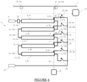
- At least one contact member 25 is positioned at one end of the group of movable cursors 60 such that said contact member 25 is able to cooperate by contact or magnetically with the sensors 24 previously mentioned and such that this is particularly visible to figures 3 And 4 .
- the contact member 25 cooperates with the first sensor 24a in order to indicate to the control unit 22 the position of the group of movable cursors 60 relative to the resistive tubes 6. This position corresponds here to the start 12a of the first resistive tube 6a, at the second inter-tube connection point 16b and at the fourth inter-tube connection point 16d.
- the group of movable cursors 60 is able to move in the direction of the end 12a of the first resistive tube 6a such that the contact member 25 cooperates with the second sensor 24b, this cooperation indicating to the control unit 22 the position of the group of movable cursors 60 at the end 12a of the first resistive tube 6a, the first inter-tube connection point 16a and the third inter-tube connection point 16c.
- Each of the first sensor 24a and the second sensor 24b is then capable of transmitting the position of the first cursor 6a, and of the other cursors 6 included in the group of movable cursors 60, through contact with the contact member 25, to the the control unit 22 of the switches 20.
- the control unit 22 orders the opening or closing of one of the switches 20 depending on the position of the cursor 6 received by the sensors 24.
- the second sensor 24b is able to detect the position of the first cursor 6a at the first inter-tube connection point 16a as previously mentioned.
- the rheostat can comprise a plurality of sensors arranged on the plurality of resistive tubes, at each of their beginnings and ends. We then understand that in such a configuration, the contact of each of the cursors against one of the sensors positioned on one of the resistive tubes of the rheostat indicates the position of said cursor to the control unit.
- the rheostat 1 is configured to authorize contact of the cursor 6 of one of the resistive tubes 4 at one of the inter-tube connection points 16.
- the switching of the switch 20 from one position closed to an open position, and vice versa is carried out only at the inter-tube connection point 16 corresponding to a point of low or zero potential difference.
- the formation of electric arcs at the level of the switch 20 due to the inappropriate position of the cursor 6 on the resistive tube 4 when switching the switch 20 the formation of electric arcs potentially causing premature damage to the latter.
- At least one safety relay 26 is positioned between the electrical input 8 and the electrical output 10 of the rheostat 1, the safety relay 26 being capable of interrupting the circulation of electric current in the resistive tubes 4 of the rheostat 1 More precisely, the safety relay 26 is positioned between the electrical input 8 of the rheostat 1 and the first resistive tube 4a and has the function of preventing the passage of electric current in the resistive tubes 4 of the rheostat 1 in the event. malfunction of the rheostat 1 or during an involuntary interruption of the operation of the rheostat 1. In these cases, the control unit 22 interrupts the electrical supply to the resistive tubes 4 by means of the safety relay 26 while holding the switches in their position.
- the last resistive tube 4 of the series of resistive tubes 4 of the rheostat is electrically connected to the electrical output 10 by means of a switch 28. More precisely, the switch 28 electrically connects an end 12th of the fifth resistive tube 4th at the electrical output 10.
- the switch 28 allows on the one hand, when it is in a closed position, to use the rheostat in its maximum resistance since all the resistive tubes of the series of resistive tubes are traversed by the electric current, and also allows, when it is open, to prohibit this circulation, in particular when the cursors 6 are arranged on one of the points of inter-tube connection 16a, 16b.
- a collar 30 can be positioned at the end 12th of the fifth resistive tube 4e.
- the function of the collar 30 is to allow the circuit of the rheostat 1 to be interrupted when a fifth cursor 6e of the fifth resistive tube 4e is brought into contact with said collar 30 by the control unit 22.
- the collar 30 is an electrically insulator mounted at the end of the last resistive tube and on which the cursor 6e can rub, thus interrupting the circulation of current in the series of resistive tubes 4. Such an interruption occurs when the cursors 6 are placed on the first and third point of inter-tube connection 16a, 16c, the circulation of current in the last slider then being prevented by the collar 30.
- bistable switches thus making it possible to do without the safety relay mentioned above.
- a first step of the method consists of moving one of the cursors 6 of one of the resistive tubes 4 as a function of the desired resistance of the rheostat 1, that is to say as a function of the intensity of the electric current desired at the output electrical 10 of the rheostat 1.
- the control unit 22 of the switches 20 then has the function of on the one hand determining which cursor 6 associated with one of the resistive tubes 4 is to be moved and its position on the resistive tube 4 to obtain the resistance requested. Once this determination has been made, the control unit 22 generates a control instruction to the motorized movement member 18 of the cursors 6 so that the latter brings the cursor 6 previously identified to one of the inter-tube connection points 16 of the resistive tube 4 associated with said cursor 6.
- one of the sensors 24 of the rheostat 1 determines that said cursor 6 is in position at the inter-tube connection point 16 by means of cooperation with the contact member 25 carried by the group of moving cursors 60 and transmits this information to the control unit 22 of the switches 20.
- the control unit 22 of the switches 20 switches the switch 20 associated with the cursor 6 previously identified to position it in a closed state so that the electric current passes through at least one of the resistive tubes 4 arranged between the electrical input 8 and said cursor 6, then joins the electrical output 10 of the rheostat 1.
- Such switching to an open state or a closed state is illustrated by the reference 29 on the figures 3 And 4 .
- the control unit 22 generates a control instruction to the motorized movement member 18 so that the latter brings the cursor 6 identified to a point on the resistive tube 4 corresponding to the desired resistance. In this way, the desired resistance is obtained at the electrical output 10 of the rheostat 1 without the switching of the switch 20 forming an electric arc which could ultimately damage it.
- control unit 22 determines if a new cursor must be used, what must be the new cursor 6 used as well as its position on its associated resistive tube 4 to obtain the new desired resistance.
- the control unit 22 generates a control instruction to the motorized movement member 18 of the cursors 6 in order to bring the cursor 6 previously used during the first step at the inter-tube connection point 16 of the resistive tube 4 identified previously.
- the control unit 22 switches the switch 20 associated with the cursor 6 of the first step, here in an open position, in order to prevent the passage of electric current through said cursor 6 with which he is associated.
- control unit 22 switches the switch 20 associated with said new cursor 6 in a closed position in order to authorize the passage of electric current in the resistive tubes 4 between the electrical input 8 and said new cursor 6.
- Confirmation of the position of this new cursor 6 on an inter-tube connection point can be obtained by detection carried out by one of the position sensors 24 following contact with the contact member 25 carried by the group of mobile cursors 60 , as mentioned previously.
- control unit 22 generates a control instruction to the motorized movement member 18 so that the latter brings the new cursor 6 identified during the fourth step to the point on its resistive tube 4 making it possible to obtain the new desired resistance.
- each of the resistive tubes of the rheostat has a resistance of fifty ohms, this value being given by way of example and can be different and distinct for each of the resistive tubes of the rheostat.
- the control unit 22 of the switches 20 determines during the first step, what pair of resistive tube 4 and slider 6 must be used to obtain this resistance of twenty-five ohms.
- the control unit 22 determines that the first cursor 6a of the first resistive tube 4a must be positioned substantially equidistant from the start 14a and the end 12a of the first resistive tube 4a.
- control unit 22 generates a control instruction to the motorized movement member 18 so that the latter brings the first cursor 6a to the first inter-tube connection point 16a positioned at the end 12a of the first resistive tube 4a .
- the control unit 22 switches (arrow 29) the first switch 20a to a closed position. In this way, the electric current passes through the first resistive tube 4a until its end 12a, then the first cursor 6a to arrive at the electrical output 10 of the rheostat 1.
- control unit 22 generates a control instruction to the motorized movement member 18 so that the latter brings the first cursor 6a to the middle of the first tube 4a.
- a rheostat 1 having a resistance of twenty-five ohms without having produced electric arcs during the switching of the switch 20.
- the control unit 22 In the case where it is desired to modify the resistance of the rheostat 1 previously established at twenty-five ohms, for a resistance of two hundred and twenty-five ohms, the control unit 22 generates a control instruction to the displacement member motorized 18 so that it brings the first cursor 6a to the first inter-tube connection point 16a of the first resistive tube 4a. Once the first inter-tube connection point 16a reached by the first cursor 6a, the second sensor 24b transmits the information to the control unit 22 of the switches 20 so that it switches the first switch 20a to an open position.
- control unit 22 determines the new resistive tube 4 - cursor 6 pair to be used, as well as the position of said cursor 6 on its associated resistive tube 4, in order to obtain the resistance of two hundred and twenty-five ohms generated by the rheostat 1. In the present case and for resistive tubes each of fifty ohms, it is the fifth cursor 6th and the fifth resistive tube 4e.
- the control unit 22 then generates a control instruction to the movement member motorized 18 so that it brings the fifth cursor 6th to the fourth inter-tube connection point 16d of the fifth resistive tube 4e, here located at the start 14th of the latter.
- the first sensor 24a then confirms the position of the fifth cursor 6e at the fourth inter-tube connection point 16d of said fifth resistive tube 4e and transmits this information to the control unit 22.
- the control unit 22 can switch the fifth switch 20e of the fifth resistive tube 4e in a closed position so that the electric current passes through all of the resistive tubes 4 positioned between the electrical input 8 and the fifth cursor 6e.
- control unit 22 generates a new control instruction to the motorized movement member 18 so that it brings the fifth cursor 6e equidistant from the start 14e and the end 12th of the fifth resistive tube 4th, making it possible to obtain the desired resistance of two hundred and twenty-five ohms. This result is illustrated by the figure 2 .
Landscapes
- Engineering & Computer Science (AREA)
- Microelectronics & Electronic Packaging (AREA)
- Adjustable Resistors (AREA)
- Position Input By Displaying (AREA)
Claims (12)
- Rheostat (1), der mindestens einen elektrischen Eingang (8) und einen elektrischen Ausgang (10) umfasst, wobei der Rheostat (1) mindestens ein erstes Widerstandsrohr (4a) und ein zweites Widerstandsrohr (4b) umfasst, die elektrisch in Reihe zueinander eingerichtet sind und auf denen jeweils ein Schieber (6, 6a, 6b) zirkuliert, wobei der elektrische Eingang (8) mit dem ersten Widerstandsrohr (4a) und der elektrische Ausgang (10) mit mindestens einem der Schieber (6) verbunden ist, wobei ein erster Schalter (20a) und ein zweiter Schalter (20b) zwischen jedem der Schieber (6, 6a, 6b) jeweils des ersten Widerstandsrohrs (4a) und des zweiten Widerstandsrohrs (4b) und dem elektrischen Ausgang (10) angeordnet sind, wobei der Rheostat (1) einen Zwischenrohrverbindungspunkt (16) umfasst, der zwischen einem Anfang (14) des zweiten Widerstandsrohrs (4b) und einem Ende (12) des ersten Widerstandsrohrs (4a) angeordnet ist, wobei der Rheostat (1) dazu konfiguriert ist, einen Kontakt der Schieber (6) auf der Ebene des Zwischenrohrverbindungspunkts (16) sowie eine Zustandsänderung des ersten Schalters (20a) und des zweiten Schalters (20b) zuzulassen, wenn die Schieber (6) auf der Ebene des Zwischenrohrverbindungspunkts (16) angeordnet sind.
- Rheostat (1) nach dem vorstehenden Anspruch, der mindestens einen Kasten (2) umfasst, in dem mindestens das erste Widerstandsrohr (4a), das zweite Widerstandsrohr (4b) und ein drittes Widerstandsrohr (4c) angeordnet sind, wobei jedes der Widerstandsrohre (4a, 4b, 4c) kopfüber in Bezug auf ein angrenzendes Widerstandsrohr (4a, 4b, 4c) derart angeordnet ist, dass mindestens ein Anfang (14) eines der Widerstandsrohre (4a, 4b, 4c) einem Ende (12) eines anderen Widerstandsrohrs (4a, 4b, 4c) gegenüberliegt, wobei das erste Widerstandsrohr (4a), das zweite Widerstandsrohr (4b) und das dritte Widerstandsrohr (4c) elektrisch zueinander in Reihe eingerichtet sind.
- Rheostat (1) nach einem der vorstehenden Ansprüche, der mindestens eine Steuereinheit (22) der Schalter (20) und mindestens zwei Sensoren (24) umfasst, die in der Lage sind, die Position des Schiebers (6) auf seinem Widerstandsrohr (4) zu bestimmen, wobei die zwei Sensoren (24) dazu geeignet sind, die Position des Schiebers (6) an die Steuereinheit (22) der Schalter (20) zu übertragen.
- Rheostat (1) nach einem der vorstehenden Ansprüche, wobei die Schieber (6) jedes der Widerstandsrohre (4) mechanisch miteinander derart verbunden sind, dass sie sich gleichzeitig entlang ihres jeweiligen Widerstandsrohrs (4) verschieben.
- Rheostat (1) nach einem der vorstehenden Ansprüche, wobei ein letztes Widerstandsrohr (4) der Reihe von Widerstandsrohren (4) elektrisch mit dem elektrischen Ausgang (10) mittels eines Schalters (28) verbunden ist.
- Rheostat (1) nach einem der vorstehenden Ansprüche, der mindestens ein Sicherheitsrelais (26) umfasst, das zwischen dem elektrischen Eingang (8) und dem elektrischen Ausgang (10) positioniert ist, wobei das Sicherheitsrelais (26) dazu geeignet ist, eine Stromzirkulation durch die Reihe von Widerstandsrohren (4) zu unterbrechen oder zuzulassen.
- Rheostat (1) nach einem der vorstehenden Ansprüche, der mindestens ein motorisiertes Verschiebungselement (18) der Schieber (6) umfasst.
- Verfahren zum Steuern eines Rheostats (1) nach einem der Ansprüche 1 bis 7, in dessen Verlauf eine Umschaltung des ersten Schalters (20a) und/oder des zweiten Schalters (20b) vorgenommen wird, wenn mindestens einer der Schieber (6) auf der Ebene des Zwischenrohrverbindungspunkts (16) positioniert ist.
- Verfahren zum Steuern des Rheostats (1) nach dem vorstehenden Anspruch, in dessen Verlauf der erste Schalter (20a) und der zweite Schalter (20b) beide umgeschaltet werden, wenn die Schieber (6), die ihnen zugeordnet sind, auf der Ebene des Zwischenrohrverbindungspunkts (16) positioniert sind.
- Verfahren zum Steuern des Rheostats (1) nach einem der Ansprüche 8 oder 9, in dessen Verlauf eine Umschaltung des ersten Schalters (20a) und/oder des zweiten Schalters (20b) verhindert wird, wenn mindestens einer der Schieber (6) außerhalb des oder der Zwischenrohrverbindungspunkte (16) positioniert ist.
- Verfahren zum Steuern des Rheostats (1) nach einem der Ansprüche 8 bis 10, in dessen Verlauf der erste Schalter (20a) geschlossen wird, um den elektrischen Strom mindestens zum Teil in dem ersten Widerstandsrohr (4) durchgehen zu lassen.
- Verfahren zum Steuern des Rheostats (1) nach einem der Ansprüche 8 bis 10, in dessen Verlauf der erste Schalter (20a) geöffnet und der zweite Schalter (20b) geschlossen wird, damit der elektrische Strom das erste Widerstandsrohr (4a) und mindestens einen Teil des zweiten Widerstandsrohrs (4b) durchläuft.
Applications Claiming Priority (2)
| Application Number | Priority Date | Filing Date | Title |
|---|---|---|---|
| FR2008072A FR3113177B1 (fr) | 2020-07-30 | 2020-07-30 | Rhéostat |
| PCT/FR2021/051357 WO2022023644A1 (fr) | 2020-07-30 | 2021-07-21 | Rhéostat |
Publications (3)
| Publication Number | Publication Date |
|---|---|
| EP4189708A1 EP4189708A1 (de) | 2023-06-07 |
| EP4189708C0 EP4189708C0 (de) | 2024-07-24 |
| EP4189708B1 true EP4189708B1 (de) | 2024-07-24 |
Family
ID=75108358
Family Applications (1)
| Application Number | Title | Priority Date | Filing Date |
|---|---|---|---|
| EP21752083.2A Active EP4189708B1 (de) | 2020-07-30 | 2021-07-21 | Rheostat |
Country Status (4)
| Country | Link |
|---|---|
| EP (1) | EP4189708B1 (de) |
| ES (1) | ES2992731T3 (de) |
| FR (1) | FR3113177B1 (de) |
| WO (1) | WO2022023644A1 (de) |
Family Cites Families (4)
| Publication number | Priority date | Publication date | Assignee | Title |
|---|---|---|---|---|
| JPS593529Y2 (ja) * | 1980-09-13 | 1984-01-31 | アルプス電気株式会社 | 可変抵抗器 |
| KR101174634B1 (ko) * | 2010-07-26 | 2012-08-20 | 삼성전자주식회사 | 등비적으로 저항값이 변하는 가변 저항 및 이를 이용한 가변이득 증폭기와 가변 차단주파수 필터 |
| WO2018115753A1 (fr) * | 2016-12-20 | 2018-06-28 | Supergrid Institute | Installation électrique haute tension continue et procédé de contrôle d'un appareil de coupure dans une telle installation |
| CN111403136B (zh) * | 2020-05-09 | 2024-06-25 | 广州海关技术中心 | 一种石墨短路电阻箱 |
-
2020
- 2020-07-30 FR FR2008072A patent/FR3113177B1/fr active Active
-
2021
- 2021-07-21 ES ES21752083T patent/ES2992731T3/es active Active
- 2021-07-21 EP EP21752083.2A patent/EP4189708B1/de active Active
- 2021-07-21 WO PCT/FR2021/051357 patent/WO2022023644A1/fr not_active Ceased
Also Published As
| Publication number | Publication date |
|---|---|
| ES2992731T3 (en) | 2024-12-17 |
| EP4189708C0 (de) | 2024-07-24 |
| EP4189708A1 (de) | 2023-06-07 |
| FR3113177A1 (fr) | 2022-02-04 |
| FR3113177B1 (fr) | 2022-07-29 |
| WO2022023644A1 (fr) | 2022-02-03 |
Similar Documents
| Publication | Publication Date | Title |
|---|---|---|
| EP2717408B1 (de) | Blindleistungskompensator | |
| WO2015121564A1 (fr) | Systeme d'alimentation a tension continue configure pour precharger un condensateur de filtrage avant l'alimentation d'une charge | |
| EP0183580B1 (de) | Magnetische Signalübertragung vom Lenkrad nach anderen Teilen eines Fahrzeugs | |
| WO2020127672A1 (fr) | Dispositif de détection automatique de couplage entre dispositifs électronique | |
| WO2022023644A1 (fr) | Rhéostat | |
| EP1977514B1 (de) | Steuerung eines mos-transistors | |
| EP0570304B1 (de) | Elektronischer Schutzschalter mit Korrektureinrichtung | |
| EP3559965B1 (de) | Elektrische gleichspannungsanlage und verfahren zur steuerung einer schaltvorrichtung in solch einer anlage | |
| EP1209709B1 (de) | Elektrische Schaltungsanordnung zur Meldung von Zustandsinformationen, insbesondere für Eisenbahnmaterial, und System mit einer solchen Einrichtung | |
| EP1455462B1 (de) | Integrierbare Verzweigungseinheit in einem Unterwassersystem, Unterwassersystem und Verfahren zur dynamischen Rekonfiguration | |
| EP3291271A1 (de) | Steuerungsverfahren einer betätigungsvorrichtung und entsprechende betätigungsvorrichtung und schaltvorrichtung | |
| FR2477341A1 (fr) | Generateur d'impulsions, en particulier pour machines d'usinage a decharges electriques | |
| FR2943840A1 (fr) | Actionneur electromagnetique comportant des moyens de fonctionnement securises | |
| EP0562959B1 (de) | Informationseingabemodul mit elektrische Kontakte für Steuer- und Kontrolanlage | |
| EP4395161B1 (de) | Vorrichtung zur ansteuerung eines schalters für einen elektromechanischen aktuator und verfahren zur steuerung einer solchen vorrichtung | |
| EP1753112A1 (de) | System und Verfahren zur Kontrolle einer wiederaufladbaren Batterie | |
| WO2014013206A1 (fr) | Calculateur de regulation de moteur et procede de detection de pannes d'un tel calculateur | |
| EP4632777A1 (de) | Elektrische schutzvorrichtung, elektrische anlage und steuerungsverfahren dafür | |
| FR2650451A1 (fr) | Circuit d'entree, du type tout ou rien, d'un dispositif d'automatisme | |
| EP3749937A1 (de) | Verfahren und vorrichtung zur erkennung einer überschreitung einer vorgegebenen temperaturschwelle | |
| EP1407938A1 (de) | Elektrische, kontaktlose Kupplungsvorrichtung zwischen zwei beweglichen Kraftfahrzeugteilen | |
| OA11374A (fr) | Dispositif de contrôle d'énergie à prépaiement comportant un relais de type monostable. | |
| FR3115392A1 (fr) | Charge électrique variable modulaire | |
| FR3166257A1 (fr) | Dispositif de génération d’au moins deux courants électriques | |
| FR2738963A1 (fr) | Procede de maintien de la fourniture en energie electrique dans un reseau de distribution d'energie electrique et dispositif mettant en oeuvre un tel procede |
Legal Events
| Date | Code | Title | Description |
|---|---|---|---|
| STAA | Information on the status of an ep patent application or granted ep patent |
Free format text: STATUS: UNKNOWN |
|
| STAA | Information on the status of an ep patent application or granted ep patent |
Free format text: STATUS: THE INTERNATIONAL PUBLICATION HAS BEEN MADE |
|
| PUAI | Public reference made under article 153(3) epc to a published international application that has entered the european phase |
Free format text: ORIGINAL CODE: 0009012 |
|
| STAA | Information on the status of an ep patent application or granted ep patent |
Free format text: STATUS: REQUEST FOR EXAMINATION WAS MADE |
|
| 17P | Request for examination filed |
Effective date: 20230125 |
|
| AK | Designated contracting states |
Kind code of ref document: A1 Designated state(s): AL AT BE BG CH CY CZ DE DK EE ES FI FR GB GR HR HU IE IS IT LI LT LU LV MC MK MT NL NO PL PT RO RS SE SI SK SM TR |
|
| DAV | Request for validation of the european patent (deleted) | ||
| DAX | Request for extension of the european patent (deleted) | ||
| GRAP | Despatch of communication of intention to grant a patent |
Free format text: ORIGINAL CODE: EPIDOSNIGR1 |
|
| STAA | Information on the status of an ep patent application or granted ep patent |
Free format text: STATUS: GRANT OF PATENT IS INTENDED |
|
| INTG | Intention to grant announced |
Effective date: 20240417 |
|
| GRAS | Grant fee paid |
Free format text: ORIGINAL CODE: EPIDOSNIGR3 |
|
| GRAA | (expected) grant |
Free format text: ORIGINAL CODE: 0009210 |
|
| STAA | Information on the status of an ep patent application or granted ep patent |
Free format text: STATUS: THE PATENT HAS BEEN GRANTED |
|
| AK | Designated contracting states |
Kind code of ref document: B1 Designated state(s): AL AT BE BG CH CY CZ DE DK EE ES FI FR GB GR HR HU IE IS IT LI LT LU LV MC MK MT NL NO PL PT RO RS SE SI SK SM TR |
|
| REG | Reference to a national code |
Ref country code: GB Ref legal event code: FG4D Free format text: NOT ENGLISH |
|
| REG | Reference to a national code |
Ref country code: CH Ref legal event code: EP |
|
| REG | Reference to a national code |
Ref country code: DE Ref legal event code: R096 Ref document number: 602021016200 Country of ref document: DE |
|
| REG | Reference to a national code |
Ref country code: IE Ref legal event code: FG4D Free format text: LANGUAGE OF EP DOCUMENT: FRENCH |
|
| U01 | Request for unitary effect filed |
Effective date: 20240819 |
|
| U07 | Unitary effect registered |
Designated state(s): AT BE BG DE DK EE FI FR IT LT LU LV MT NL PT SE SI Effective date: 20240828 |
|
| REG | Reference to a national code |
Ref country code: ES Ref legal event code: FG2A Ref document number: 2992731 Country of ref document: ES Kind code of ref document: T3 Effective date: 20241217 |
|
| PG25 | Lapsed in a contracting state [announced via postgrant information from national office to epo] |
Ref country code: NO Free format text: LAPSE BECAUSE OF FAILURE TO SUBMIT A TRANSLATION OF THE DESCRIPTION OR TO PAY THE FEE WITHIN THE PRESCRIBED TIME-LIMIT Effective date: 20241024 |
|
| PG25 | Lapsed in a contracting state [announced via postgrant information from national office to epo] |
Ref country code: GR Free format text: LAPSE BECAUSE OF FAILURE TO SUBMIT A TRANSLATION OF THE DESCRIPTION OR TO PAY THE FEE WITHIN THE PRESCRIBED TIME-LIMIT Effective date: 20241025 Ref country code: PL Free format text: LAPSE BECAUSE OF FAILURE TO SUBMIT A TRANSLATION OF THE DESCRIPTION OR TO PAY THE FEE WITHIN THE PRESCRIBED TIME-LIMIT Effective date: 20240724 |
|
| PG25 | Lapsed in a contracting state [announced via postgrant information from national office to epo] |
Ref country code: IS Free format text: LAPSE BECAUSE OF FAILURE TO SUBMIT A TRANSLATION OF THE DESCRIPTION OR TO PAY THE FEE WITHIN THE PRESCRIBED TIME-LIMIT Effective date: 20241124 |
|
| PG25 | Lapsed in a contracting state [announced via postgrant information from national office to epo] |
Ref country code: HR Free format text: LAPSE BECAUSE OF FAILURE TO SUBMIT A TRANSLATION OF THE DESCRIPTION OR TO PAY THE FEE WITHIN THE PRESCRIBED TIME-LIMIT Effective date: 20240724 |
|
| PG25 | Lapsed in a contracting state [announced via postgrant information from national office to epo] |
Ref country code: RS Free format text: LAPSE BECAUSE OF FAILURE TO SUBMIT A TRANSLATION OF THE DESCRIPTION OR TO PAY THE FEE WITHIN THE PRESCRIBED TIME-LIMIT Effective date: 20241024 |
|
| PG25 | Lapsed in a contracting state [announced via postgrant information from national office to epo] |
Ref country code: RS Free format text: LAPSE BECAUSE OF FAILURE TO SUBMIT A TRANSLATION OF THE DESCRIPTION OR TO PAY THE FEE WITHIN THE PRESCRIBED TIME-LIMIT Effective date: 20241024 Ref country code: PL Free format text: LAPSE BECAUSE OF FAILURE TO SUBMIT A TRANSLATION OF THE DESCRIPTION OR TO PAY THE FEE WITHIN THE PRESCRIBED TIME-LIMIT Effective date: 20240724 Ref country code: NO Free format text: LAPSE BECAUSE OF FAILURE TO SUBMIT A TRANSLATION OF THE DESCRIPTION OR TO PAY THE FEE WITHIN THE PRESCRIBED TIME-LIMIT Effective date: 20241024 Ref country code: IS Free format text: LAPSE BECAUSE OF FAILURE TO SUBMIT A TRANSLATION OF THE DESCRIPTION OR TO PAY THE FEE WITHIN THE PRESCRIBED TIME-LIMIT Effective date: 20241124 Ref country code: HR Free format text: LAPSE BECAUSE OF FAILURE TO SUBMIT A TRANSLATION OF THE DESCRIPTION OR TO PAY THE FEE WITHIN THE PRESCRIBED TIME-LIMIT Effective date: 20240724 Ref country code: GR Free format text: LAPSE BECAUSE OF FAILURE TO SUBMIT A TRANSLATION OF THE DESCRIPTION OR TO PAY THE FEE WITHIN THE PRESCRIBED TIME-LIMIT Effective date: 20241025 |
|
| PG25 | Lapsed in a contracting state [announced via postgrant information from national office to epo] |
Ref country code: SM Free format text: LAPSE BECAUSE OF FAILURE TO SUBMIT A TRANSLATION OF THE DESCRIPTION OR TO PAY THE FEE WITHIN THE PRESCRIBED TIME-LIMIT Effective date: 20240724 Ref country code: RO Free format text: LAPSE BECAUSE OF FAILURE TO SUBMIT A TRANSLATION OF THE DESCRIPTION OR TO PAY THE FEE WITHIN THE PRESCRIBED TIME-LIMIT Effective date: 20240724 |
|
| PG25 | Lapsed in a contracting state [announced via postgrant information from national office to epo] |
Ref country code: CZ Free format text: LAPSE BECAUSE OF FAILURE TO SUBMIT A TRANSLATION OF THE DESCRIPTION OR TO PAY THE FEE WITHIN THE PRESCRIBED TIME-LIMIT Effective date: 20240724 |
|
| PG25 | Lapsed in a contracting state [announced via postgrant information from national office to epo] |
Ref country code: SK Free format text: LAPSE BECAUSE OF FAILURE TO SUBMIT A TRANSLATION OF THE DESCRIPTION OR TO PAY THE FEE WITHIN THE PRESCRIBED TIME-LIMIT Effective date: 20240724 |
|
| PLBE | No opposition filed within time limit |
Free format text: ORIGINAL CODE: 0009261 |
|
| STAA | Information on the status of an ep patent application or granted ep patent |
Free format text: STATUS: NO OPPOSITION FILED WITHIN TIME LIMIT |
|
| 26N | No opposition filed |
Effective date: 20250425 |
|
| U20 | Renewal fee for the european patent with unitary effect paid |
Year of fee payment: 5 Effective date: 20250523 |
|
| PGFP | Annual fee paid to national office [announced via postgrant information from national office to epo] |
Ref country code: GB Payment date: 20250523 Year of fee payment: 5 |
|
| PGFP | Annual fee paid to national office [announced via postgrant information from national office to epo] |
Ref country code: ES Payment date: 20250801 Year of fee payment: 5 |
|
| REG | Reference to a national code |
Ref country code: CH Ref legal event code: H13 Free format text: ST27 STATUS EVENT CODE: U-0-0-H10-H13 (AS PROVIDED BY THE NATIONAL OFFICE) Effective date: 20260224 |
|
| PG25 | Lapsed in a contracting state [announced via postgrant information from national office to epo] |
Ref country code: CH Free format text: LAPSE BECAUSE OF NON-PAYMENT OF DUE FEES Effective date: 20250731 |