EP4190256B1 - Katheterverbindungskonfigurationssystem - Google Patents
Katheterverbindungskonfigurationssystem Download PDFInfo
- Publication number
- EP4190256B1 EP4190256B1 EP22211476.1A EP22211476A EP4190256B1 EP 4190256 B1 EP4190256 B1 EP 4190256B1 EP 22211476 A EP22211476 A EP 22211476A EP 4190256 B1 EP4190256 B1 EP 4190256B1
- Authority
- EP
- European Patent Office
- Prior art keywords
- catheters
- ports
- ones
- processing circuitry
- electrical channel
- Prior art date
- Legal status (The legal status is an assumption and is not a legal conclusion. Google has not performed a legal analysis and makes no representation as to the accuracy of the status listed.)
- Active
Links
Images



Classifications
-
- A—HUMAN NECESSITIES
- A61—MEDICAL OR VETERINARY SCIENCE; HYGIENE
- A61B—DIAGNOSIS; SURGERY; IDENTIFICATION
- A61B5/00—Measuring for diagnostic purposes; Identification of persons
- A61B5/24—Detecting, measuring or recording bioelectric or biomagnetic signals of the body or parts thereof
- A61B5/25—Bioelectric electrodes therefor
- A61B5/271—Arrangements of electrodes with cords, cables or leads, e.g. single leads or patient cord assemblies
- A61B5/273—Connection of cords, cables or leads to electrodes
-
- A—HUMAN NECESSITIES
- A61—MEDICAL OR VETERINARY SCIENCE; HYGIENE
- A61B—DIAGNOSIS; SURGERY; IDENTIFICATION
- A61B18/00—Surgical instruments, devices or methods for transferring non-mechanical forms of energy to or from the body
-
- A—HUMAN NECESSITIES
- A61—MEDICAL OR VETERINARY SCIENCE; HYGIENE
- A61B—DIAGNOSIS; SURGERY; IDENTIFICATION
- A61B18/00—Surgical instruments, devices or methods for transferring non-mechanical forms of energy to or from the body
- A61B18/04—Surgical instruments, devices or methods for transferring non-mechanical forms of energy to or from the body by heating
- A61B18/12—Surgical instruments, devices or methods for transferring non-mechanical forms of energy to or from the body by heating by passing a current through the tissue to be heated, e.g. high-frequency current
-
- A—HUMAN NECESSITIES
- A61—MEDICAL OR VETERINARY SCIENCE; HYGIENE
- A61B—DIAGNOSIS; SURGERY; IDENTIFICATION
- A61B18/00—Surgical instruments, devices or methods for transferring non-mechanical forms of energy to or from the body
- A61B18/04—Surgical instruments, devices or methods for transferring non-mechanical forms of energy to or from the body by heating
- A61B18/12—Surgical instruments, devices or methods for transferring non-mechanical forms of energy to or from the body by heating by passing a current through the tissue to be heated, e.g. high-frequency current
- A61B18/1206—Generators therefor
-
- A—HUMAN NECESSITIES
- A61—MEDICAL OR VETERINARY SCIENCE; HYGIENE
- A61B—DIAGNOSIS; SURGERY; IDENTIFICATION
- A61B18/00—Surgical instruments, devices or methods for transferring non-mechanical forms of energy to or from the body
- A61B18/04—Surgical instruments, devices or methods for transferring non-mechanical forms of energy to or from the body by heating
- A61B18/12—Surgical instruments, devices or methods for transferring non-mechanical forms of energy to or from the body by heating by passing a current through the tissue to be heated, e.g. high-frequency current
- A61B18/14—Probes or electrodes therefor
- A61B18/1492—Probes or electrodes therefor having a flexible, catheter-like structure, e.g. for heart ablation
-
- A—HUMAN NECESSITIES
- A61—MEDICAL OR VETERINARY SCIENCE; HYGIENE
- A61B—DIAGNOSIS; SURGERY; IDENTIFICATION
- A61B34/00—Computer-aided surgery; Manipulators or robots specially adapted for use in surgery
- A61B34/25—User interfaces for surgical systems
-
- A—HUMAN NECESSITIES
- A61—MEDICAL OR VETERINARY SCIENCE; HYGIENE
- A61B—DIAGNOSIS; SURGERY; IDENTIFICATION
- A61B5/00—Measuring for diagnostic purposes; Identification of persons
- A61B5/24—Detecting, measuring or recording bioelectric or biomagnetic signals of the body or parts thereof
- A61B5/25—Bioelectric electrodes therefor
- A61B5/279—Bioelectric electrodes therefor specially adapted for particular uses
- A61B5/28—Bioelectric electrodes therefor specially adapted for particular uses for electrocardiography [ECG]
- A61B5/283—Invasive
-
- A—HUMAN NECESSITIES
- A61—MEDICAL OR VETERINARY SCIENCE; HYGIENE
- A61B—DIAGNOSIS; SURGERY; IDENTIFICATION
- A61B5/00—Measuring for diagnostic purposes; Identification of persons
- A61B5/24—Detecting, measuring or recording bioelectric or biomagnetic signals of the body or parts thereof
- A61B5/316—Modalities, i.e. specific diagnostic methods
- A61B5/318—Heart-related electrical modalities, e.g. electrocardiography [ECG]
- A61B5/367—Electrophysiological study [EPS], e.g. electrical activation mapping or electro-anatomical mapping
-
- A—HUMAN NECESSITIES
- A61—MEDICAL OR VETERINARY SCIENCE; HYGIENE
- A61M—DEVICES FOR INTRODUCING MEDIA INTO, OR ONTO, THE BODY; DEVICES FOR TRANSDUCING BODY MEDIA OR FOR TAKING MEDIA FROM THE BODY; DEVICES FOR PRODUCING OR ENDING SLEEP OR STUPOR
- A61M25/00—Catheters; Hollow probes
- A61M25/0043—Catheters; Hollow probes characterised by structural features
-
- A—HUMAN NECESSITIES
- A61—MEDICAL OR VETERINARY SCIENCE; HYGIENE
- A61M—DEVICES FOR INTRODUCING MEDIA INTO, OR ONTO, THE BODY; DEVICES FOR TRANSDUCING BODY MEDIA OR FOR TAKING MEDIA FROM THE BODY; DEVICES FOR PRODUCING OR ENDING SLEEP OR STUPOR
- A61M25/00—Catheters; Hollow probes
- A61M25/01—Introducing, guiding, advancing, emplacing or holding catheters
-
- A—HUMAN NECESSITIES
- A61—MEDICAL OR VETERINARY SCIENCE; HYGIENE
- A61B—DIAGNOSIS; SURGERY; IDENTIFICATION
- A61B17/00—Surgical instruments, devices or methods
- A61B2017/00017—Electrical control of surgical instruments
- A61B2017/00022—Sensing or detecting at the treatment site
- A61B2017/00039—Electric or electromagnetic phenomena other than conductivity, e.g. capacity, inductivity, Hall effect
- A61B2017/00044—Sensing electrocardiography, i.e. ECG
- A61B2017/00048—Spectral analysis
- A61B2017/00053—Mapping
-
- A—HUMAN NECESSITIES
- A61—MEDICAL OR VETERINARY SCIENCE; HYGIENE
- A61B—DIAGNOSIS; SURGERY; IDENTIFICATION
- A61B18/00—Surgical instruments, devices or methods for transferring non-mechanical forms of energy to or from the body
- A61B2018/00053—Mechanical features of the instrument of device
- A61B2018/00172—Connectors and adapters therefor
- A61B2018/00178—Electrical connectors
-
- A—HUMAN NECESSITIES
- A61—MEDICAL OR VETERINARY SCIENCE; HYGIENE
- A61B—DIAGNOSIS; SURGERY; IDENTIFICATION
- A61B18/00—Surgical instruments, devices or methods for transferring non-mechanical forms of energy to or from the body
- A61B2018/00315—Surgical instruments, devices or methods for transferring non-mechanical forms of energy to or from the body for treatment of particular body parts
- A61B2018/00345—Vascular system
- A61B2018/00351—Heart
-
- A—HUMAN NECESSITIES
- A61—MEDICAL OR VETERINARY SCIENCE; HYGIENE
- A61B—DIAGNOSIS; SURGERY; IDENTIFICATION
- A61B18/00—Surgical instruments, devices or methods for transferring non-mechanical forms of energy to or from the body
- A61B2018/00571—Surgical instruments, devices or methods for transferring non-mechanical forms of energy to or from the body for achieving a particular surgical effect
- A61B2018/00577—Ablation
-
- A—HUMAN NECESSITIES
- A61—MEDICAL OR VETERINARY SCIENCE; HYGIENE
- A61B—DIAGNOSIS; SURGERY; IDENTIFICATION
- A61B18/00—Surgical instruments, devices or methods for transferring non-mechanical forms of energy to or from the body
- A61B2018/00636—Sensing and controlling the application of energy
-
- A—HUMAN NECESSITIES
- A61—MEDICAL OR VETERINARY SCIENCE; HYGIENE
- A61B—DIAGNOSIS; SURGERY; IDENTIFICATION
- A61B34/00—Computer-aided surgery; Manipulators or robots specially adapted for use in surgery
- A61B34/20—Surgical navigation systems; Devices for tracking or guiding surgical instruments, e.g. for frameless stereotaxis
- A61B2034/2046—Tracking techniques
- A61B2034/2051—Electromagnetic tracking systems
-
- A—HUMAN NECESSITIES
- A61—MEDICAL OR VETERINARY SCIENCE; HYGIENE
- A61B—DIAGNOSIS; SURGERY; IDENTIFICATION
- A61B90/00—Instruments, implements or accessories specially adapted for surgery or diagnosis and not covered by any of the groups A61B1/00 - A61B50/00, e.g. for luxation treatment or for protecting wound edges
- A61B90/36—Image-producing devices or illumination devices not otherwise provided for
- A61B90/37—Surgical systems with images on a monitor during operation
- A61B2090/372—Details of monitor hardware
-
- A—HUMAN NECESSITIES
- A61—MEDICAL OR VETERINARY SCIENCE; HYGIENE
- A61B—DIAGNOSIS; SURGERY; IDENTIFICATION
- A61B2562/00—Details of sensors; Constructional details of sensor housings or probes; Accessories for sensors
- A61B2562/02—Details of sensors specially adapted for in-vivo measurements
- A61B2562/0223—Magnetic field sensors
Definitions
- the present disclosure relates to medical systems, and in particular, but not exclusively, to catheter devices.
- a wide range of medical procedures involve placing probes, such as catheters, within a patient's body.
- probes such as catheters
- One medical procedure in which these types of probes or catheters have proved extremely useful is in the treatment of cardiac arrhythmias.
- Cardiac arrhythmias and atrial fibrillation in particular, persist as common and dangerous medical ailments, especially in the aging population.
- Diagnosis and treatment of cardiac arrhythmias include mapping the electrical properties of heart tissue, especially the endocardium and the heart volume, and selectively ablating cardiac tissue by application of energy.
- Catheters are inserted into the heart chamber and optionally around the heart chamber during such procedures. In most procedures, multiple catheters are inserted into the patient. Catheters may include mapping, ablation, temperature sensing and image sensing catheters. Some catheters are dedicated for placement in specific parts of the anatomy, e.g., coronary sinus, esophagus, atrium, ventricle. The catheters have multiple electrical channels, some more than others depending on the number of sensors and electrodes included in each catheter. The number and type of catheters depends on the procedure and on the physician preferred workflow.
- connection ports for electrically coupling equipment.
- Each connection port may have an associated indicator that signals whether a piece of equipment should be connected to the respective connection port.
- the system may comprise a catheter comprising a handle, a console comprising an input device, a display screen configured to depict an image of the catheter inside the patient's body, and a processor configured to receive a color parameter from the input device.
- a mapping and ablation system may include a console, which allows connecting multiple catheters to the console using cables via respective ports provided in the console. Catheters may be plugged into any one of a plurality of the ports based on selecting the right cable for the selected port.
- the ports may differ in the number of pins that they have, e.g., a 25-pin port, a 100-pin port, corresponding to the number of electrical channels (e.g., electrogram channels and optionally ablation and/or position signal channels).
- a catheter that only requires a 25-pin port might be connected to a 100-pin port and then another catheter that needs a 100-pin port cannot be connected, or cannot be easily connected, at the same time as the other catheter.
- the operator may be confused as to which catheter should be connected to which port and may not make the best selection.
- the operator may also be confused as to which cable to use for connecting to the available ports.
- a console may include 8 ports with 96 electrogram channels divided among the 8 ports.
- Examples of the present disclosure solve at least some of the above problems by providing an automated catheter connection configuration system and method.
- the physician or operator may select the catheters that will be used in a medical procedure from a list of available catheters, for example, using pull down lists.
- Software finds a connection configuration with which to couple the selected catheters with the ports.
- the connection configuration is then rendered to a display to show the physician how to couple the catheters to the ports.
- the connection configuration may also indicate the cables that should be used to connect the respective catheters to the ports.
- the physician or operator may select a particular medical procedure that is to be performed and the software may provide a relevant list of catheters and/or probes that may be used in the procedure.
- the physician may select a workflow template thereby selecting the catheters to be used in a medical procedure.
- one or more physicians may save different workflow templates including the catheters used in the workflow and optionally associated procedure types performed by each catheter.
- the selected workflow template may be retrieved from memory thereby selecting the catheters (and procedure types) to be used.
- the catheters and optionally the procedure types to be performed in the selected workflow template are displayed. The displayed catheters and procedure types may be changed by the physician.
- the electrical channel profiles of the catheters are compared to the electrical channel profiles of the available ports.
- the connection configuration may be optimized by first comparing the catheter having the largest number of electrical channels to the ports, followed by the next largest, and so on.
- the procedure types e.g., mapping, imaging, and/or ablation
- the catheter may also selected by the physician and used by the software to determine the connection configuration. By way of example, if a catheter has both mapping electrodes and ablation electrodes, but the catheter is only going to be used for ablation, then the catheter does not need port connections for the mapping electrodes, and vice-versa.
- a mapping and/or ablation catheter may have position sensing and/or temperature sensing capability. If the sensing feature is not being used for a particular workflow, then the catheter may not need port connections for the sensors, e.g., position and/or temperature sensors.
- the software may then try to find a connection configuration in which the catheters used for mapping are connected for a first time period to the ports, and then the catheters used for ablation are connected for a second time period to the ports, based on the assumption that mapping is normally followed by ablation.
- the ports are statically labeled (i.e., the labels do not change over time), for example, using colors, shapes, names and/or numbers.
- the cable and/or cable packaging may also be labeled, for example, using colors, shapes, names and/or numbers.
- the connection configuration rendered to the display may list the port label and cable/cable packaging label for each of the selected catheters. For example, catheter A (e.g., a basket catheter) should be connected to port 1 using the red cable, catheter B (e.g., a balloon catheter) should be connected to port 5 using the green cable and catheter C (e.g., a focal catheter) should be connected to port 4 using the blue cable.
- catheter A e.g., a basket catheter
- catheter B e.g., a balloon catheter
- catheter C e.g., a focal catheter
- the ports are dynamically labeled using ("mini") port displays adjacent to each port.
- the port displays may indicate the cable that should be connected to each port, while a main display indicates the cable that should be connected to each catheter.
- the main display may indicate that catheter A should be connected using the red cable, catheter B using the green cable, and catheter C using the blue cable.
- the port displays of ports 1, 5, and 4 display "red”, “green”, and “blue”, respectively, indicating the cables that should be connected to the ports.
- the port displays may indicate the catheter and cable that should be connected to each port.
- the port display of port 1 may indicate that catheter A should be connected using the red cable
- the port display of port 5 may indicate that catheter B should be connected using the green cable
- the port display of port 4 may indicate that catheter C should be connected using the blue cable.
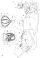
- Fig. 1 is a schematic, pictorial illustration of a medical system 20, in accordance with an example of the present disclosure.
- the system 20 includes a catheter 40' configured to be inserted into a body part (e.g., a chamber of a heart 26) of a living subject (e.g., a patient 28).
- a physician 30 navigates the catheter 40' (for example, a basket catheter produced by Biosense Webster, Inc. of Irvine, CA, USA), seen in detail inset 45, to a target location in the heart 26 of the patient 28, by manipulating a deflectable segment of an insertion tube 22 of the catheter 40'.
- physician 30 uses catheter 40' to perform electro-anatomical mapping of a cardiac chamber.
- the catheter 40' includes a distal end 33.
- the distal end 33 of the catheter 40' includes an assembly 35 (e.g., a basket assembly as shown in Fig. 1 or a balloon assembly or any suitable distal end assembly, e.g., grid, flexible splines or a focal catheter) on which at least one (e.g., multiple) catheter electrode(s) 48 (only some labeled for the sake of simplicity) are disposed.
- the electrodes 48 are configured to contact tissue at respective locations with the chamber of the heart.
- Fig. 1 also shows another catheter 40" inserted into a chamber of the heart 26.
- the catheter 40" may be any suitable catheter, for example, a pacing catheter or an imaging catheter such as an ultrasound catheter or a focal catheter.
- the catheter 40" is connected via a cable 38 to a port 46 on a console 24.
- the console 24 includes other ports 46 for connecting other catheters to the console 24.
- the distal end 33 of the catheter 40' may comprise magnetic coil sensors 50A and 50B.
- the magnetic coil sensor 50A is shown in inset 45 at the distal edge of insertion tube 22 (i.e., at the proximal edge of basket assembly 35).
- Magnetic coil sensors 50A and 50B and electrodes 48 are connected by wires running through insertion tube 22 to various driver circuitries in console 24.
- system 20 comprises a magnetic-sensing sub-system.
- Patient 28 is placed in a magnetic field generated by a pad containing multiple magnetic field generator coils 42, which are driven by a magnetic sensing driver unit 43.
- the magnetic field generator coils 42 are configured to generate respective alternating magnetic fields, having respective different frequencies, into a region where a body-part (e.g., the heart 26) of a living subject (e.g., the patient 28) is located.
- the magnetic coil sensors 50A and 50B are configured to output electrical signals responsively to detecting the respective magnetic fields. The generated signals are transmitted to console 24 and become corresponding electrical inputs to processing circuitry 41.
- the processing circuitry 41 uses position-signals received from the electrodes 48 or body surface electrodes 49, and the magnetic sensor 50 to estimate a position of the assembly 35 inside a body part, such as inside a cardiac chamber. In some examples, the processing circuitry 41 correlates the position signals received from the electrodes 48, 49 with previously acquired magnetic location-calibrated position signals, to estimate the position of the assembly 35 inside the body part.
- the position coordinates of the electrodes 48 may be determined by the processing circuitry 41 based on, among other inputs, measured impedances, voltages or on proportions of currents distribution, between the electrodes 48 and the body surface electrodes 49.
- the method of position sensing using current distribution measurements and/or external magnetic fields is implemented in various medical applications, for example, in the Carto ® system, produced by Biosense Webster Inc. (Irvine, California), and is described in detail in U.S. Patents 5,391,199 , 6,690,963 , 6,484,118 , 6,239,724 , 6,618,612 , 6,332,089 , 7,756,576 , 7,869,865 , and 7,848,787 , in PCT Patent Publication WO 96/05768 , and in U.S. Patent Application Publications 2002/0065455 A1 , 2003/0120150 A1 and 2004/0068178 A1 .
- Processing circuitry 41 is further connected via a suitable front end and interface circuits 44, to receive signals from body surface-electrodes 49.
- Processing circuitry 41 is connected to surface-electrodes 49 by wires running through a cable 39 to the chest of patient 28.
- the catheter 40' includes a connector 47 disposed at the proximal end 29 of the insertion tube 22 for coupling with the processing circuitry 41 via one of the ports 46 of the console 24.
- processing circuitry 41 renders to a display 27, a representation 31 of at least a part of the catheter 40' and a body-part.
- Processing circuitry 41 is typically programmed in software and/or firmware to carry out the functions described herein.
- the software may be downloaded to the computer in electronic form, over a network, for example, or it may, alternatively or additionally, be provided and/or stored on non-transitory tangible media, such as magnetic, optical, or electronic memory.
- the system 20 may also include a memory 51 used by the processing circuitry 41.
- Fig. 1 shows only elements related to the disclosed techniques for the sake of simplicity and clarity.
- System 20 typically comprises additional modules and elements that are not directly related to the disclosed techniques, and thus are intentionally omitted from Fig. 1 and from the corresponding description.
- the elements of system 20 and the methods described herein may be further applied, for example, to control an ablation of tissue of heart 26.
- Fig. 2 is a schematic view of different cables 38, catheters 40 configured to be inserted into a body part of a living subject, and console ports 46 in the system 20 of Fig. 1 .
- the catheters 40 may include a respective electrical connector at their proximal ends with which to couple the catheters 40 via respective ones of the cables 38 with the ports 46.
- the catheters 40 may have respective electrical channel profiles. Some of the electrical channel profiles of the catheters 40 may be the same, and in some cases the electrical channel profiles of the catheters 40 may all be different.
- An electrical channel profile of a catheter defines the total number of electrical connections to/from the catheter via the catheter electrical connector and the arrangement of those electrical connections in the catheter electrical connector (e.g., an arrangement of the pins of the catheter electrical connector).
- the electrical channel profile of the catheter may also include the number of sub-categories of electrical channels and their arrangement among the pins.
- the electrical channel profile of a catheter may include X electrogram electrical connections (e.g., to X corresponding mapping electrodes of the catheter), Y ablation electrical connections (e.g., to Y ablation electrodes of the catheter), and Z position signal electrical connections to carry signals to/from position signals in the catheter, and so on.
- the electrical channels may also include electrical connections to carry signals to imaging modalities such as ultrasound.
- Each of X, Y and Z represents an integer number, e.g., a number between 1-500.
- the console 24 includes the ports 46 configured to be coupled with the catheters 40 via respective ones of the cables 38.
- the ports 46 may have respective electrical channel profiles. Some of the electrical channel profiles of the ports 46 may be the same, and in some cases the electrical channel profiles of the ports 46 may all be different.
- An electrical channel profile of a port defines the total number of electrical connections through the port and the arrangement of those electrical connections in the port (e.g., an arrangement of the pins of the port).
- the electrical channel profile of the port may also include the number of sub-categories of electrical channels and their arrangement among the pins.
- the electrical channel profile of the port may include X electrogram electrical connections (e.g., connected to electrogram processing circuitry in the console 24), Y ablation electrical connections (e.g., connected to ablation power generator(s) in the console 24), and Z position signal electrical connections (e.g., connected to position tracking circuitry in the console 24), and so on.
- the electrical channels may also include electrical connections to carry signals to imaging processing circuitry in the console 24.
- the ports 46 are provided with indications which are static (i.e., the indications do not change), for example, using colors, shapes, names and/or numbers.
- the ports 46 shown in Fig. 2 are labeled 1-5.
- Each of the cables 38 includes two respective electrical connectors 47 and 47', one connector 47 to couple with one or more of the ports 46 and another connector 47' to couple with one or more of the catheters 40.
- the cables 38 may have respective electrical channel profiles.
- An electrical channel profile of a cable defines the total number of electrical connections through the cable and the arrangement of those electrical connections in the electrical connectors of the cable (e.g., an arrangement of the pins of the electrical connectors).
- the electrical channel profile of the cable may also include the number of sub-categories of electrical channels and their arrangement among the pins of the respective electrical connectors.
- the electrical channel profile of the cable may include X electrogram electrical connections (e.g., for connection to electrogram channels of the catheters 40 and ports 46), Y ablation electrical connections (e.g., for connection to ablation channels of the catheters 40 and ports 46), and Z position signal electrical connections (e.g., for connection to position signal channels of the catheters 40 and ports 46), and so on.
- X electrogram electrical connections e.g., for connection to electrogram channels of the catheters 40 and ports 46
- Y ablation electrical connections e.g., for connection to ablation channels of the catheters 40 and ports 46
- Z position signal electrical connections e.g., for connection to position signal channels of the catheters 40 and ports 46
- the cables 38 and/or cable packaging 66 may be provided with indications (e.g., labels), for example, using colors, shapes, names and/or numbers.
- indications e.g., labels
- one cable 38 and/or its connectors may be green, or include a green band, and/or include a green label on the cable packaging 66.
- the processing circuitry is configured to receive user input selecting at least one procedure type (e.g., mapping or ablation) to be performed during the medical procedure.
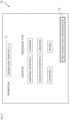
- the catheters 40 and optionally the procedure types may be selected using the user interface screen 70 rendered to the display 27 as shown in Fig. 4 .
- the processing circuitry 41 is configured to receive user input selecting a workflow template (input field 71) thereby selecting the catheters 40 to be used in a medical procedure.
- a workflow template input field 71
- the processing circuitry 41 is configured to receive user input selecting a workflow template (input field 71) thereby selecting the catheters 40 to be used in a medical procedure.
- one or more physicians may save different workflow templates including the catheters 40 used in the workflow and optionally associated procedure types performed by each catheter 40.
- the selected workflow template may be retrieved from the memory 51 thereby selecting the catheters 40 (and procedure types) to be used.
- the catheters 40 and optionally the procedure types to be performed in the selected workflow template are displayed on the display 27.
- the displayed catheters 40 and procedure types may be changed by the physician 30.
- the physician 30 may select the "find connection configuration" button 72 for the processing circuitry 41 to proceed to find the connection configuration of the selected catheters 40 with the ports 46.
- the processing circuitry 41 is configured to set at least one of the respective electrical channel profiles of the selected catheter(s) 40 responsively to the corresponding procedure type(s) (block 104). For example, if one of the selected catheters 40 has mapping electrodes and ablation electrodes, and the procedure type selected for that catheter is mapping, the ablation channels of that catheter do not need to be coupled with the ablation circuitry in the console 24 and therefore, the ablation channels of that catheter may be ignored when finding the connection configuration.
- the processing circuitry 41 is configured to match the respective electrical channel profiles of the respective selected catheters 40 to the respective electrical channel profiles of respective ones of the ports 46 and the respective electrical channel profiles of respective ones of the cables 38 (block 106). In some examples, the processing circuitry 41 is configured to match respective electrogram channel sets (and/or ablation channel sets and/or position signal channel sets) of the respective selected catheters 40 to respective electrogram channel sets (and/or ablation channel sets and/or position signal channel sets) of the respective ports 46 and the respective electrogram channel sets (and/or ablation channel sets and/or position signal channel sets) of respective ones of the cables 38.
- connection configurations of different combination of catheters 40 with the ports 46 via different cables 38 may be pre-computed and saved so that when a given catheter combination is selected, the pre-computed optimal connection configuration may be retrieved from the memory 51.
- Fig. 5 is a flowchart 150 including steps in a catheter matching sub-method of the method of Fig. 3 .
- the processing circuitry 41 is configured to select from the selected catheters 40 (in the selection received in the step of block 102 ( Fig. 3 )), the catheter 40 with the largest electrical channel profile (e.g., the largest number of electrical connections or the largest number of electrogram channels etc.) (block 152).
- the processing circuitry 41 is configured to compare the electrical channel profile with the electrical channel profiles of the unassigned ports 46 optionally starting with the port 46 having the smallest electrical channel profile (block 154).
- the processing circuitry 41 is configured to assign the selected catheters 40 to the matching port 46 in the connection configuration (block 156).
- the processing circuitry 41 is configured to determine if there are more catheters 40 in the selection received in the step of block 102 ( Fig. 3 ) to be matched using the above steps. If there are no more catheters 40 in the received selection to be matched using the above steps, the process ends (block 160). If there is one or more catheters 40 in the received selected to be matched using the above steps, the processing circuitry 41 is configured to select the next catheter 40 having the next largest electrical channel profile (block 162) and the steps of blocks 154-158 are repeated with the newly selected catheter. The above steps may also be used to find the correct cables 38 for the found catheter-port pairs.
- the processing circuitry 41 is configured to find the connection configuration with which to couple the respective selected catheters 40 with ones of the ports 46, responsively to (matching) the respective electrical channel profiles of the respective selected catheters 40 and the respective electrical channel profiles of the ports 46 (block 110). In some examples, the processing circuitry 41 is configured to find the connection configuration responsively to matching, for example, using the matching step of block 106 or the matching method described with reference to Fig. 5 . In some examples, the processing circuitry 41 is configured to find the connection configuration with which to couple the respective selected catheters 40 with the ones of the ports 46 for the same time period during the medical procedure, responsively to (matching) the respective electrical channel profiles of the respective selected catheters 40 and the respective electrical channel profiles of the ports 46.
- the processing circuitry 41 is configured to find the connection configuration with which to couple the respective selected catheters 40 with ones of the ports 46 via respective cables 38, responsively to the respective electrical channel profiles of the respective selected catheters 40, the respective electrical channel profiles of the ports 46, and respective electrical channel profiles of the respective cables 38.
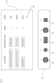
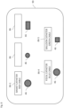
- Fig. 6 is a schematic view of a port panel 74 (in the console 24 of Fig. 1 ) and a user interface window 76 on display 27 showing a connection configuration 78 in the system 20 of Fig. 1 .
- the processing circuitry 41 is configured to render to the display 27 the connection configuration 78 comprising a mapping between the respective selected catheters 40 and respective indications of the ports 46 and the cables 38 (block 112).
- the ports 46 are provided with static (i.e., fixed) indications (e.g., labels), for example, using colors, shapes, names and/or numbers.
- the cables 38 and/or cable packaging 66 may also be labeled, for example, using colors, shapes, names and/or numbers.
- the ports are labeled 1-5, the cables 38 are labeled using colors, and the connection configuration 78 rendered to the display 27 lists the port number and cable/cable packaging color for each of the selected catheters 40.
- mapping catheter A e.g., a basket catheter
- ablation catheter B e.g., a balloon catheter
- catheter C e.g., a focal catheter
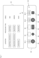
- Fig. 7 is a schematic view of an alternative port panel 80 and an alternative user interface screen 82 showing a connection configuration 84 in the system 20 of Fig. 1 .
- the system 20 may include respective port-displays 86 for the ports 46 with one port-display 86 per port 46.
- the processing circuitry 41 is configured to render to at least some of the port displays 86 respective indications of the respective cables 38 (e.g., by color, name, number or picture) that should be connected to respective ports 46 responsively to the connection configuration 84.
- the processing circuitry 41 is also configured to render to the display 27 indications of the respective cable 38 that should be connected to each catheter 40. For example, as shown in Fig.
- the user interface screen 82 rendered on the display 27 indicates that mapping catheter A should be connected using the red cable, ablation catheter B should be connected using the green cable, and catheter C should be connected using the blue cable.
- the port displays 86-1, 86-5, 86-4, of ports 1, 5, and 4 display "red", “green”, and “blue” using text, respectively, indicating how the cables 38 that should be connected to the ports 46.
- the port-displays 86 may indicate the colors of the cables to be connected using a colored shape or colored text.
- the port-displays 86 may be configured as ring-shaped liquid crystal displays (LCD) displays (controlled by software) that change color according to the cables to be attached to the respective ports 46.
- LCD liquid crystal displays
Landscapes
- Health & Medical Sciences (AREA)
- Life Sciences & Earth Sciences (AREA)
- Engineering & Computer Science (AREA)
- Surgery (AREA)
- General Health & Medical Sciences (AREA)
- Animal Behavior & Ethology (AREA)
- Veterinary Medicine (AREA)
- Public Health (AREA)
- Biomedical Technology (AREA)
- Heart & Thoracic Surgery (AREA)
- Molecular Biology (AREA)
- Medical Informatics (AREA)
- Physics & Mathematics (AREA)
- Biophysics (AREA)
- Nuclear Medicine, Radiotherapy & Molecular Imaging (AREA)
- Pathology (AREA)
- Cardiology (AREA)
- Otolaryngology (AREA)
- Plasma & Fusion (AREA)
- Physiology (AREA)
- Human Computer Interaction (AREA)
- Robotics (AREA)
- Pulmonology (AREA)
- Anesthesiology (AREA)
- Hematology (AREA)
- Surgical Instruments (AREA)
- External Artificial Organs (AREA)
- Measurement And Recording Of Electrical Phenomena And Electrical Characteristics Of The Living Body (AREA)
- Infusion, Injection, And Reservoir Apparatuses (AREA)
- Media Introduction/Drainage Providing Device (AREA)
Claims (13)
- Medizinisches System (20), umfassend:eine Anzeige (27);eine Konsole (24), die eine Vielzahl von Anschlüssen (46) umfasst, die so konfiguriert sind, dass sie über entsprechende Kabel (38) mit Kathetern (40) verbunden werden können, wobei die Katheter (40) entsprechende erste elektrische Kanalprofile aufweisen und die Anschlüsse (46) entsprechende zweite elektrische Kanalprofile aufweisen; undVerarbeitungsschaltlogik (41) konfiguriert zum:Empfangen von Benutzereingaben zum Auswählen der jeweiligen Katheter (40), die in einem medizinischen Verfahren verwendet werden sollen;Ermitteln einer Verbindungskonfiguration, mit der die jeweiligen Katheter (40) über die jeweiligen Kabel (38) mit einem der Anschlüsse (46) gekoppelt werden können, und zwar als Reaktion auf die jeweiligen ersten elektrischen Kanalprofile der jeweiligen Katheter (40), die jeweiligen zweiten elektrischen Kanalprofile der Anschlüsse (46) und die jeweiligen elektrischen Kanalprofile der jeweiligen Kabel (38); undWiedergeben der Verbindungskonfiguration auf der Anzeige (27), wobeidie Kabel (38) und die Anschlüsse (46) mit Hinweisen versehen sind; unddie Verarbeitungsschaltung (41) dazu konfiguriert ist, auf der Anzeige (27) die Verbindungskonfiguration wiederzugeben, die eine Zuordnung zwischen den jeweiligen Kathetern (40) und den jeweiligen Hinweisen umfasst.
- System (20) nach Anspruch 1, wobei die Verarbeitungsschaltung (41) dazu konfiguriert ist, eine Benutzereingabe zu empfangen, die eine Arbeitsablaufvorlage auswählt und dadurch die jeweiligen Katheter (40) auswählt, die in einem medizinischen Verfahren verwendet werden sollen.
- System (20) nach Anspruch 1 oder Anspruch 2, wobei die Verarbeitungsschaltung (41) dazu konfiguriert ist, die Verbindungskonfiguration zu ermitteln, mit der die jeweiligen Katheter (40) mit den Anschlüssen (46) für einen gleichen Zeitraum während des medizinischen Verfahrens gekoppelt werden, und zwar als Reaktion auf die jeweiligen ersten elektrischen Kanalprofile der jeweiligen Katheter (40) und die jeweiligen zweiten elektrischen Kanalprofile der Anschlüsse (46).
- System (20) nach einem der vorstehenden Ansprüche, wobei die Anzeige (27) jeweilige Anschlussanzeigen (86) für die Anschlüsse (46) einschließt, wobei die Verarbeitungsschaltung (41) so konfiguriert ist, dass sie an einer der Anschlussanzeigen Hinweise der jeweiligen Katheter (40) wiedergibt, die als Reaktion auf die Verbindungskonfiguration mit den jeweiligen Anschlüssen (46) verbunden werden sollen.
- System (20) nach Anspruch 1, wobei die Hinweise statisch sind.
- System (20) nach Anspruch 1, wobei die Anzeige jeweilige Anschlussanzeigen (86) für die Anschlüsse (46) einschließt, wobei die Verarbeitungsschaltung (41) so konfiguriert ist, dass sie als Reaktion auf die Verbindungskonfiguration den jeweiligen Anschlussanzeigen die jeweiligen Hinweise der jeweiligen Kabel (38) wiedergibt, die mit den jeweiligen Anschlüssen (46) verbunden werden sollen.
- System (20) nach einem der vorstehenden Ansprüche, wobei die Verarbeitungsschaltung (41) konfiguriert ist zum:Abgleichen der jeweiligen ersten elektrischen Kanalprofile der jeweiligen Katheter (40) mit den jeweiligen zweiten elektrischen Kanalprofilen der jeweiligen Anschlüsse (46); undErmitteln der passenden Verbindungskonfiguration entsprechend des Abgleichs.
- System (20) nach Anspruch 7, wobei die Verarbeitungsschaltung (41) dazu konfiguriert ist, jeweilige Elektrogrammkanalsätze der jeweiligen Katheter (40) mit jeweiligen Elektrogrammkanalsätzen der jeweiligen Anschlüsse (46) abzugleichen.
- System (20) nach einem der vorstehenden Ansprüche, wobei die Verarbeitungsschaltung (41) konfiguriert ist zum:Empfangen einer Benutzereingabe zum Auswählen von mindestens einem Verfahrenstyp, der während des medizinischen Verfahrens durchgeführt werden soll; undErmitteln der Verbindungskonfiguration, mit der die jeweiligen Katheter (40) mit einem der Anschlüsse (46) gekoppelt werden, und zwar als Reaktion auf die jeweiligen ersten elektrischen Kanalprofile der jeweiligen Katheter (40), die jeweiligen zweiten elektrischen Kanalprofile der Anschlüsse (46) und den mindestens einen Verfahrenstyp.
- System (20) nach Anspruch 9, wobei die Verarbeitungsschaltung (41) dazu konfiguriert ist, eine Reihenfolge zu priorisieren, in der die jeweiligen Katheter (40) als Reaktion auf den mindestens einen Verfahrenstyp mit der Konsole (24) gekoppelt werden.
- System (20) nach Anspruch 9 oder Anspruch 10, wobei die Verarbeitungsschaltung (41) dazu konfiguriert ist, mindestens eines der jeweiligen ersten elektrischen Kanalprofile als Reaktion auf den mindestens einen Verfahrenstyp einzustellen.
- Computerprogramm, umfassend Anweisungen, die, wenn das Programm durch die Verarbeitungsschaltung (41) ausgeführt wird, die Verarbeitungsschaltung (41) veranlassen zum:Empfangen von Benutzereingaben zum Auswählen entsprechender Katheter (40) zur Verwendung in einem medizinischen Verfahren, wobei die Katheter (40) so konfiguriert sind, dass sie über entsprechende Kabel (38) mit einer Vielzahl von Anschlüssen (46) verbunden werden können, wobei die Katheter (40) entsprechende erste elektrische Kanalprofile aufweisen und die Anschlüsse (46) entsprechende zweite elektrische Kanalprofile aufweisen;Ermitteln einer Verbindungskonfiguration, mit der die jeweiligen Katheter (40) über die jeweiligen Kabel (38) mit einem der Anschlüsse (46) gekoppelt werden können, und zwar als Reaktion auf die jeweiligen ersten elektrischen Kanalprofile der jeweiligen Katheter (40), die jeweiligen zweiten elektrischen Kanalprofile der Anschlüsse (46) und die jeweiligen elektrischen Kanalprofile der jeweiligen Kabel (38); undWiedergeben der Verbindungskonfiguration auf einer Anzeige (27),wobei die Kabel (38) und die Anschlüsse (46) mit Hinweisen versehen sind; und wobeidie Verarbeitungsschaltung (41) veranlasst wird, auf der Anzeige (27) die Verbindungskonfiguration wiederzugeben, die eine Zuordnung zwischen den jeweiligen Kathetern (40) und den jeweiligen Hinweisen umfasst.
- Computerlesbarer Datenträger, auf dem das Computerprogramm nach Anspruch 12 gespeichert ist.
Applications Claiming Priority (1)
| Application Number | Priority Date | Filing Date | Title |
|---|---|---|---|
| US17/542,789 US12336823B2 (en) | 2021-12-06 | 2021-12-06 | Catheter connection configuration system |
Publications (3)
| Publication Number | Publication Date |
|---|---|
| EP4190256A1 EP4190256A1 (de) | 2023-06-07 |
| EP4190256B1 true EP4190256B1 (de) | 2024-08-21 |
| EP4190256C0 EP4190256C0 (de) | 2024-08-21 |
Family
ID=84389268
Family Applications (1)
| Application Number | Title | Priority Date | Filing Date |
|---|---|---|---|
| EP22211476.1A Active EP4190256B1 (de) | 2021-12-06 | 2022-12-05 | Katheterverbindungskonfigurationssystem |
Country Status (5)
| Country | Link |
|---|---|
| US (1) | US12336823B2 (de) |
| EP (1) | EP4190256B1 (de) |
| JP (1) | JP2023084121A (de) |
| CN (1) | CN116211437A (de) |
| IL (1) | IL298627B2 (de) |
Families Citing this family (1)
| Publication number | Priority date | Publication date | Assignee | Title |
|---|---|---|---|---|
| CN120091944A (zh) | 2022-10-24 | 2025-06-03 | 软银集团股份有限公司 | 信息处理装置、车辆、信息处理方法以及信息处理程序 |
Family Cites Families (24)
| Publication number | Priority date | Publication date | Assignee | Title |
|---|---|---|---|---|
| US5342356A (en) | 1992-12-02 | 1994-08-30 | Ellman Alan G | Electrical coupling unit for electrosurgery |
| US5391199A (en) | 1993-07-20 | 1995-02-21 | Biosense, Inc. | Apparatus and method for treating cardiac arrhythmias |
| WO1996005768A1 (en) | 1994-08-19 | 1996-02-29 | Biosense, Inc. | Medical diagnosis, treatment and imaging systems |
| JPH10503673A (ja) | 1994-06-24 | 1998-04-07 | アドバンスト・カーディオバスキュラー・システムズ・インコーポレイテッド | 再使用できる近位体を有するカテーテル |
| US6690963B2 (en) | 1995-01-24 | 2004-02-10 | Biosense, Inc. | System for determining the location and orientation of an invasive medical instrument |
| DE69726576T2 (de) | 1996-02-15 | 2004-10-14 | Biosense, Inc., Miami | Probe zur Ortsmarkierung |
| IL125761A (en) | 1996-02-15 | 2005-05-17 | Biosense Inc | Independently positionable transducers for location system |
| US6239724B1 (en) | 1997-12-30 | 2001-05-29 | Remon Medical Technologies, Ltd. | System and method for telemetrically providing intrabody spatial position |
| US6508809B1 (en) | 1999-10-29 | 2003-01-21 | Karl Storz Gmbh & Co. Kg | Device for connecting a plurality of apparatus and instruments of a medico-technical system |
| US20020006455A1 (en) | 2000-07-10 | 2002-01-17 | Levine Michael L. | Baby food selection system and method |
| US6484118B1 (en) | 2000-07-20 | 2002-11-19 | Biosense, Inc. | Electromagnetic position single axis system |
| US7729742B2 (en) | 2001-12-21 | 2010-06-01 | Biosense, Inc. | Wireless position sensor |
| US20040068178A1 (en) | 2002-09-17 | 2004-04-08 | Assaf Govari | High-gradient recursive locating system |
| US7869865B2 (en) | 2005-01-07 | 2011-01-11 | Biosense Webster, Inc. | Current-based position sensing |
| US7848787B2 (en) | 2005-07-08 | 2010-12-07 | Biosense Webster, Inc. | Relative impedance measurement |
| US7756576B2 (en) | 2005-08-26 | 2010-07-13 | Biosense Webster, Inc. | Position sensing and detection of skin impedance |
| US20110125149A1 (en) * | 2007-02-06 | 2011-05-26 | Rizk El-Galley | Universal surgical function control system |
| US8641704B2 (en) | 2007-05-11 | 2014-02-04 | Medtronic Ablation Frontiers Llc | Ablation therapy system and method for treating continuous atrial fibrillation |
| DE102007061483A1 (de) | 2007-12-20 | 2009-07-02 | Erbe Elektromedizin Gmbh | Chirurgiegerätesteckersystem |
| DE102011083957B4 (de) * | 2011-10-04 | 2018-12-27 | Siemens Healthcare Gmbh | Gerätesteuerung mit zuschaltbaren Touch-User-Interfaces |
| US20140171785A1 (en) * | 2012-12-17 | 2014-06-19 | Biosense Webster (Israel), Ltd. | Recognizing which instrument is currently active |
| JP6218681B2 (ja) * | 2014-06-17 | 2017-10-25 | オリンパス株式会社 | 医療システムの設定方法 |
| US10987091B2 (en) * | 2016-05-17 | 2021-04-27 | Biosense Webster (Israel) Ltd. | System and method for catheter connections |
| US20180235509A1 (en) | 2017-02-22 | 2018-08-23 | Biosense Webster (Israel) Ltd. | Catheter identification system and method |
-
2021
- 2021-12-06 US US17/542,789 patent/US12336823B2/en active Active
-
2022
- 2022-11-28 IL IL298627A patent/IL298627B2/en unknown
- 2022-12-05 JP JP2022194048A patent/JP2023084121A/ja active Pending
- 2022-12-05 EP EP22211476.1A patent/EP4190256B1/de active Active
- 2022-12-06 CN CN202211554816.XA patent/CN116211437A/zh active Pending
Also Published As
| Publication number | Publication date |
|---|---|
| IL298627A (en) | 2023-07-01 |
| CN116211437A (zh) | 2023-06-06 |
| EP4190256A1 (de) | 2023-06-07 |
| US20230172512A1 (en) | 2023-06-08 |
| IL298627B2 (en) | 2025-09-01 |
| JP2023084121A (ja) | 2023-06-16 |
| EP4190256C0 (de) | 2024-08-21 |
| IL298627B1 (en) | 2025-05-01 |
| US12336823B2 (en) | 2025-06-24 |
Similar Documents
| Publication | Publication Date | Title |
|---|---|---|
| KR102889813B1 (ko) | 심장내 심전도 제시 | |
| EP3834730B1 (de) | Automatisierte graphische darstellung von elektrophysiologischen parametern | |
| EP3838151B1 (de) | Selektive graphische darstellung von elektrophysiologischen parametern | |
| EP2875779A1 (de) | Flexibler mehrarmiger Diagnosekatheter | |
| JP2019010513A (ja) | リアルタイム3次元(3d)心臓撮像におけるガラス状態ビューのためのシステム及び方法 | |
| KR102864863B1 (ko) | 전기해부학적 맵 재주석화 | |
| EP4062833A1 (de) | Visualisierung von mehreren überlagerten parametern auf einer anatomischen karte | |
| EP4190256B1 (de) | Katheterverbindungskonfigurationssystem | |
| EP4101383A1 (de) | Bipolare elektrodenpaarauswahl | |
| CN115500933A (zh) | 自动解剖特征识别和标测图分割 | |
| EP4525758A1 (de) | Visualisierung eines qualitätsindexes zur anzeige der ablationsstabilität an einer ablationsstelle | |
| US20240050017A1 (en) | Visualizing and Clustering Multiple Electrodes of a High-Definition Catheter Projected on Tissue Surface | |
| CN120918776A (zh) | 利用图形用户界面的心脏标测图调光 | |
| KR20210045315A (ko) | 로컬 렌더링 기반 멀티 모달리티 서브세트 제시 |
Legal Events
| Date | Code | Title | Description |
|---|---|---|---|
| PUAI | Public reference made under article 153(3) epc to a published international application that has entered the european phase |
Free format text: ORIGINAL CODE: 0009012 |
|
| STAA | Information on the status of an ep patent application or granted ep patent |
Free format text: STATUS: THE APPLICATION HAS BEEN PUBLISHED |
|
| AK | Designated contracting states |
Kind code of ref document: A1 Designated state(s): AL AT BE BG CH CY CZ DE DK EE ES FI FR GB GR HR HU IE IS IT LI LT LU LV MC ME MK MT NL NO PL PT RO RS SE SI SK SM TR |
|
| STAA | Information on the status of an ep patent application or granted ep patent |
Free format text: STATUS: REQUEST FOR EXAMINATION WAS MADE |
|
| 17P | Request for examination filed |
Effective date: 20231201 |
|
| RBV | Designated contracting states (corrected) |
Designated state(s): AL AT BE BG CH CY CZ DE DK EE ES FI FR GB GR HR HU IE IS IT LI LT LU LV MC ME MK MT NL NO PL PT RO RS SE SI SK SM TR |
|
| GRAP | Despatch of communication of intention to grant a patent |
Free format text: ORIGINAL CODE: EPIDOSNIGR1 |
|
| STAA | Information on the status of an ep patent application or granted ep patent |
Free format text: STATUS: GRANT OF PATENT IS INTENDED |
|
| RIC1 | Information provided on ipc code assigned before grant |
Ipc: A61B 34/20 20160101ALN20240408BHEP Ipc: A61B 17/00 20060101ALN20240408BHEP Ipc: A61B 90/00 20160101ALN20240408BHEP Ipc: A61B 18/00 20060101ALN20240408BHEP Ipc: A61B 34/00 20160101ALN20240408BHEP Ipc: A61B 18/14 20060101ALN20240408BHEP Ipc: A61B 18/12 20060101AFI20240408BHEP |
|
| INTG | Intention to grant announced |
Effective date: 20240425 |
|
| GRAS | Grant fee paid |
Free format text: ORIGINAL CODE: EPIDOSNIGR3 |
|
| GRAA | (expected) grant |
Free format text: ORIGINAL CODE: 0009210 |
|
| STAA | Information on the status of an ep patent application or granted ep patent |
Free format text: STATUS: THE PATENT HAS BEEN GRANTED |
|
| AK | Designated contracting states |
Kind code of ref document: B1 Designated state(s): AL AT BE BG CH CY CZ DE DK EE ES FI FR GB GR HR HU IE IS IT LI LT LU LV MC ME MK MT NL NO PL PT RO RS SE SI SK SM TR |
|
| REG | Reference to a national code |
Ref country code: GB Ref legal event code: FG4D |
|
| REG | Reference to a national code |
Ref country code: CH Ref legal event code: EP |
|
| REG | Reference to a national code |
Ref country code: IE Ref legal event code: FG4D |
|
| REG | Reference to a national code |
Ref country code: DE Ref legal event code: R096 Ref document number: 602022005492 Country of ref document: DE |
|
| U01 | Request for unitary effect filed |
Effective date: 20240918 |
|
| U07 | Unitary effect registered |
Designated state(s): AT BE BG DE DK EE FI FR IT LT LU LV MT NL PT RO SE SI Effective date: 20241008 |
|
| U20 | Renewal fee for the european patent with unitary effect paid |
Year of fee payment: 3 Effective date: 20241107 |
|
| PG25 | Lapsed in a contracting state [announced via postgrant information from national office to epo] |
Ref country code: NO Free format text: LAPSE BECAUSE OF FAILURE TO SUBMIT A TRANSLATION OF THE DESCRIPTION OR TO PAY THE FEE WITHIN THE PRESCRIBED TIME-LIMIT Effective date: 20241121 |
|
| PG25 | Lapsed in a contracting state [announced via postgrant information from national office to epo] |
Ref country code: GR Free format text: LAPSE BECAUSE OF FAILURE TO SUBMIT A TRANSLATION OF THE DESCRIPTION OR TO PAY THE FEE WITHIN THE PRESCRIBED TIME-LIMIT Effective date: 20241122 Ref country code: PL Free format text: LAPSE BECAUSE OF FAILURE TO SUBMIT A TRANSLATION OF THE DESCRIPTION OR TO PAY THE FEE WITHIN THE PRESCRIBED TIME-LIMIT Effective date: 20240821 |
|
| PG25 | Lapsed in a contracting state [announced via postgrant information from national office to epo] |
Ref country code: IS Free format text: LAPSE BECAUSE OF FAILURE TO SUBMIT A TRANSLATION OF THE DESCRIPTION OR TO PAY THE FEE WITHIN THE PRESCRIBED TIME-LIMIT Effective date: 20241221 |
|
| PG25 | Lapsed in a contracting state [announced via postgrant information from national office to epo] |
Ref country code: HR Free format text: LAPSE BECAUSE OF FAILURE TO SUBMIT A TRANSLATION OF THE DESCRIPTION OR TO PAY THE FEE WITHIN THE PRESCRIBED TIME-LIMIT Effective date: 20240821 |
|
| PG25 | Lapsed in a contracting state [announced via postgrant information from national office to epo] |
Ref country code: ES Free format text: LAPSE BECAUSE OF FAILURE TO SUBMIT A TRANSLATION OF THE DESCRIPTION OR TO PAY THE FEE WITHIN THE PRESCRIBED TIME-LIMIT Effective date: 20240821 Ref country code: RS Free format text: LAPSE BECAUSE OF FAILURE TO SUBMIT A TRANSLATION OF THE DESCRIPTION OR TO PAY THE FEE WITHIN THE PRESCRIBED TIME-LIMIT Effective date: 20241121 |
|
| PG25 | Lapsed in a contracting state [announced via postgrant information from national office to epo] |
Ref country code: RS Free format text: LAPSE BECAUSE OF FAILURE TO SUBMIT A TRANSLATION OF THE DESCRIPTION OR TO PAY THE FEE WITHIN THE PRESCRIBED TIME-LIMIT Effective date: 20241121 Ref country code: PL Free format text: LAPSE BECAUSE OF FAILURE TO SUBMIT A TRANSLATION OF THE DESCRIPTION OR TO PAY THE FEE WITHIN THE PRESCRIBED TIME-LIMIT Effective date: 20240821 Ref country code: NO Free format text: LAPSE BECAUSE OF FAILURE TO SUBMIT A TRANSLATION OF THE DESCRIPTION OR TO PAY THE FEE WITHIN THE PRESCRIBED TIME-LIMIT Effective date: 20241121 Ref country code: IS Free format text: LAPSE BECAUSE OF FAILURE TO SUBMIT A TRANSLATION OF THE DESCRIPTION OR TO PAY THE FEE WITHIN THE PRESCRIBED TIME-LIMIT Effective date: 20241221 Ref country code: HR Free format text: LAPSE BECAUSE OF FAILURE TO SUBMIT A TRANSLATION OF THE DESCRIPTION OR TO PAY THE FEE WITHIN THE PRESCRIBED TIME-LIMIT Effective date: 20240821 Ref country code: GR Free format text: LAPSE BECAUSE OF FAILURE TO SUBMIT A TRANSLATION OF THE DESCRIPTION OR TO PAY THE FEE WITHIN THE PRESCRIBED TIME-LIMIT Effective date: 20241122 Ref country code: ES Free format text: LAPSE BECAUSE OF FAILURE TO SUBMIT A TRANSLATION OF THE DESCRIPTION OR TO PAY THE FEE WITHIN THE PRESCRIBED TIME-LIMIT Effective date: 20240821 |
|
| PG25 | Lapsed in a contracting state [announced via postgrant information from national office to epo] |
Ref country code: SM Free format text: LAPSE BECAUSE OF FAILURE TO SUBMIT A TRANSLATION OF THE DESCRIPTION OR TO PAY THE FEE WITHIN THE PRESCRIBED TIME-LIMIT Effective date: 20240821 |
|
| PG25 | Lapsed in a contracting state [announced via postgrant information from national office to epo] |
Ref country code: CZ Free format text: LAPSE BECAUSE OF FAILURE TO SUBMIT A TRANSLATION OF THE DESCRIPTION OR TO PAY THE FEE WITHIN THE PRESCRIBED TIME-LIMIT Effective date: 20240821 |
|
| PG25 | Lapsed in a contracting state [announced via postgrant information from national office to epo] |
Ref country code: SK Free format text: LAPSE BECAUSE OF FAILURE TO SUBMIT A TRANSLATION OF THE DESCRIPTION OR TO PAY THE FEE WITHIN THE PRESCRIBED TIME-LIMIT Effective date: 20240821 |
|
| PLBE | No opposition filed within time limit |
Free format text: ORIGINAL CODE: 0009261 |
|
| STAA | Information on the status of an ep patent application or granted ep patent |
Free format text: STATUS: NO OPPOSITION FILED WITHIN TIME LIMIT |
|
| PG25 | Lapsed in a contracting state [announced via postgrant information from national office to epo] |
Ref country code: MC Free format text: LAPSE BECAUSE OF FAILURE TO SUBMIT A TRANSLATION OF THE DESCRIPTION OR TO PAY THE FEE WITHIN THE PRESCRIBED TIME-LIMIT Effective date: 20240821 |
|
| 26N | No opposition filed |
Effective date: 20250522 |
|
| PG25 | Lapsed in a contracting state [announced via postgrant information from national office to epo] |
Ref country code: IE Free format text: LAPSE BECAUSE OF NON-PAYMENT OF DUE FEES Effective date: 20241205 |
|
| U20 | Renewal fee for the european patent with unitary effect paid |
Year of fee payment: 4 Effective date: 20251110 |
|
| PG25 | Lapsed in a contracting state [announced via postgrant information from national office to epo] |
Ref country code: CY Free format text: LAPSE BECAUSE OF FAILURE TO SUBMIT A TRANSLATION OF THE DESCRIPTION OR TO PAY THE FEE WITHIN THE PRESCRIBED TIME-LIMIT; INVALID AB INITIO Effective date: 20221205 |