EP4190262B1 - Système de traitement par aiguille laser - Google Patents
Système de traitement par aiguille laser Download PDFInfo
- Publication number
- EP4190262B1 EP4190262B1 EP21849459.9A EP21849459A EP4190262B1 EP 4190262 B1 EP4190262 B1 EP 4190262B1 EP 21849459 A EP21849459 A EP 21849459A EP 4190262 B1 EP4190262 B1 EP 4190262B1
- Authority
- EP
- European Patent Office
- Prior art keywords
- needle
- laser beam
- unit
- circuit board
- lens
- Prior art date
- Legal status (The legal status is an assumption and is not a legal conclusion. Google has not performed a legal analysis and makes no representation as to the accuracy of the status listed.)
- Active
Links
Images


Classifications
-
- A—HUMAN NECESSITIES
- A61—MEDICAL OR VETERINARY SCIENCE; HYGIENE
- A61N—ELECTROTHERAPY; MAGNETOTHERAPY; RADIATION THERAPY; ULTRASOUND THERAPY
- A61N5/00—Radiation therapy
- A61N5/06—Radiation therapy using light
- A61N5/0613—Apparatus adapted for a specific treatment
- A61N5/0619—Acupuncture
-
- A—HUMAN NECESSITIES
- A61—MEDICAL OR VETERINARY SCIENCE; HYGIENE
- A61B—DIAGNOSIS; SURGERY; IDENTIFICATION
- A61B18/00—Surgical instruments, devices or methods for transferring non-mechanical forms of energy to or from the body
- A61B18/18—Surgical instruments, devices or methods for transferring non-mechanical forms of energy to or from the body by applying electromagnetic radiation, e.g. microwaves
- A61B18/20—Surgical instruments, devices or methods for transferring non-mechanical forms of energy to or from the body by applying electromagnetic radiation, e.g. microwaves using laser
- A61B18/203—Surgical instruments, devices or methods for transferring non-mechanical forms of energy to or from the body by applying electromagnetic radiation, e.g. microwaves using laser applying laser energy to the outside of the body
-
- A—HUMAN NECESSITIES
- A61—MEDICAL OR VETERINARY SCIENCE; HYGIENE
- A61N—ELECTROTHERAPY; MAGNETOTHERAPY; RADIATION THERAPY; ULTRASOUND THERAPY
- A61N5/00—Radiation therapy
- A61N5/06—Radiation therapy using light
- A61N5/0601—Apparatus for use inside the body
-
- A—HUMAN NECESSITIES
- A61—MEDICAL OR VETERINARY SCIENCE; HYGIENE
- A61N—ELECTROTHERAPY; MAGNETOTHERAPY; RADIATION THERAPY; ULTRASOUND THERAPY
- A61N5/00—Radiation therapy
- A61N5/06—Radiation therapy using light
- A61N5/0613—Apparatus adapted for a specific treatment
- A61N5/0616—Skin treatment other than tanning
-
- A—HUMAN NECESSITIES
- A61—MEDICAL OR VETERINARY SCIENCE; HYGIENE
- A61N—ELECTROTHERAPY; MAGNETOTHERAPY; RADIATION THERAPY; ULTRASOUND THERAPY
- A61N5/00—Radiation therapy
- A61N5/06—Radiation therapy using light
- A61N5/067—Radiation therapy using light using laser light
-
- A—HUMAN NECESSITIES
- A61—MEDICAL OR VETERINARY SCIENCE; HYGIENE
- A61B—DIAGNOSIS; SURGERY; IDENTIFICATION
- A61B18/00—Surgical instruments, devices or methods for transferring non-mechanical forms of energy to or from the body
- A61B2018/00315—Surgical instruments, devices or methods for transferring non-mechanical forms of energy to or from the body for treatment of particular body parts
- A61B2018/00452—Skin
- A61B2018/00458—Deeper parts of the skin, e.g. treatment of vascular disorders or port wine stains
-
- A—HUMAN NECESSITIES
- A61—MEDICAL OR VETERINARY SCIENCE; HYGIENE
- A61B—DIAGNOSIS; SURGERY; IDENTIFICATION
- A61B18/00—Surgical instruments, devices or methods for transferring non-mechanical forms of energy to or from the body
- A61B18/18—Surgical instruments, devices or methods for transferring non-mechanical forms of energy to or from the body by applying electromagnetic radiation, e.g. microwaves
- A61B18/20—Surgical instruments, devices or methods for transferring non-mechanical forms of energy to or from the body by applying electromagnetic radiation, e.g. microwaves using laser
- A61B2018/2005—Surgical instruments, devices or methods for transferring non-mechanical forms of energy to or from the body by applying electromagnetic radiation, e.g. microwaves using laser with beam delivery through an interstitially insertable device, e.g. needle
-
- A—HUMAN NECESSITIES
- A61—MEDICAL OR VETERINARY SCIENCE; HYGIENE
- A61B—DIAGNOSIS; SURGERY; IDENTIFICATION
- A61B18/00—Surgical instruments, devices or methods for transferring non-mechanical forms of energy to or from the body
- A61B18/18—Surgical instruments, devices or methods for transferring non-mechanical forms of energy to or from the body by applying electromagnetic radiation, e.g. microwaves
- A61B18/20—Surgical instruments, devices or methods for transferring non-mechanical forms of energy to or from the body by applying electromagnetic radiation, e.g. microwaves using laser
- A61B2018/2035—Beam shaping or redirecting; Optical components therefor
- A61B2018/20553—Beam shaping or redirecting; Optical components therefor with special lens or reflector arrangement
-
- A—HUMAN NECESSITIES
- A61—MEDICAL OR VETERINARY SCIENCE; HYGIENE
- A61B—DIAGNOSIS; SURGERY; IDENTIFICATION
- A61B18/00—Surgical instruments, devices or methods for transferring non-mechanical forms of energy to or from the body
- A61B18/18—Surgical instruments, devices or methods for transferring non-mechanical forms of energy to or from the body by applying electromagnetic radiation, e.g. microwaves
- A61B18/20—Surgical instruments, devices or methods for transferring non-mechanical forms of energy to or from the body by applying electromagnetic radiation, e.g. microwaves using laser
- A61B2018/208—Surgical instruments, devices or methods for transferring non-mechanical forms of energy to or from the body by applying electromagnetic radiation, e.g. microwaves using laser with multiple treatment beams not sharing a common path, e.g. non-axial or parallel
-
- A—HUMAN NECESSITIES
- A61—MEDICAL OR VETERINARY SCIENCE; HYGIENE
- A61N—ELECTROTHERAPY; MAGNETOTHERAPY; RADIATION THERAPY; ULTRASOUND THERAPY
- A61N5/00—Radiation therapy
- A61N5/06—Radiation therapy using light
- A61N5/0601—Apparatus for use inside the body
- A61N2005/0612—Apparatus for use inside the body using probes penetrating tissue; interstitial probes
-
- A—HUMAN NECESSITIES
- A61—MEDICAL OR VETERINARY SCIENCE; HYGIENE
- A61N—ELECTROTHERAPY; MAGNETOTHERAPY; RADIATION THERAPY; ULTRASOUND THERAPY
- A61N5/00—Radiation therapy
- A61N5/06—Radiation therapy using light
- A61N2005/063—Radiation therapy using light comprising light transmitting means, e.g. optical fibres
-
- A—HUMAN NECESSITIES
- A61—MEDICAL OR VETERINARY SCIENCE; HYGIENE
- A61N—ELECTROTHERAPY; MAGNETOTHERAPY; RADIATION THERAPY; ULTRASOUND THERAPY
- A61N5/00—Radiation therapy
- A61N5/06—Radiation therapy using light
- A61N2005/0658—Radiation therapy using light characterised by the wavelength of light used
- A61N2005/0659—Radiation therapy using light characterised by the wavelength of light used infrared
- A61N2005/066—Radiation therapy using light characterised by the wavelength of light used infrared far infrared
-
- A—HUMAN NECESSITIES
- A61—MEDICAL OR VETERINARY SCIENCE; HYGIENE
- A61N—ELECTROTHERAPY; MAGNETOTHERAPY; RADIATION THERAPY; ULTRASOUND THERAPY
- A61N5/00—Radiation therapy
- A61N5/06—Radiation therapy using light
- A61N2005/0664—Details
Definitions
- the present invention relates to a needle laser treatment system.
- treatment methods using electric acupuncture, magnetic field (or magnet) acupuncture, infrared acupuncture, ultrasonic acupuncture, or the like by means of electricity, magnetic fields, infrared rays, laser beams, ultrasounds, or the like as a treatment means are used.
- These treatment methods are non-invasive methods that can obtain stimulating effects by applying electric current, magnetic fields, infrared rays, ultrasonic waves, or the like to a lesion.
- the treatment methods using the conventional electric acupuncture, magnetic acupuncture, infrared acupuncture, ultrasonic acupuncture, or the like described above are medical procedures for non-invasively stimulating a lesion, and a higher treatment effect could not be expected compared to an invasive medical procedure.
- invasive medical procedures of inserting a needle of a very small diameter into the skin of a lesion and directly applying current, magnetic fields, infrared rays, ultrasounds, or the like to the lesion are performed.
- the prior art relates to an invasive needle manufactured by electroplating a metal on an optical fiber and a method of manufacturing the same, which is a technique of providing an invasive needle electroplated with a metal on an optical fiber to replace metal needles and improve low treatment effects of non-invasive laser needles.
- the conventional technique uses a single laser needle, there is a problem of lowering the effect of acupuncture treatment, extending the time of medical procedures, or the like, and as it is difficult to directly transfer high-frequency laser beams to a target layer, which is an area of a medical procedure, there is a problem of lowering the effect of the medical procedure.
- the present invention has been made in view of the above problems, and it is an object of the present invention to provide a needle laser treatment system capable of greatly improving the effect of medical procedure and treatment as a high-frequency laser beam can be efficiently transferred to an area of medical procedure while the medical procedure can be performed easily by using a plurality of needles.
- a needle laser treatment system comprising: an optical cable connected to a laser beam generator to provide a laser beam generated by the laser beam generator; a hand piece having a plurality of lenses installed therein to amplify or extend the laser beam received from the optical cable; and a needle unit connected to the bottom of the hand piece to receive the laser beam through the hand piece, pass the laser beam through the skin surface, and directly irradiate the laser beam to an area of medical procedure in the skin, wherein the hand piece comprises: a focus lens through which the laser beam received from the optical cable enters; a convex lens for extending or amplifying the laser beam emitted from the focus lens; a collimate lens for emitting the laser beam emitted from the convex lens to be parallel to the traveling direction; and an optical lens unit connected to the needle unit and having a plurality of optical lenses installed therein to extend or amplify the laser beam emitted from the collimate lens and transfer the laser beam
- the needle unit may comprise: a frame formed hollow and made of a transparent material to be detachably installed on the bottom of the handpiece; a plurality of needle elements arranged inside the frame to emit the laser beam transferred through the plurality of optical lenses so that the laser beam may pass through the skin surface and be directly irradiated on an area of medical procedure in the skin; a circuit board unit arranged on an inner upper side of the frame, electrically connected to the needle elements, and having the plurality of needle elements installed therein; a control unit electrically connected to the circuit board unit to control the operation of the needle elements and the circuit board unit; and a guide unit installed to be spaced apart from the circuit board by a predetermined distance in the downward direction of the frame, and having a plurality of holes, through which the plurality of needle elements may pass, formed to guide the vertical operation path of the needle elements and the circuit board unit.
- the needle unit may further comprise a guide bar installed between the circuit board unit and the guide unit and having a spring installed therein to support the needle elements to smoothly move up and down.
- the needle element may be provided to have a diameter of 0.4mm, and have a needle hole formed therein to have a diameter of 0.27mm, and the needle element may be configured to pass through the skin surface and directly irradiate the laser beam to the area of medical procedure in the skin as a fiber optic bar having a diameter of 0.25mm is inserted into the needle hole.
- the present invention may greatly improve the effect of medical procedure and treatment.
- the present invention may provide various effects of medical procedure.
- the present invention may improve the effect of laser treatment.
- FIG. 1 is a view showing a schematic configuration of a needle laser treatment system according to an embodiment of the present invention
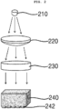
- FIG. 2 is a view showing a plurality of lenses in a handpiece 200 of a needle laser treatment system according to an embodiment of the present invention
- FIG. 3 is a view showing an optical lens unit 240 of a needle laser treatment system according to an embodiment of the present invention
- FIG. 4 is a view showing an optical lens unit 240 and a needle unit 300 of a needle laser treatment system according to an embodiment of the present invention
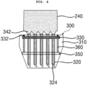
- FIG. 5 a view showing a needle unit 300 of a needle laser treatment system according to an embodiment of the present invention
- FIG. 6 is a block diagram showing a schematic configuration of a needle laser treatment system according to an embodiment of the present invention.
- a needle laser treatment system comprises: an optical cable 100 connected to a laser beam generator L to provide a laser beam generated by the laser beam generator L; a hand piece 200 having a plurality of lenses installed therein to amplify or extend the laser beam received from the optical cable 100; and a needle unit 300 connected to the bottom of the hand piece 200 to receive the laser beam through the hand piece 200, pass the laser beam through the skin surface, and directly irradiate the laser beam to an area of medical procedure in the skin, and the hand piece 200 comprises: a focus lens 210 through which the laser beam received from the optical cable 100 enters; a convex lens 220 for extending or amplifying the laser beam emitted from the focus lens 210; a collimate lens 230 for emitting the laser beam emitted from the convex lens 220 to be parallel to the traveling direction; and an optical lens unit 240 connected to the needle unit 300 and having a plurality of optical lenses installed therein to extend or amplify the laser beam emitted from
- the optical cable 100 is a component connected to the laser beam generator L to provide the laser beam generated by the laser beam generator L to the hand piece 200 and the needle unit 300, and may be configured to comprise an optical fiber therein.
- the optical cable 100 may comprise a cable electromotive force (EMF) to transfer high-frequency energy to the hand piece 200 and the needle unit 300.
- EMF cable electromotive force
- the handpiece 200 is a component having a plurality of lenses installed therein to amplify or extend the laser beam received from the optical cable 100, and may be made of a plastic material. In addition, glossy coating may be performed on the outer surface of the handpiece 200.
- the plurality of lenses installed inside the handpiece 200 comprises a focus lens 210, a convex lens 220, a collimate lens 230, and an optical lens unit 240, and the laser beam received from the optical cable 100 may passes through the lenses in order.
- the focus lens 210 is a component through which the laser beam received from the optical cable 100 enters, and is a component for diffusing and emitting the incident laser beam.
- the convex lens 220 is a component for extending or amplifying the laser beam emitted from the focus lens 210.
- the collimate lens 230 is a component for emitting the laser beam emitted from the convex lens 220 to be parallel to the traveling direction, and emitting the laser beam emitted to be parallel to the optical lens unit 240.
- the optical lens unit 240 is a component connected to the needle unit 300, and having a plurality of optical lenses installed therein to extend or amplify the laser beam emitted from the collimate lens 230 and transfer the laser beam to the needle unit 300.
- the optical lens unit 240 has a plurality of optical lenses inserted therein, and may be configured to comprise a convex portion 242 directly connected to the needle unit 300.
- the number of the convex portions 242 is the same as the number of the needle elements 320, and in an embodiment of the present invention, the number of the convex portions 242 and the needle elements 320 may be twentyfive.
- the present invention may improve the effect of laser treatment.
- connection unit 250 of a synthetic resin material for connecting the optical cable 100 may be configured on the top of the handpiece 200.
- a button unit 260 for controlling on/off of the hand piece 200 and the needle element 320 may be installed on one side of the outer surface of the hand piece 200 to start or stop the procedure of needle treatment.
- the needle unit 300 may comprise: a frame 310 formed hollow and made of a transparent material to be detachably installed on the bottom of the handpiece 200; a plurality of needle elements 320 arranged inside the frame 310 to emit the laser beam transferred through the plurality of optical lenses so that the laser beam may pass through the skin surface and be directly irradiated on an area of medical procedure in the skin; a circuit board unit 330 arranged on the inner upper side of the frame 310, electrically connected to the needle elements 320, and having the plurality of needle elements 320 installed therein; a control unit 340 electrically connected to the circuit board unit 330 to control the operation of the needle elements 320 and the circuit board unit 330; and a guide unit 350 installed to be spaced apart from the circuit board by a predetermined distance in the downward direction of the frame 310, and having a plurality of holes, through which the plurality of needle elements 320 may pass, formed to guide the vertical operation path of the needle elements 320
- the needle unit 300 may further comprise a guide bar 360 installed between the circuit board unit 330 and the guide unit 350 and having a spring installed therein to support the needle elements 320 to smoothly move up and down.
- the frame 310 is a component formed hollow, made of a transparent material, and detachably installed on the bottom of the handpiece 200, and may be made of a non-conductive synthetic resin material.
- the needle element 320 is a component arranged inside the frame 310 to emit the laser beam transferred through the plurality of optical lenses so that the laser beam may pass through the skin surface and be directly irradiated on an area of medical procedure in the skin, and may be provided in plurality.
- the needle element 320 may be configured to pass through the skin surface and directly penetrate into an area of medical procedure (dermis layer) in the skin to emit RF energy and laser energy in the skin.
- the depth of the needle element 320 inserted into the skin may be up to 3.5mm.
- the needle element 320 may be configured to emit the laser beam emitted through the needle element 320 at various wavelengths.
- the wavelength of the laser beam emitted through the needle element 320 may be 1450 to 1550nm for lifting improvement, acne treatment, scar treatment, or the like, and may be 530 to 590nm for treatment of pigmentation and redness of the skin and improvement of the functions of blood vessels.
- the needle element 320 is provided to have a diameter of 0.4mm, and has a needle hole 322 formed therein to have a diameter of 0.27mm, and the needle element 320 may be configured to pass through the skin surface and directly irradiate the laser beam to an area of medical procedure in the skin as a fiber optic bar 324 having a diameter of 0.25mm is inserted into the needle hole 322.
- the present invention may greatly improve the effect of medical procedure and treatment.
- the laser beam enters from the optical lenses, it is preferable to provide as many needle elements 320 as the number of the optical lenses and convex portions 242. In other words, it is preferable that as many needle elements 320 as the number of the optical lenses and convex portions 242 are provided.
- the circuit board unit 330 is a component arranged on the inner upper side of the frame 310, electrically connected to the needle elements 320, and having the plurality of needle elements 320 installed therein.
- the plurality of needle elements 320 may be installed in the circuit board unit 330 by soldering, and may be configured as a PCB substrate.
- the guide unit 350 is a component installed to be spaced apart from the circuit board by a predetermined distance in the downward direction of the frame 310, and having a plurality of holes, through which the plurality of needle elements 320 may pass, formed to guide the vertical operation path of the needle elements 320 and the circuit board unit 330. That is, in the present invention, the needle element 320 may smoothly move up and down along the hole formed in the guide unit 350. Accordingly, in the present invention, since the needle element 320 may move up and down along the guide of the guide unit 350 without being shaken left and right, the needle element 320 may be inserted into an accurate area of medical procedure, and thus enhance the effect of medical procedure.
- the guide bar 360 is a component installed between the circuit board unit 330 and the guide unit 350 and having a spring installed therein to support the needle elements 320 to smoothly move up and down. Accordingly, in the present invention, as the needle elements 320 may smoothly move up and down, the time of medical procedure can be reduced, and thus the medical procedure may be performed easily.
- substrate blocks 332 may be installed on both sides of the circuit board unit 330. It may be configured to couple one end of the substrate block 332 to the inner top of the frame 310 and connect the other end to the guide bar 360. Accordingly, in the present invention, the circuit board unit 330 may smoothly move up and down, together with the needle elements 320, by the guide bar 360.
- the control unit 340 a component electrically connected to the circuit board unit 330 to control the operation of the needle elements 320 and the circuit board unit 330. That is, the control unit 340 is configured to control the up and down operation state of the needle elements 320 so that the needle elements 320 may be inserted into the skin.
- the needle laser treatment system may further comprise an input device 400 configured to input the depth of the needle element 320 inserted into the skin as a numerical value according to implementation.
- control unit 340 may be configured to comprise: a receiving unit 342 for receiving the numerical value input into the input device 400; a measurement unit 344 for measuring the depth of the needle element 320 actually inserted into the skin; and an automatic adjustment unit 346 for controlling the operation of the needle element 320 to automatically adjust the degree of the needle element 320 inserted into the skin by comparing the numerical value received through the receiving unit 342 and the measurement value measured through the measurement unit 344.
- the present invention may further enhance the accuracy and effect of the medical procedure.
- the present invention may further comprise a display device 500 for displaying the depth of the needle element 320 inserted into the skin in order to adjust the depth inserted into the skin when the needle element 320 is inserted into the skin under the control of the controller 340.
- the display device 500 may be configured to display the numerical value input through the input device 400, the measurement value measured through the measurement unit 344, and the value of the length of the inserted needle element 320 adjusted through the automatic adjustment unit 346. Therefore, an operator may easily know various values through the display device 500, and perform medical procedures more efficiently.
- L Laser beam generator 100: Optical cable 200: Hand piece 210: Focus lens 220: Convex lens 230: Collimate lens 240: Optical lens unit 242: Convex portion 250: Connection unit 260: Button unit 300: Needle unit 310: Frame 320: Needle element 322: Needle hole 324: Fiber optic bar 330: Circuit board unit 332: Substrate block 340: Control unit 342: Receiving unit 344: Measurement unit 346: Automatic adjustment unit 350: Guide unit 360: Guide bar 400: Input device 500: Display device
Landscapes
- Health & Medical Sciences (AREA)
- Engineering & Computer Science (AREA)
- Biomedical Technology (AREA)
- Life Sciences & Earth Sciences (AREA)
- General Health & Medical Sciences (AREA)
- Veterinary Medicine (AREA)
- Nuclear Medicine, Radiotherapy & Molecular Imaging (AREA)
- Public Health (AREA)
- Animal Behavior & Ethology (AREA)
- Physics & Mathematics (AREA)
- Pathology (AREA)
- Radiology & Medical Imaging (AREA)
- Optics & Photonics (AREA)
- Surgery (AREA)
- Biophysics (AREA)
- Electromagnetism (AREA)
- Otolaryngology (AREA)
- Heart & Thoracic Surgery (AREA)
- Medical Informatics (AREA)
- Molecular Biology (AREA)
- Pain & Pain Management (AREA)
- Radiation-Therapy Devices (AREA)
- Laser Surgery Devices (AREA)
Claims (5)
- Système de traitement laser à aiguille, comprenant :un câble optique connecté à un générateur de faisceau laser pour fournir un faisceau laser généré par le générateur de faisceau laser ;une pièce à main comportant une pluralité de lentilles qui y sont installées pour amplifier ou étendre le faisceau laser reçu du câble optique ; etune unité d'aiguille connectée à une partie inférieure de la pièce à main pour recevoir le faisceau laser à travers la pièce à main, pour faire passer le faisceau laser à travers la surface de la peau, et pour irradier directement le faisceau laser sur une zone de procédure médicale dans la peau, dans lequella pièce à main comprend :une lentille de focalisation à travers laquelle entre le faisceau laser reçu du câble optique ;une lentille convexe pour étendre ou amplifier le faisceau laser émis par la lentille de focalisation ;une lentille de collimation pour émettre le faisceau laser émis par la lentille convexe de manière à ce qu'il soit parallèle à une direction de déplacement ; etune unité à lentilles optiques connectée à l'unité d'aiguille et comportant une pluralité de lentilles optiques qui y sont installées pour étendre ou amplifier le faisceau laser émis par la lentille de collimation et transférer le faisceau laser à l'unité d'aiguille.
- Système selon la revendication 1, dans lequel l'unité d'aiguille comprend :une monture creuse et constitué d'un matériau transparent à installer de manière détachable sur le fond de la pièce à main ;une pluralité d'éléments d'aiguille agencés à l'intérieur de la monture pour émettre le faisceau laser transféré à travers la pluralité de lentilles optiques de sorte que le faisceau laser puisse traverser la surface de la peau et être directement irradié sur une zone de procédure médicale dans la peau ;une unité de circuit imprimé agencée sur un côté supérieur interne de la monture, connectée électriquement aux éléments d'aiguille, et dans laquelle la pluralité d'éléments d'aiguille est installée ;une unité de contrôle connectée électriquement à l'unité de circuit imprimé pour contrôler le fonctionnement des éléments d'aiguille et de l'unité de circuit imprimé ; etune unité de guidage installée pour être espacée du circuit imprimé d'une distance prédéterminée dans une direction vers le bas de la monture, et comportant une pluralité de trous, à travers lesquels la pluralité d'éléments d'aiguille peuvent passer, formés pour guider un chemin d'actionnement vertical des éléments d'aiguille et de l'unité de circuit imprimé.
- Système selon la revendication 2, dans lequel l'unité d'aiguille comprend en outre une barre de guidage installée entre l'unité de circuit imprimé et l'unité de guidage et comportant un ressort qui y est installé pour supporter les éléments d'aiguille afin qu'ils se déplacent en douceur vers le haut et vers le bas.
- Système selon la revendication 3, dans lequel l'élément d'aiguille est pourvu pour avoir un diamètre de 0,4 mm, et comporte un trou d'aiguille qui y est formé pour avoir un diamètre de 0,27 mm, et l'élément d'aiguille est configuré pour traverser la surface de la peau et irradier directement le faisceau laser sur la zone de procédure médicale dans la peau quand une barre de fibre optique ayant un diamètre de 0,25 mm est insérée dans le trou d'aiguille.
- Système selon la revendication 2, dans lequel autant d'éléments d'aiguille sont configurés que le nombre de lentilles optiques de l'unité à lentilles optiques.
Applications Claiming Priority (2)
| Application Number | Priority Date | Filing Date | Title |
|---|---|---|---|
| KR1020200095563A KR102151923B1 (ko) | 2020-07-30 | 2020-07-30 | 니들 레이저 치료 시스템 |
| PCT/KR2021/003266 WO2022025383A1 (fr) | 2020-07-30 | 2021-03-16 | Système de traitement par aiguille laser |
Publications (4)
| Publication Number | Publication Date |
|---|---|
| EP4190262A1 EP4190262A1 (fr) | 2023-06-07 |
| EP4190262A4 EP4190262A4 (fr) | 2024-08-21 |
| EP4190262C0 EP4190262C0 (fr) | 2025-05-14 |
| EP4190262B1 true EP4190262B1 (fr) | 2025-05-14 |
Family
ID=72450114
Family Applications (1)
| Application Number | Title | Priority Date | Filing Date |
|---|---|---|---|
| EP21849459.9A Active EP4190262B1 (fr) | 2020-07-30 | 2021-03-16 | Système de traitement par aiguille laser |
Country Status (6)
| Country | Link |
|---|---|
| US (1) | US12151122B1 (fr) |
| EP (1) | EP4190262B1 (fr) |
| JP (1) | JP7511293B2 (fr) |
| KR (1) | KR102151923B1 (fr) |
| CN (1) | CN115955991A (fr) |
| WO (1) | WO2022025383A1 (fr) |
Families Citing this family (5)
| Publication number | Priority date | Publication date | Assignee | Title |
|---|---|---|---|---|
| KR102151923B1 (ko) * | 2020-07-30 | 2020-09-03 | 박인규 | 니들 레이저 치료 시스템 |
| WO2024011075A2 (fr) * | 2022-07-05 | 2024-01-11 | StimuSIL, Inc. | Dispositif de distribution de lumière dermique pour luminothérapie |
| KR20240134593A (ko) | 2023-03-02 | 2024-09-10 | 박원희 | 니들 유닛을 구비하는 치료장치 |
| KR102609570B1 (ko) | 2023-05-11 | 2023-12-01 | 박원희 | 니들군을 구비하는 피부시술장치 및 그 구동방법 |
| KR102938546B1 (ko) | 2025-08-11 | 2026-03-13 | 주식회사 엔스킨 | 니들 색점을 이용한 피부용 레이저 장치 |
Family Cites Families (19)
| Publication number | Priority date | Publication date | Assignee | Title |
|---|---|---|---|---|
| GB2184021A (en) | 1985-12-13 | 1987-06-17 | Micra Ltd | Laser treatment apparatus for port wine stains |
| US6355054B1 (en) * | 1999-11-05 | 2002-03-12 | Ceramoptec Industries, Inc. | Laser system for improved transbarrier therapeutic radiation delivery |
| US20070005119A1 (en) * | 2005-06-30 | 2007-01-04 | Crohn Steven S | Apparatus and method for the point treatment of a patient by acupuncture and light |
| KR100820164B1 (ko) * | 2007-03-31 | 2008-04-08 | 한국전기연구원 | 피부질환 치료용 레이저 장치 |
| KR101010957B1 (ko) | 2008-07-18 | 2011-01-26 | 연세대학교 산학협력단 | 다채널 레이저 침 시스템 |
| KR100914142B1 (ko) * | 2009-01-16 | 2009-08-28 | 주식회사 루트로닉 | 의료용 레이저수술기의 광화이버 어셈블리 |
| KR20100101420A (ko) * | 2009-03-09 | 2010-09-17 | 전민용 | 마이크로니들 및 진동발생장치와 연동된 치료 및 스킨케어 기기 |
| KR101088490B1 (ko) | 2009-06-29 | 2011-11-30 | 광주과학기술원 | 광섬유에 금속을 전기 도금한 침습형 침 및 그 제조 방법 |
| KR100963395B1 (ko) * | 2009-12-16 | 2010-06-14 | 단국대학교 산학협력단 | 적외선 오피오레이저를 이용한 지방제거 방법 및 장치 |
| US20120010513A1 (en) * | 2010-07-08 | 2012-01-12 | Wong Stephen T C | Chemically-selective, label free, microendoscopic system based on coherent anti-stokes raman scattering and microelectromechanical fiber optic probe |
| DE102011052002B4 (de) * | 2011-07-20 | 2013-04-11 | Telesto GmbH | Lasertherapiesystem mit UVA- und IR-Laser-Licht zur gerichteten Erzeugung einer dermalen Kollagen-Matrix |
| KR101487737B1 (ko) * | 2012-03-21 | 2015-01-29 | 연세대학교 원주산학협력단 | 체내 직접 조사 가능한 레이저 침 시스템 |
| EP3498211B1 (fr) | 2013-08-09 | 2024-12-25 | The General Hospital Corporation | Appareil de traitement du mélasme dermique |
| KR101531646B1 (ko) | 2013-08-29 | 2015-06-25 | 한국전기연구원 | 광섬유로 이루어진 광출력부를 가지는 의료용 핸드피스 |
| DE102014017197B4 (de) * | 2014-11-21 | 2016-06-09 | Markus Depfenhart | Therapiesystem zur gerichteten transkutanen Rekonstruktion des Hautskeletts |
| US10765851B2 (en) * | 2015-03-03 | 2020-09-08 | Guided Therapy Systems Llc | Methods and systems for material transport across an impermeable or semi-permeable membrane via artificially created microchannels |
| KR101924492B1 (ko) | 2017-06-26 | 2018-12-03 | 고려대학교 산학협력단 | 의료용 광조사 및 모니터링 장치 |
| KR102125770B1 (ko) * | 2018-05-31 | 2020-06-23 | 주식회사 큐리오시스 | 마이크로니들 플레이트의 부스터 |
| KR102151923B1 (ko) | 2020-07-30 | 2020-09-03 | 박인규 | 니들 레이저 치료 시스템 |
-
2020
- 2020-07-30 KR KR1020200095563A patent/KR102151923B1/ko active Active
-
2021
- 2021-03-16 WO PCT/KR2021/003266 patent/WO2022025383A1/fr not_active Ceased
- 2021-03-16 US US18/018,726 patent/US12151122B1/en active Active
- 2021-03-16 EP EP21849459.9A patent/EP4190262B1/fr active Active
- 2021-03-16 JP JP2023507288A patent/JP7511293B2/ja active Active
- 2021-03-16 CN CN202180050142.7A patent/CN115955991A/zh active Pending
Also Published As
| Publication number | Publication date |
|---|---|
| US12151122B1 (en) | 2024-11-26 |
| EP4190262A4 (fr) | 2024-08-21 |
| EP4190262C0 (fr) | 2025-05-14 |
| KR102151923B1 (ko) | 2020-09-03 |
| WO2022025383A1 (fr) | 2022-02-03 |
| JP2023535991A (ja) | 2023-08-22 |
| CN115955991A (zh) | 2023-04-11 |
| EP4190262A1 (fr) | 2023-06-07 |
| JP7511293B2 (ja) | 2024-07-05 |
Similar Documents
| Publication | Publication Date | Title |
|---|---|---|
| EP4190262B1 (fr) | Système de traitement par aiguille laser | |
| US20100004645A1 (en) | Invasive dual-wavelength laser acupuncture | |
| CN105342700B (zh) | 用于光学组织表面治疗的独立机头和方法 | |
| US7736382B2 (en) | Apparatus for optical stimulation of nerves and other animal tissue | |
| EP4192337B1 (fr) | Planification d'ablation de tumeur par cartographie optique interstitielle | |
| JP6509829B2 (ja) | 皮膚特性のための測定装置、及び、非侵襲的処理装置 | |
| US20130123648A1 (en) | Medical diagnosis and treatment using multi-core optical fibers | |
| CN109688964A (zh) | 用于毛发去除的自动化系统和方法 | |
| US12232807B2 (en) | Methods, devices, and support structures for assembling optical fibers in catheter tips | |
| US12011218B2 (en) | Methods, devices, and support structures for assembling optical fibers in catheter tips | |
| KR102276076B1 (ko) | 레이저 치료기 | |
| KR20160101736A (ko) | 관절염 치료를 위한 최소 침습적 레이저 침 시스템 | |
| KR101652941B1 (ko) | 레이저 침 및 레이저 침 시스템 | |
| JP2021527516A (ja) | 組織治療のための光学アレイ | |
| EP4090228B1 (fr) | Procédés, dispositifs et structures de support pour assembler des fibres optiques dans des pointes de cathéter | |
| US12023511B2 (en) | RF therapeutic device and method for controlling same | |
| CN106039593A (zh) | 基于组织血氧检测的激光照射系统 | |
| US10194987B2 (en) | Laser irradiation apparatus and laser irradiation method | |
| JP2018099162A (ja) | 光治療装置 | |
| KR100457964B1 (ko) | 레이저빔 조사장치 | |
| US20210007803A1 (en) | Laser drilling of pia mater | |
| KR20240114264A (ko) | 가변 펄스 레이저 빔을 치료하려는 부위에 조사하여 치료를 수행하는 레이저 수술 장치 | |
| KR20030081668A (ko) | 레이저광을 이용한 치료장치 및 그 치료방법 | |
| KR101652938B1 (ko) | 레이저 침 및 레이저 침 시스템 | |
| KR20260064088A (ko) | 침습형 레이저침 치료 장치 및 이의 출력 파워 조정 방법 |
Legal Events
| Date | Code | Title | Description |
|---|---|---|---|
| STAA | Information on the status of an ep patent application or granted ep patent |
Free format text: STATUS: THE INTERNATIONAL PUBLICATION HAS BEEN MADE |
|
| PUAI | Public reference made under article 153(3) epc to a published international application that has entered the european phase |
Free format text: ORIGINAL CODE: 0009012 |
|
| STAA | Information on the status of an ep patent application or granted ep patent |
Free format text: STATUS: REQUEST FOR EXAMINATION WAS MADE |
|
| 17P | Request for examination filed |
Effective date: 20230223 |
|
| AK | Designated contracting states |
Kind code of ref document: A1 Designated state(s): AL AT BE BG CH CY CZ DE DK EE ES FI FR GB GR HR HU IE IS IT LI LT LU LV MC MK MT NL NO PL PT RO RS SE SI SK SM TR |
|
| DAV | Request for validation of the european patent (deleted) | ||
| DAX | Request for extension of the european patent (deleted) | ||
| A4 | Supplementary search report drawn up and despatched |
Effective date: 20240724 |
|
| RIC1 | Information provided on ipc code assigned before grant |
Ipc: A61N 5/067 20060101ALI20240718BHEP Ipc: A61B 18/00 20060101ALI20240718BHEP Ipc: A61N 5/06 20060101ALI20240718BHEP Ipc: A61B 18/20 20060101AFI20240718BHEP |
|
| GRAP | Despatch of communication of intention to grant a patent |
Free format text: ORIGINAL CODE: EPIDOSNIGR1 |
|
| STAA | Information on the status of an ep patent application or granted ep patent |
Free format text: STATUS: GRANT OF PATENT IS INTENDED |
|
| INTG | Intention to grant announced |
Effective date: 20250227 |
|
| GRAS | Grant fee paid |
Free format text: ORIGINAL CODE: EPIDOSNIGR3 |
|
| GRAA | (expected) grant |
Free format text: ORIGINAL CODE: 0009210 |
|
| STAA | Information on the status of an ep patent application or granted ep patent |
Free format text: STATUS: THE PATENT HAS BEEN GRANTED |
|
| AK | Designated contracting states |
Kind code of ref document: B1 Designated state(s): AL AT BE BG CH CY CZ DE DK EE ES FI FR GB GR HR HU IE IS IT LI LT LU LV MC MK MT NL NO PL PT RO RS SE SI SK SM TR |
|
| REG | Reference to a national code |
Ref country code: GB Ref legal event code: FG4D |
|
| REG | Reference to a national code |
Ref country code: CH Ref legal event code: EP |
|
| REG | Reference to a national code |
Ref country code: IE Ref legal event code: FG4D |
|
| U01 | Request for unitary effect filed |
Effective date: 20250514 |
|
| U07 | Unitary effect registered |
Designated state(s): AT BE BG DE DK EE FI FR IT LT LU LV MT NL PT RO SE SI Effective date: 20250520 |
|
| PG25 | Lapsed in a contracting state [announced via postgrant information from national office to epo] |
Ref country code: ES Free format text: LAPSE BECAUSE OF FAILURE TO SUBMIT A TRANSLATION OF THE DESCRIPTION OR TO PAY THE FEE WITHIN THE PRESCRIBED TIME-LIMIT Effective date: 20250514 |
|
| PG25 | Lapsed in a contracting state [announced via postgrant information from national office to epo] |
Ref country code: GR Free format text: LAPSE BECAUSE OF FAILURE TO SUBMIT A TRANSLATION OF THE DESCRIPTION OR TO PAY THE FEE WITHIN THE PRESCRIBED TIME-LIMIT Effective date: 20250815 Ref country code: NO Free format text: LAPSE BECAUSE OF FAILURE TO SUBMIT A TRANSLATION OF THE DESCRIPTION OR TO PAY THE FEE WITHIN THE PRESCRIBED TIME-LIMIT Effective date: 20250814 |
|
| PG25 | Lapsed in a contracting state [announced via postgrant information from national office to epo] |
Ref country code: PL Free format text: LAPSE BECAUSE OF FAILURE TO SUBMIT A TRANSLATION OF THE DESCRIPTION OR TO PAY THE FEE WITHIN THE PRESCRIBED TIME-LIMIT Effective date: 20250514 |
|
| PG25 | Lapsed in a contracting state [announced via postgrant information from national office to epo] |
Ref country code: HR Free format text: LAPSE BECAUSE OF FAILURE TO SUBMIT A TRANSLATION OF THE DESCRIPTION OR TO PAY THE FEE WITHIN THE PRESCRIBED TIME-LIMIT Effective date: 20250514 |
|
| PG25 | Lapsed in a contracting state [announced via postgrant information from national office to epo] |
Ref country code: RS Free format text: LAPSE BECAUSE OF FAILURE TO SUBMIT A TRANSLATION OF THE DESCRIPTION OR TO PAY THE FEE WITHIN THE PRESCRIBED TIME-LIMIT Effective date: 20250814 |
|
| PG25 | Lapsed in a contracting state [announced via postgrant information from national office to epo] |
Ref country code: IS Free format text: LAPSE BECAUSE OF FAILURE TO SUBMIT A TRANSLATION OF THE DESCRIPTION OR TO PAY THE FEE WITHIN THE PRESCRIBED TIME-LIMIT Effective date: 20250914 |
|
| PG25 | Lapsed in a contracting state [announced via postgrant information from national office to epo] |
Ref country code: SM Free format text: LAPSE BECAUSE OF FAILURE TO SUBMIT A TRANSLATION OF THE DESCRIPTION OR TO PAY THE FEE WITHIN THE PRESCRIBED TIME-LIMIT Effective date: 20250514 |
|
| PG25 | Lapsed in a contracting state [announced via postgrant information from national office to epo] |
Ref country code: CZ Free format text: LAPSE BECAUSE OF FAILURE TO SUBMIT A TRANSLATION OF THE DESCRIPTION OR TO PAY THE FEE WITHIN THE PRESCRIBED TIME-LIMIT Effective date: 20250514 |
|
| PG25 | Lapsed in a contracting state [announced via postgrant information from national office to epo] |
Ref country code: SK Free format text: LAPSE BECAUSE OF FAILURE TO SUBMIT A TRANSLATION OF THE DESCRIPTION OR TO PAY THE FEE WITHIN THE PRESCRIBED TIME-LIMIT Effective date: 20250514 |
|
| PLBE | No opposition filed within time limit |
Free format text: ORIGINAL CODE: 0009261 |
|
| STAA | Information on the status of an ep patent application or granted ep patent |
Free format text: STATUS: NO OPPOSITION FILED WITHIN TIME LIMIT |
|
| REG | Reference to a national code |
Ref country code: CH Ref legal event code: L10 Free format text: ST27 STATUS EVENT CODE: U-0-0-L10-L00 (AS PROVIDED BY THE NATIONAL OFFICE) Effective date: 20260325 |
|
| U20 | Renewal fee for the european patent with unitary effect paid |
Year of fee payment: 6 Effective date: 20260226 |
|
| 26N | No opposition filed |
Effective date: 20260217 |