EP4190267A1 - Manipulateur pour travail microscopique - Google Patents
Manipulateur pour travail microscopique Download PDFInfo
- Publication number
- EP4190267A1 EP4190267A1 EP20947001.2A EP20947001A EP4190267A1 EP 4190267 A1 EP4190267 A1 EP 4190267A1 EP 20947001 A EP20947001 A EP 20947001A EP 4190267 A1 EP4190267 A1 EP 4190267A1
- Authority
- EP
- European Patent Office
- Prior art keywords
- end effector
- manipulator
- work
- microscopic
- microscopic work
- Prior art date
- Legal status (The legal status is an assumption and is not a legal conclusion. Google has not performed a legal analysis and makes no representation as to the accuracy of the status listed.)
- Granted
Links
Images


Classifications
-
- A—HUMAN NECESSITIES
- A61—MEDICAL OR VETERINARY SCIENCE; HYGIENE
- A61B—DIAGNOSIS; SURGERY; IDENTIFICATION
- A61B34/00—Computer-aided surgery; Manipulators or robots specially adapted for use in surgery
- A61B34/70—Manipulators specially adapted for use in surgery
- A61B34/72—Micromanipulators
-
- A—HUMAN NECESSITIES
- A61—MEDICAL OR VETERINARY SCIENCE; HYGIENE
- A61B—DIAGNOSIS; SURGERY; IDENTIFICATION
- A61B34/00—Computer-aided surgery; Manipulators or robots specially adapted for use in surgery
- A61B34/30—Surgical robots
-
- B—PERFORMING OPERATIONS; TRANSPORTING
- B25—HAND TOOLS; PORTABLE POWER-DRIVEN TOOLS; MANIPULATORS
- B25J—MANIPULATORS; CHAMBERS PROVIDED WITH MANIPULATION DEVICES
- B25J17/00—Joints
- B25J17/02—Wrist joints
- B25J17/0258—Two-dimensional joints
- B25J17/0266—Two-dimensional joints comprising more than two actuating or connecting rods
-
- B—PERFORMING OPERATIONS; TRANSPORTING
- B25—HAND TOOLS; PORTABLE POWER-DRIVEN TOOLS; MANIPULATORS
- B25J—MANIPULATORS; CHAMBERS PROVIDED WITH MANIPULATION DEVICES
- B25J7/00—Micromanipulators
-
- B—PERFORMING OPERATIONS; TRANSPORTING
- B25—HAND TOOLS; PORTABLE POWER-DRIVEN TOOLS; MANIPULATORS
- B25J—MANIPULATORS; CHAMBERS PROVIDED WITH MANIPULATION DEVICES
- B25J9/00—Program-controlled manipulators
- B25J9/003—Program-controlled manipulators having parallel kinematics
- B25J9/0033—Program-controlled manipulators having parallel kinematics with kinematics chains having a prismatic joint at the base
- B25J9/0042—Program-controlled manipulators having parallel kinematics with kinematics chains having a prismatic joint at the base with kinematics chains of the type prismatic-universal-universal
-
- B—PERFORMING OPERATIONS; TRANSPORTING
- B25—HAND TOOLS; PORTABLE POWER-DRIVEN TOOLS; MANIPULATORS
- B25J—MANIPULATORS; CHAMBERS PROVIDED WITH MANIPULATION DEVICES
- B25J9/00—Program-controlled manipulators
- B25J9/10—Program-controlled manipulators characterised by positioning means for manipulator elements
- B25J9/14—Program-controlled manipulators characterised by positioning means for manipulator elements fluid
- B25J9/146—Rotary actuators
-
- G—PHYSICS
- G02—OPTICS
- G02B—OPTICAL ELEMENTS, SYSTEMS OR APPARATUS
- G02B21/00—Microscopes
- G02B21/32—Micromanipulators structurally combined with microscopes
Definitions
- the present invention relates to a manipulator for microscopic work.
- a master-slave manipulator is capable of reproducing human motions and also performing operations of scaled-down human motions and, if operations related to surgery are performed by the manipulator that operates accurately, it is possible to reduce the burden on the surgeon while eliminating the influence of shaky hands or the like to secure accuracy, and efficiency of the surgery is expected to be improved.
- the present inventors have proposed a microscopic work assistance system capable of performing work assistance efficiently by properly performing operations related to work by remote control and reducing a burden on an operator, and a manipulator for microscopic work that is used in the microscopic work assistance system (see PTL 1).
- the present invention has been made in view of the above problem, and an object thereof is to provide a manipulator for microscopic work capable of controlling the rotational operation of an end effector smoothly and reliably.
- a manipulator for microscopic work is a manipulator for microscopic work that executes a predetermined operation related to microscopic work on a work object instead of a person.
- the manipulator for microscopic work includes: a parallel link mechanism with three or more degrees of freedom, the parallel link mechanism includes: a base that is supported on a predetermined part in a space in which the work object is present; an end effector that is configured to handle the work object or an instrument for work; and a plurality of links that are disposed in parallel between the base and the end effector, the parallel link mechanism configured to be capable of changing a position and an orientation of the end effector with respect to the base in a predetermined range.
- the parallel link mechanism configured so that a plurality of linear actuators supported on the base are used to linearly shift one end part of each of the plurality of links so as to move the end effector coupled to another end part of each link.
- the parallel link mechanism further includes a rotation support part that is provided between the end effector and the parallel link mechanism and is configured to support the end effector rotatably around a predetermined rotational axis and a hydraulic drive mechanism that is configured to generate rotating power around the rotational axis to the end effector.
- the parallel link mechanism is configured to impart, from the exterior to the hydraulic drive mechanism, change in working-fluid hydraulic pressure so as to generate movement for rotating the end effector.
- the manipulator for microscopic work capable of controlling the rotational operation of the end effector smoothly and reliably.
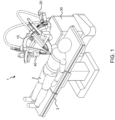
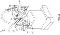
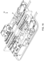
- a device for microscopic work 1 includes a manipulator for microscopic work 10 according to the present embodiment, a robot part 20 in which the manipulator for microscopic work 10 is mounted to a tip part, a base 30 that supports the robot part 20 from below, an imaging part 40 that is mounted to the base 30 similarly and captures an image of a surgery object, and a control part that is not shown and controls operations of the entire device for microscopic work 1.
- a display part is provided on an as needed basis.
- the robot part 20 has three degrees of freedom of rotation and one degree of freedom of translation in a radial direction.
- a pair of the robot part 20 and the manipulator for microscopic work 10 are provided on the base 30, but the number of robot parts 20 and the number of manipulators for microscopic work 10 are not particularly limited.
- the imaging part 40 captures images of a tip operation part of an end effector of the manipulator for microscopic work 10 described later, and a surgery object, and is disposed at a position above, e.g., the robot part 20 that allows the imaging part 40 to overlook at least a tip of the manipulator for microscopic work 10 and the surgery object.
- This imaging part 40 is a known video camera capable of acquiring a captured image having high resolution that can secure reproducibility even when the captured image is enlarged with the same magnification as that of a conventional microscope for microsurgery and, therefore, the detailed description thereof will be omitted.
- the display part displays the image of the surgery object acquired by the imaging part 40 to a user such that the user can visually recognize the surgery object while enlarging the image of the surgery object on an as needed basis.
- This display part is a known display device such as a liquid crystal display capable of displaying the image obtained by imaging with high resolution and, therefore, the detailed description thereof will be omitted.
- the base 30 includes a movement mechanism that is not shown, and is configured to be movable to a predetermined position based on movement support from the control part on a floor of an operating room that is not shown together with the manipulator for microscopic work 10, the robot part 20, and the imaging part 40 provided on the base 30.
- the device for microscopic work 1 of the present embodiment is allowed to move close to or away from a surgical table 3 on which a patient 2 serving as the surgery object shown in Fig. 1 lies and, further, it is possible to dispose at least the tip part of the manipulator for microscopic work 10 at a surgery part of the patient 2.
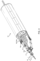
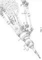
- the manipulator for microscopic work 10 includes a base that is not shown and is supported by the robot part 20, an end effector 12 that handles the surgery object or a surgical instrument, six links 13 that are disposed in parallel, a rotation support part 17 that is disposed between the base and the end effector 12, and six linear actuators 14 that are supported on the base and shift the individual links 13.
- the base, the end effector 12, the links 13, and the linear actuators 14 constitute a parallel link mechanism with six degrees of freedom in which the linear actuators 14 are used to linearly shift one end part of each of the links 13 so as to move the end effector 12 coupled to the other end part of the links 13.
- the parallel link mechanism is capable of changing the position and the orientation of the end effector 12 that handles the surgery object or the surgical instrument with respect to the base in a predetermined range and, the parallel link mechanism has six degrees of freedom, and hence the parallel link mechanism can give movement equal to movement in the case where the end effector 12 is supported by a hand to the end effector 12 at the tip.
- the linear actuator 14 is a moving-coil linear motor in which a coil 15b constitutes a part of a mover 15 and a permanent magnet 16a constitutes a part of a stator 16.
- the mover 15 includes a linear-motion slider 15a that is provided so as to be able to move linearly with respect to the base, a thin cylindrically disposed coil 15b that is integrally mounted to the linear-motion slider 15a such that its moving direction is parallel to the linear-motion slider 15a, and a coupling member 15c that is mounted to a tip of the coil 15b and couples the coil 15b and the linear-motion slider 15a.
- One end part of the link 13 is coupled and fixed to a tip of the linear-motion slider 15a in the mover 15 via the coupling member 15c, and it follows that the one end part of the link 13 linearly moves together with the mover 15 including the linear-motion slider 15a.
- the stator 16 includes a permanent magnet 16a that is formed into a cylindrical shape that is thicker and shorter than the coil 15b of the mover 15, and is fixed to the base by fixing means that is not shown.
- the cylindrical permanent magnet 16a fixed to the base is aligned with the coil 15b of the mover 15 in a cylinder axis direction, and the coil 15b is disposed so as to movably penetrate a cylinder inner space part of the permanent magnet 16b.
- linear motor as the linear actuator 14, as compared with other linear-motion mechanisms such as a ball screw and the like, it is possible to reduce a mechanical movable part and also reduce a contact part involving sliding or rolling, and it is possible to increase reliability as the mechanism and suppress power consumption required for drive by reducing frictional resistance without causing backlash.
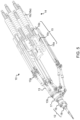
- the linear actuators 14 that are linear motors constituted by the movers 15 and the stators 16 are parallel to each other in the moving direction of each mover 15, and are arranged to be disposed around a predetermined virtual center line that is parallel to the moving direction of the mover 15 and extends in a longitudinal direction of each linear actuator 14 such that the permanent magnet 16a of each stator 16 and the coil 15b of each mover 15 are closest to the virtual center line, and the individual permanent magnets 16a are disposed at regular intervals and the individual coils 15b are disposed at regular intervals around the virtual center line.
- the permanent magnet 16a constituting the stator 16 is disposed so as to penetrate the cylinder inner space part to be close to the other coils 15b other than the coils 15b constituting a pair of the linear motors, unlike the coil 15b, the fixed permanent magnet 16a does not have fluctuation of a magnetic field, and hence the permanent magnet 16a does not exert a magnetic influence on the movement of each of the other coils 15b.
- the movers 15 and the stators 16 of the individual linear motors constituting the linear actuators 14 are disposed to be arranged around the virtual center line, and hence the linear actuator parts of the manipulator for microscopic work 10 can be integrated into a compact structure. Further, the end part of the coil 15b of the mover 15 that fluctuates a fixed magnetic field does not approach the permanent magnet 16a of the stator 16 significantly due to a mechanical structure, and hence it is possible to suppress the fluctuation of the magnetic field that causes cogging against the movement of the mover 15, and it is possible to implement the smooth operation of the linear actuator 14.
- the link 13 is configured such that joints 13a and 13b each having a plurality of degrees of freedom for being coupled to the linear actuator 14 and the rotation support part 17 are provided at both ends of a bar-shaped body in which substantially bar-shaped two members that have high rigidity and don't deform are coupled and combined with each other in a longitudinal direction.
- This link 13 has a structure in which the substantially bar-shaped members that constitute the bar-shaped body are rotatably coupled to each other and a certain degree of freedom of rotation about an axis parallel to a mutual longitudinal direction is provided between a part of the link 13 close to one end and a part of the link 13 close to the other end.
- the joint 13a at one end part of the link 13 has a structure having a certain degree of freedom of each of rotations about two axes that are orthogonal to each other, and is coupled to the end part of the linear-motion slider 15a of the linear actuator 14.
- the joint 13b at the other end part of the link 13 has a structure having a certain degree of freedom of each of rotations about two axes that are orthogonal to each other similarly to the above description, and is coupled to the rotation support part 17.
- each link 13 can freely change the orientation with respect to the linear actuator 14 and the rotation support part 17 coupled to the link 13 similarly to the case where coupling is performed by using a ball joint.
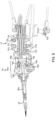
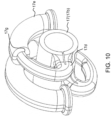
- the rotation support part 17 includes an outer tubular member 17a that is formed into an outer diameter tubular shape, and an inner tubular member 17b that is accommodated in a hollow part of the outer tubular member 17a similarly. Inside the outer tubular member 17a, a doughnut-shaped hollow part 17c is formed around the center axis of the outer tubular member 17a.
- the inner tubular member 17b is provided with an arc-shaped guide member 17d that protrudes from the inner tubular member 17b and extends around the center axis of the inner tubular member 17b (this center axis matches the center axis of the outer tubular member 17a).
- a rolling diaphragm 17e made of a stretchable material such as, e.g., silicone rubber is provided.
- the rolling diaphragm 17e includes a diaphragm main body 17f that is formed into an arc shape having substantially the same center as that of the guide member 17d, and an arc-shaped concave part 17g that is formed on the side of one end of the diaphragm main body 17f (on the side of a right end in Fig. 15 ) and is formed to be slightly larger in diameter than the outer periphery of the guide member 17d.
- the guide member 17d of the inner tubular member 17b is fitted in the concave part 17g of the rolling diaphragm 17e.
- a concave part that is not shown is also formed on a side opposite to the temporary side on which the concave part 17g is provided, and a working fluid is supplied to this concave part from a hydraulic pressure supply mechanism described later. That is, the concave part in the diaphragm main body 17f functions as a working fluid chamber.
- Fig. 11 shows a state in which the inside of the diaphragm main body 17f of the rolling diaphragm 17e is filled with the working fluid and, as a result, the guide member 17d is rotated counterclockwise in the drawing.
- Fig. 12 shows a state in which the working fluid is discharged from the inside of the diaphragm main body 17f of the rolling diaphragm 17e and, as a result, the guide member 17d is rotated counterclockwise in the drawing.
- the outer tubular member 17a and the inner tubular member 17b are fixed so as to be rotatable relative to each other by a bearing 17h.
- the outer tubular member 17a is fixed to the joint 13b of the link 13. Consequently, the inner tubular member 17b is rotated relative to the outer tubular member 17a in response to an increase or a decrease in hydraulic pressure by working fluid supply.
- This inner tubular member 17b is coupled to the end effector 12, and hence, as a result, the end effector 12 is also rotated in response to an increase or a decrease in hydraulic pressure by the working fluid supply.
- the inner tubular member 17b and the rolling diaphragm 17e of the rotation support part 17 correspond to a hydraulic drive mechanism that generates rotating power around the center axis of the inner tubular member 17b in the end effector 12.
- the end effector 12 can execute handling of the surgery object or the surgical instrument.
- this end effector 12 includes a tip operation part 18 that executes the handling of the surgery object or the surgical instrument with movement of opening and closing with one degree of freedom that is separate from overall movement by the parallel link mechanism, and a hydraulic drive mechanism 19 that generates the movement of handling the surgery object or the surgical instrument of this tip operation part 18.
- the tip operation part 18 is detachably attached to the hydraulic drive mechanism 19, and can be separated from the hydraulic drive mechanism 19 and can be replaced.
- the tip operation part 18 is formed into a substantially conical shape having two end parts constituting forceps parts that can open and close to hold the surgery object or the surgical instrument between them, and is detachably attached to the hydraulic drive mechanism 19.
- This tip operation part 18 includes a rod part 18a that can move linearly in synchronization with the forceps parts that open and close, and the forceps parts are allowed to open and close by moving the rod part 18a with the hydraulic drive mechanism 19.
- Examples of the replaceable tip operation part 18 of the end effector 12 include, in addition to the forceps, scissors, tweezers, a needle holder, a bipolar (high-frequency energizing coagulation instrument), and disposable forceps.
- the tip operation part can be replaced with a tip operation part that needs only the movement of the entire end effector by the linear actuator and does not require an independent operation by the hydraulic drive mechanism when work related to the surgery is executed such as, e.g., an electric knife (so-called monopolar), and the electric knife can be used.
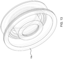
- the hydraulic drive mechanism 19 includes a hydraulic cylinder part 19a that causes a rod 19b and a piston 19c that are supported so as to be able to move linearly to reciprocate in response to change in working-fluid hydraulic pressure.
- a system in which, when the tip operation part 18 is attached to this hydraulic drive mechanism 19, the rod 19b of the hydraulic drive mechanism 19 is coupled to the rod part 18a of the tip operation part 18, and movement corresponding to the change in hydraulic pressure of the hydraulic cylinder part 19a is transferred to the forceps parts of the tip operation part 18 in synchronization.
- the hydraulic cylinder part 19a changes the volume of a working fluid chamber 19d inside the cylinder with the change in the hydraulic pressure of the working-fluid imparted from the exterior to move the piston 19c, and transfers the movement of the piston 19c to the rod part 18a of the tip operation part 18 via the rod 19b to generate an opening-closing operation of the forceps parts.
- a rolling diaphragm 19e that partitions the inside of the cylinder into an area in which the piston 19c is present and the working fluid chamber 19d while deforming correspondingly to the movement of the piston 19c, and maintains a fluid-tight state between the piston 19c and the working fluid chamber 19d (see Fig. 13 ).
- a working fluid chamber 19f is formed also in a rear end part (a right end part in Fig. 10 ) of the piston 19c of the hydraulic cylinder part 19a and, between the piston 19c and the working fluid chamber 19f of the hydraulic cylinder part 19a, there is provided a rolling diaphragm 19g that maintains the fluid-tight state between the piston 19c and the working fluid chamber 19f while deforming correspondingly to the movement of the piston 19c (see Fig. 14 ).
- the hydraulic cylinder part 19a changes the volume of the working fluid chamber 19f inside the cylinder with the change in the hydraulic pressure of the working-fluid imparted from the exterior to move the piston 19c, and transfers the movement of the piston 19c to the rod part 18a of the tip operation part 18 via the rod 19b to generate the opening-closing operation of the forceps parts.
- the rolling diaphragms 19e and 19g are formed of a stretchable material such as, e.g., silicone rubber.
- the working fluid is supplied from a hydraulic pressure supply mechanism described later.
- a sheet-shaped antibacterial cover that covers an entire slave part other than the tip operation part 18 that can be separated from the other part of the end effector 12 and can be replaced, and the tip operation part 18 of the end effector may be configured to be attachable to and detachable from the hydraulic drive mechanism 19 by using, e.g., a magnet or the like even in a state in which the cover is provided.
- the end effector 12 is configured such that the tip operation part 18 is attachable to and detachable from the hydraulic drive mechanism 19 and, besides this, the end effector 12 can also be configured such that the tip operation part 18 and the hydraulic drive mechanism 19 are integrally handled and are configured to be attachable to and detachable from the rotation support part 17, and a tip side part including the tip operation part 18 and the hydraulic drive mechanism 19 can be separated from the rotation support part 17 coupled to the other end parts of six links 13 constituting the parallel link mechanism and can be replaced and, similarly, by replacing the tip operation part 18 together with the hydraulic drive mechanism 19 with a tip operation part suitable for the surgery object or the situation, work related to the surgery can be performed efficiently.
- the configuration is not limited to the configuration in which the tip operation part 18 is configured to be attachable and detachable, and a configuration may also be adopted in which the end effector 12 is formed as an integral structure extending from the rotation support part 17 to the tip operation part 18 that cannot be separated.
- a hydraulic pressure supply mechanism 50 that supplies the working fluid to the manipulator for microscopic work 10 of the device for microscopic work 1 to change the hydraulic pressure of the working fluid includes a linear actuator 51 constituted by a mover 52 and a stator 53 having the same structures as those of the mover 15 and the stator 16 of the manipulator for microscopic work 10, and a hydraulic cylinder part 54 that is operated by this linear actuator 51.
- the hydraulic cylinder part 54 includes a columnar piston 54a and a pair of cylindrical cylinders 54b provided at both ends of the piston 54a.
- the cylinder 54b is filled with the working fluid that is not shown.
- the mover 52 of the linear actuator 51 and the piston 54a are coupled to each other by a fixing member 55, whereby the piston 54a slides in the cylinder 54b in response to the movement of the mover 52 of the linear actuator 51 and, as a result, differential hydraulic pressure is applied to the working fluid in the cylinder 54b.
- This working fluid is supplied to the manipulator for microscopic work 10.
- an operator of the device for microscopic work 1 moves the robot part 20 including the manipulator for microscopic work 10 to the vicinity of the patient 2 who lies on the surgical table 3 by moving the base 30 via the control part that is not shown, and further positions the tip operation part 18 of the manipulator for microscopic work 10 in the vicinity of an affected part of the patient 2 serving as the surgery object by moving the individual parts of the robot part 20 via the control part that is not shown.
- the operator of the device for microscopic work 1 moves each part of the imaging part 40 such that an image of an area including the vicinity of the affected part of the patient 2 can be captured by the imaging part 40 via the control part.
- the operator of the device for microscopic work 1 operates the hydraulic pressure supply mechanism 50 via the control part to adjust the hydraulic pressure of the working fluid.
- the guide member 17d of the rotation support part 17 is rotated about the center axis of the inner tubular member 17b by the hydraulic pressure adjustment by the working fluid supply of the hydraulic pressure supply mechanism 50, whereby the end effector 12 including the tip operation part 18 provided at the tip part of the rotation support part 17 is rotated, and the twisting operation of the end effector 12 is thereby implemented.
- the rotation support part 17 and the end effector 12 including the tip operation part 18 can be rotated also by the linear actuator 14 and the link 13.
- the end effector 12 is rotated (twisted) by an angle required by surgery work or the like (e.g., ⁇ 90°) by operations of only the linear actuator 14 and the link 13, there is a possibility that the link 13 may vibrate and the tip operation part 18, particularly the forceps parts may vibrate.
- the twisting (rotational) operation of the end effector 12 is performed mainly by the rotation support part 17, and the twisting operation by the linear actuator 14 and the link 13 is performed in a range in which the smooth operation is expected to be performed by the linear actuator 14 and the link 13 (about ⁇ 20° in the above-described example).
- the twisting operation by the linear actuator 14 and the link 13 is performed in a range in which the smooth operation is expected to be performed by the linear actuator 14 and the link 13 (about ⁇ 20° in the above-described example).
- the rod 19b of the end effector 12 is moved by the hydraulic pressure adjustment by the working fluid supply of the hydraulic pressure supply mechanism 50, and the rod part 18a of the tip operation part 18 is thereby moved, and the forceps parts are thereby caused to open and close.
- the twisting operation of the end effector 12 and the opening-closing operation of the forceps parts of the tip operation part 18 are performed separately from the movement of each part of the robot part 20 and the movement of the position and the orientation of the manipulator for microscopic work 10 (i.e., the movement of the position and the orientation of the end effector 12).
- the operator of the device for microscopic work 1 can operate the device for microscopic work 1 including the manipulator for microscopic work 10 according to the above procedure, can move the tip operation part 18 of the end effector 12 to hold or release a blood vessel or the like serving as the surgery object and grasp or release the surgical instrument such as a needle, and can properly operate the end effector 12 and the tip operation part 18 to cause the end effector 12 and the tip operation part 18 to execute accurate work such as, e.g., passing a needle for inosculation grasped by the tip operation part 18 through a vessel joint part in addition to the operation of moving the entire manipulator for microscopic work 10 while viewing the display part.
- the parallel link mechanism with a plurality of degrees of freedom is used as the link mechanism in which the end effector 12 is movable with respect to the base, a plurality of the linear actuators 14 that are supported on the base are used to shift one end part of each of the links so as to move the end effector 12, the linear actuator 14 is operated based on an instruction from the operator, and the position and the orientation of the end effector 12 are thereby changed, and hence it is possible to implement the accurate movement of the end effector 12 with the simple link mechanism having high rigidity in which errors are unlikely to be accumulated, it is possible to cause the end effector 12 to perform various operations related to microsurgery even with remote operations of a user who is viewing a displayed captured image, and it is possible to improve workability and reduce a burden on the user while allowing the reproduction of operations equal to manipulation of a skilled surgeon.
- the rotation operation of the end effector 12 and the tip operation part 18 that executes the actual handling of the surgery object or the surgical instrument are configured to be hydraulically driven, whereby it is not necessary to provide a sensor for power detection used in the case of motor drive in the tip operation part 18, troublesome work such as calibration of a sensor becomes unnecessary, a reduction in the size of the end effector 12 is allowed, and sterilization work for the end effector 12 when the end effector 12 is used in surgery is facilitated.
- each of the rolling diaphragms 17e, 19e, and 19g is formed of a stretchable material such as, e.g., silicone rubber, and there is provided an advantage that responsiveness of each of the end effector 12 and the tip operation part 18 to minute hydraulic pressure fluctuation of the working fluid supply is excellent.
- each of the rolling diaphragms 17e, 19e, and 19g is fixed to the rotation support part 17 and the hydraulic drive mechanism 19, and hence there is provided an advantage that the rolling diaphragms 17e, 19e, and 19g are resistant to leakage of the working fluid.
- a configuration may also be adopted in which, with regard to coarse adjustment of the position or the like of the manipulator for microscopic work 10 with respect to the surgery object, the adjustment is performed by manually moving a stand and an arm such that the end effector 12 is directed to the surgery object and also has a proper distance to the surgery object in a state in which the manipulator for microscopic work 10 is temporarily mounted to and supported by the stand and the arm for supporting the manipulator for microscopic work 10.
- control lines and the information lines considered necessary for the description have been described, and all of the control lines and the information lines necessary for a product are not necessarily described. All of the configurations may be connected to each other.
Landscapes
- Engineering & Computer Science (AREA)
- Health & Medical Sciences (AREA)
- Life Sciences & Earth Sciences (AREA)
- Surgery (AREA)
- Robotics (AREA)
- Medical Informatics (AREA)
- Biomedical Technology (AREA)
- Heart & Thoracic Surgery (AREA)
- Nuclear Medicine, Radiotherapy & Molecular Imaging (AREA)
- Molecular Biology (AREA)
- Animal Behavior & Ethology (AREA)
- General Health & Medical Sciences (AREA)
- Public Health (AREA)
- Veterinary Medicine (AREA)
- Mechanical Engineering (AREA)
- Manipulator (AREA)
Priority Applications (1)
| Application Number | Priority Date | Filing Date | Title |
|---|---|---|---|
| EP25209525.2A EP4656337A3 (fr) | 2020-07-30 | 2020-07-30 | Manipulateur pour travail microscopique |
Applications Claiming Priority (1)
| Application Number | Priority Date | Filing Date | Title |
|---|---|---|---|
| PCT/JP2020/029243 WO2022024296A1 (fr) | 2020-07-30 | 2020-07-30 | Manipulateur pour travail microscopique |
Related Child Applications (1)
| Application Number | Title | Priority Date | Filing Date |
|---|---|---|---|
| EP25209525.2A Division EP4656337A3 (fr) | 2020-07-30 | 2020-07-30 | Manipulateur pour travail microscopique |
Publications (4)
| Publication Number | Publication Date |
|---|---|
| EP4190267A1 true EP4190267A1 (fr) | 2023-06-07 |
| EP4190267A4 EP4190267A4 (fr) | 2024-05-01 |
| EP4190267B1 EP4190267B1 (fr) | 2025-10-29 |
| EP4190267C0 EP4190267C0 (fr) | 2025-10-29 |
Family
ID=80037809
Family Applications (2)
| Application Number | Title | Priority Date | Filing Date |
|---|---|---|---|
| EP20947001.2A Active EP4190267B1 (fr) | 2020-07-30 | 2020-07-30 | Manipulateur pour travail microscopique |
| EP25209525.2A Pending EP4656337A3 (fr) | 2020-07-30 | 2020-07-30 | Manipulateur pour travail microscopique |
Family Applications After (1)
| Application Number | Title | Priority Date | Filing Date |
|---|---|---|---|
| EP25209525.2A Pending EP4656337A3 (fr) | 2020-07-30 | 2020-07-30 | Manipulateur pour travail microscopique |
Country Status (4)
| Country | Link |
|---|---|
| US (2) | US12582494B2 (fr) |
| EP (2) | EP4190267B1 (fr) |
| JP (4) | JP7225482B2 (fr) |
| WO (1) | WO2022024296A1 (fr) |
Families Citing this family (3)
| Publication number | Priority date | Publication date | Assignee | Title |
|---|---|---|---|---|
| CN112370164B (zh) * | 2020-11-03 | 2022-08-26 | 上海大学 | 一种空间混联骨盆骨折复位机器人 |
| US12434392B2 (en) | 2022-09-29 | 2025-10-07 | The Boeing Company | End effector for manufacturing operations in confined spaces |
| WO2025046713A1 (fr) * | 2023-08-28 | 2025-03-06 | F.Med株式会社 | Manipulateur de travail et système comprenant un manipulateur de travail |
Family Cites Families (12)
| Publication number | Priority date | Publication date | Assignee | Title |
|---|---|---|---|---|
| JPS58163805A (ja) | 1982-03-24 | 1983-09-28 | Toshio Kaneda | 円型シリンダ−を用いた把持装置 |
| JPH0712232A (ja) * | 1993-06-25 | 1995-01-17 | N Ii:Kk | 円弧状シリンダの製造方法 |
| JPH0787322A (ja) | 1993-09-09 | 1995-03-31 | Fuji Photo Film Co Ltd | 画像信号読出方法 |
| JPH09225868A (ja) | 1996-02-19 | 1997-09-02 | Aisin Seiki Co Ltd | マニピュレータ |
| KR20090057984A (ko) | 2006-09-19 | 2009-06-08 | 더 트러스티이스 오브 콜롬비아 유니버시티 인 더 시티 오브 뉴욕 | 중공형 해부학적 부유 기관 상에서의 수술을 위한 시스템, 디바이스 및 방법 |
| US9096033B2 (en) * | 2007-06-13 | 2015-08-04 | Intuitive Surgical Operations, Inc. | Surgical system instrument sterile adapter |
| US20120095596A1 (en) * | 2010-10-14 | 2012-04-19 | Special Applications Technology, Inc. | Modular apparatuses |
| KR102237597B1 (ko) | 2014-02-18 | 2021-04-07 | 삼성전자주식회사 | 수술 로봇용 마스터 장치 및 그 제어 방법 |
| CN104398303B (zh) * | 2014-10-28 | 2016-09-07 | 浙江理工大学 | 一种用于微创手术的混联机械手 |
| JP6817607B2 (ja) * | 2015-11-05 | 2021-01-20 | 国立大学法人九州大学 | 微細作業支援システム及び微細作業用マニピュレータ |
| WO2018144654A1 (fr) | 2017-01-31 | 2018-08-09 | Transenterix Surgical, Inc. | Système d'entraînement d'instrument hydraulique pour chirurgie mini-invasive |
| JP7167522B2 (ja) * | 2018-07-27 | 2022-11-09 | セイコーエプソン株式会社 | ロボットアーム |
-
2020
- 2020-07-30 WO PCT/JP2020/029243 patent/WO2022024296A1/fr not_active Ceased
- 2020-07-30 US US18/018,744 patent/US12582494B2/en active Active
- 2020-07-30 EP EP20947001.2A patent/EP4190267B1/fr active Active
- 2020-07-30 EP EP25209525.2A patent/EP4656337A3/fr active Pending
- 2020-07-30 JP JP2021523331A patent/JP7225482B2/ja active Active
-
2022
- 2022-11-28 JP JP2022189006A patent/JP7584807B2/ja active Active
-
2024
- 2024-10-29 JP JP2024189973A patent/JP7786765B2/ja active Active
-
2025
- 2025-08-22 JP JP2025139118A patent/JP2025169411A/ja active Pending
- 2025-12-16 US US19/420,811 patent/US20260102217A1/en active Pending
Also Published As
| Publication number | Publication date |
|---|---|
| WO2022024296A1 (fr) | 2022-02-03 |
| EP4656337A2 (fr) | 2025-12-03 |
| JP2025003706A (ja) | 2025-01-09 |
| EP4190267A4 (fr) | 2024-05-01 |
| EP4190267B1 (fr) | 2025-10-29 |
| US12582494B2 (en) | 2026-03-24 |
| US20230355340A1 (en) | 2023-11-09 |
| JPWO2022024296A1 (fr) | 2022-02-03 |
| US20260102217A1 (en) | 2026-04-16 |
| JP7225482B2 (ja) | 2023-02-21 |
| EP4190267C0 (fr) | 2025-10-29 |
| EP4656337A3 (fr) | 2026-03-04 |
| JP2023024476A (ja) | 2023-02-16 |
| JP2025169411A (ja) | 2025-11-12 |
| JP7786765B2 (ja) | 2025-12-16 |
| JP7584807B2 (ja) | 2024-11-18 |
Similar Documents
| Publication | Publication Date | Title |
|---|---|---|
| US20260102217A1 (en) | Manipulator for microscopic work | |
| US12161435B2 (en) | Computer-assisted teleoperated surgery systems and methods | |
| US11110594B2 (en) | Fine work assistance system and fine work manipulator | |
| JP6465365B2 (ja) | 外科用アーム | |
| EP4393653A2 (fr) | Ensemble chirurgical robotique | |
| CN113180836B (zh) | 输入装置、主操作设备及手术机器人 | |
| US20200367982A1 (en) | Computer-assisted tele-operated surgery systems and methods | |
| JP2026050387A (ja) | 微細作業用装置 | |
| CN110575260B (zh) | 一种手术机器人操作装置 | |
| EP3682835A1 (fr) | Dispositif de support et système chirurgical | |
| Hatzfeld et al. | A teleoperated platform for transanal single-port surgery: Ergonomics and workspace aspects | |
| EP1843713A1 (fr) | Systeme robotise de controle et d'actionnement micrometrique d'un endoscope | |
| WO2021192255A1 (fr) | Instrument chirurgical | |
| US12042238B2 (en) | Computer-assisted tele-operated surgery systems and methods | |
| Berkelman et al. | Control and user interface design for compact manipulators in minimally-invasive surgery |
Legal Events
| Date | Code | Title | Description |
|---|---|---|---|
| STAA | Information on the status of an ep patent application or granted ep patent |
Free format text: STATUS: THE INTERNATIONAL PUBLICATION HAS BEEN MADE |
|
| PUAI | Public reference made under article 153(3) epc to a published international application that has entered the european phase |
Free format text: ORIGINAL CODE: 0009012 |
|
| STAA | Information on the status of an ep patent application or granted ep patent |
Free format text: STATUS: REQUEST FOR EXAMINATION WAS MADE |
|
| 17P | Request for examination filed |
Effective date: 20230227 |
|
| AK | Designated contracting states |
Kind code of ref document: A1 Designated state(s): AL AT BE BG CH CY CZ DE DK EE ES FI FR GB GR HR HU IE IS IT LI LT LU LV MC MK MT NL NO PL PT RO RS SE SI SK SM TR |
|
| DAV | Request for validation of the european patent (deleted) | ||
| DAX | Request for extension of the european patent (deleted) | ||
| A4 | Supplementary search report drawn up and despatched |
Effective date: 20240402 |
|
| RIC1 | Information provided on ipc code assigned before grant |
Ipc: B25J 17/02 20060101ALI20240325BHEP Ipc: B25J 9/14 20060101ALI20240325BHEP Ipc: B25J 9/00 20060101ALI20240325BHEP Ipc: B25J 7/00 20060101ALI20240325BHEP Ipc: A61B 34/00 20160101ALI20240325BHEP Ipc: A61B 34/30 20160101AFI20240325BHEP |
|
| GRAP | Despatch of communication of intention to grant a patent |
Free format text: ORIGINAL CODE: EPIDOSNIGR1 |
|
| STAA | Information on the status of an ep patent application or granted ep patent |
Free format text: STATUS: GRANT OF PATENT IS INTENDED |
|
| RIC1 | Information provided on ipc code assigned before grant |
Ipc: B25J 17/02 20060101ALI20250521BHEP Ipc: B25J 9/14 20060101ALI20250521BHEP Ipc: B25J 9/00 20060101ALI20250521BHEP Ipc: B25J 7/00 20060101ALI20250521BHEP Ipc: A61B 34/00 20160101ALI20250521BHEP Ipc: A61B 34/30 20160101AFI20250521BHEP |
|
| INTG | Intention to grant announced |
Effective date: 20250530 |
|
| GRAS | Grant fee paid |
Free format text: ORIGINAL CODE: EPIDOSNIGR3 |
|
| GRAA | (expected) grant |
Free format text: ORIGINAL CODE: 0009210 |
|
| STAA | Information on the status of an ep patent application or granted ep patent |
Free format text: STATUS: THE PATENT HAS BEEN GRANTED |
|
| AK | Designated contracting states |
Kind code of ref document: B1 Designated state(s): AL AT BE BG CH CY CZ DE DK EE ES FI FR GB GR HR HU IE IS IT LI LT LU LV MC MK MT NL NO PL PT RO RS SE SI SK SM TR |
|
| RAP3 | Party data changed (applicant data changed or rights of an application transferred) |
Owner name: F. MED CO., LTD. |
|
| REG | Reference to a national code |
Ref country code: CH Ref legal event code: F10 Free format text: ST27 STATUS EVENT CODE: U-0-0-F10-F00 (AS PROVIDED BY THE NATIONAL OFFICE) Effective date: 20251029 Ref country code: GB Ref legal event code: FG4D |
|
| RIN1 | Information on inventor provided before grant (corrected) |
Inventor name: OGURI, SUSUMU |
|
| REG | Reference to a national code |
Ref country code: DE Ref legal event code: R096 Ref document number: 602020061485 Country of ref document: DE |
|
| REG | Reference to a national code |
Ref country code: IE Ref legal event code: FG4D |
|
| U01 | Request for unitary effect filed |
Effective date: 20251127 |
|
| U07 | Unitary effect registered |
Designated state(s): AT BE BG DE DK EE FI FR IT LT LU LV MT NL PT RO SE SI Effective date: 20251204 |
|
| PG25 | Lapsed in a contracting state [announced via postgrant information from national office to epo] |
Ref country code: ES Free format text: LAPSE BECAUSE OF FAILURE TO SUBMIT A TRANSLATION OF THE DESCRIPTION OR TO PAY THE FEE WITHIN THE PRESCRIBED TIME-LIMIT Effective date: 20251029 |
|
| PG25 | Lapsed in a contracting state [announced via postgrant information from national office to epo] |
Ref country code: NO Free format text: LAPSE BECAUSE OF FAILURE TO SUBMIT A TRANSLATION OF THE DESCRIPTION OR TO PAY THE FEE WITHIN THE PRESCRIBED TIME-LIMIT Effective date: 20260129 |
|
| PG25 | Lapsed in a contracting state [announced via postgrant information from national office to epo] |
Ref country code: HR Free format text: LAPSE BECAUSE OF FAILURE TO SUBMIT A TRANSLATION OF THE DESCRIPTION OR TO PAY THE FEE WITHIN THE PRESCRIBED TIME-LIMIT Effective date: 20251029 |
|
| PG25 | Lapsed in a contracting state [announced via postgrant information from national office to epo] |
Ref country code: RS Free format text: LAPSE BECAUSE OF FAILURE TO SUBMIT A TRANSLATION OF THE DESCRIPTION OR TO PAY THE FEE WITHIN THE PRESCRIBED TIME-LIMIT Effective date: 20260129 |
|
| PG25 | Lapsed in a contracting state [announced via postgrant information from national office to epo] |
Ref country code: IS Free format text: LAPSE BECAUSE OF FAILURE TO SUBMIT A TRANSLATION OF THE DESCRIPTION OR TO PAY THE FEE WITHIN THE PRESCRIBED TIME-LIMIT Effective date: 20260228 |
|
| PG25 | Lapsed in a contracting state [announced via postgrant information from national office to epo] |
Ref country code: PL Free format text: LAPSE BECAUSE OF FAILURE TO SUBMIT A TRANSLATION OF THE DESCRIPTION OR TO PAY THE FEE WITHIN THE PRESCRIBED TIME-LIMIT Effective date: 20251029 |