EP4190389A1 - Système de régulation de débit - Google Patents
Système de régulation de débit Download PDFInfo
- Publication number
- EP4190389A1 EP4190389A1 EP22215365.2A EP22215365A EP4190389A1 EP 4190389 A1 EP4190389 A1 EP 4190389A1 EP 22215365 A EP22215365 A EP 22215365A EP 4190389 A1 EP4190389 A1 EP 4190389A1
- Authority
- EP
- European Patent Office
- Prior art keywords
- tube
- bobbins
- clamping mechanism
- bobbin
- flow rate
- Prior art date
- Legal status (The legal status is an assumption and is not a legal conclusion. Google has not performed a legal analysis and makes no representation as to the accuracy of the status listed.)
- Granted
Links
Images

Classifications
-
- A—HUMAN NECESSITIES
- A61—MEDICAL OR VETERINARY SCIENCE; HYGIENE
- A61M—DEVICES FOR INTRODUCING MEDIA INTO, OR ONTO, THE BODY; DEVICES FOR TRANSDUCING BODY MEDIA OR FOR TAKING MEDIA FROM THE BODY; DEVICES FOR PRODUCING OR ENDING SLEEP OR STUPOR
- A61M39/00—Tubes, tube connectors, tube couplings, valves, access sites or the like, specially adapted for medical use
- A61M39/22—Valves or arrangement of valves
- A61M39/28—Clamping means for squeezing flexible tubes, e.g. roller clamps
-
- A—HUMAN NECESSITIES
- A61—MEDICAL OR VETERINARY SCIENCE; HYGIENE
- A61M—DEVICES FOR INTRODUCING MEDIA INTO, OR ONTO, THE BODY; DEVICES FOR TRANSDUCING BODY MEDIA OR FOR TAKING MEDIA FROM THE BODY; DEVICES FOR PRODUCING OR ENDING SLEEP OR STUPOR
- A61M5/00—Devices for bringing media into the body in a subcutaneous, intra-vascular or intramuscular way; Accessories therefor, e.g. filling or cleaning devices, arm-rests
- A61M5/14—Infusion devices, e.g. infusing by gravity; Blood infusion; Accessories therefor
- A61M5/168—Means for controlling media flow to the body or for metering media to the body, e.g. drip meters, counters ; Monitoring media flow to the body
- A61M5/16877—Adjusting flow; Devices for setting a flow rate
- A61M5/16881—Regulating valves
-
- A—HUMAN NECESSITIES
- A61—MEDICAL OR VETERINARY SCIENCE; HYGIENE
- A61M—DEVICES FOR INTRODUCING MEDIA INTO, OR ONTO, THE BODY; DEVICES FOR TRANSDUCING BODY MEDIA OR FOR TAKING MEDIA FROM THE BODY; DEVICES FOR PRODUCING OR ENDING SLEEP OR STUPOR
- A61M39/00—Tubes, tube connectors, tube couplings, valves, access sites or the like, specially adapted for medical use
- A61M39/22—Valves or arrangement of valves
- A61M39/28—Clamping means for squeezing flexible tubes, e.g. roller clamps
- A61M39/281—Automatic tube cut-off devices, e.g. squeezing tube on detection of air
-
- A—HUMAN NECESSITIES
- A61—MEDICAL OR VETERINARY SCIENCE; HYGIENE
- A61M—DEVICES FOR INTRODUCING MEDIA INTO, OR ONTO, THE BODY; DEVICES FOR TRANSDUCING BODY MEDIA OR FOR TAKING MEDIA FROM THE BODY; DEVICES FOR PRODUCING OR ENDING SLEEP OR STUPOR
- A61M39/00—Tubes, tube connectors, tube couplings, valves, access sites or the like, specially adapted for medical use
- A61M39/22—Valves or arrangement of valves
- A61M39/28—Clamping means for squeezing flexible tubes, e.g. roller clamps
- A61M39/285—Cam clamps, e.g. roller clamps with eccentric axis
-
- A—HUMAN NECESSITIES
- A61—MEDICAL OR VETERINARY SCIENCE; HYGIENE
- A61M—DEVICES FOR INTRODUCING MEDIA INTO, OR ONTO, THE BODY; DEVICES FOR TRANSDUCING BODY MEDIA OR FOR TAKING MEDIA FROM THE BODY; DEVICES FOR PRODUCING OR ENDING SLEEP OR STUPOR
- A61M39/00—Tubes, tube connectors, tube couplings, valves, access sites or the like, specially adapted for medical use
- A61M39/22—Valves or arrangement of valves
- A61M39/28—Clamping means for squeezing flexible tubes, e.g. roller clamps
- A61M39/286—Wedge clamps, e.g. roller clamps with inclined guides
-
- A—HUMAN NECESSITIES
- A61—MEDICAL OR VETERINARY SCIENCE; HYGIENE
- A61M—DEVICES FOR INTRODUCING MEDIA INTO, OR ONTO, THE BODY; DEVICES FOR TRANSDUCING BODY MEDIA OR FOR TAKING MEDIA FROM THE BODY; DEVICES FOR PRODUCING OR ENDING SLEEP OR STUPOR
- A61M39/00—Tubes, tube connectors, tube couplings, valves, access sites or the like, specially adapted for medical use
- A61M39/22—Valves or arrangement of valves
- A61M39/28—Clamping means for squeezing flexible tubes, e.g. roller clamps
- A61M39/286—Wedge clamps, e.g. roller clamps with inclined guides
- A61M39/287—Wedge formed by a slot having varying width, e.g. slide clamps
-
- A—HUMAN NECESSITIES
- A61—MEDICAL OR VETERINARY SCIENCE; HYGIENE
- A61M—DEVICES FOR INTRODUCING MEDIA INTO, OR ONTO, THE BODY; DEVICES FOR TRANSDUCING BODY MEDIA OR FOR TAKING MEDIA FROM THE BODY; DEVICES FOR PRODUCING OR ENDING SLEEP OR STUPOR
- A61M2205/00—General characteristics of the apparatus
- A61M2205/33—Controlling, regulating or measuring
- A61M2205/3331—Pressure; Flow
- A61M2205/3334—Measuring or controlling the flow rate
-
- A—HUMAN NECESSITIES
- A61—MEDICAL OR VETERINARY SCIENCE; HYGIENE
- A61M—DEVICES FOR INTRODUCING MEDIA INTO, OR ONTO, THE BODY; DEVICES FOR TRANSDUCING BODY MEDIA OR FOR TAKING MEDIA FROM THE BODY; DEVICES FOR PRODUCING OR ENDING SLEEP OR STUPOR
- A61M2205/00—General characteristics of the apparatus
- A61M2205/50—General characteristics of the apparatus with microprocessors or computers
-
- F—MECHANICAL ENGINEERING; LIGHTING; HEATING; WEAPONS; BLASTING
- F16—ENGINEERING ELEMENTS AND UNITS; GENERAL MEASURES FOR PRODUCING AND MAINTAINING EFFECTIVE FUNCTIONING OF MACHINES OR INSTALLATIONS; THERMAL INSULATION IN GENERAL
- F16K—VALVES; TAPS; COCKS; ACTUATING-FLOATS; DEVICES FOR VENTING OR AERATING
- F16K7/00—Diaphragm valves or cut-off apparatus, e.g. with a member deformed, but not moved bodily, to close the passage ; Pinch valves
- F16K7/02—Diaphragm valves or cut-off apparatus, e.g. with a member deformed, but not moved bodily, to close the passage ; Pinch valves with tubular diaphragm
- F16K7/04—Diaphragm valves or cut-off apparatus, e.g. with a member deformed, but not moved bodily, to close the passage ; Pinch valves with tubular diaphragm constrictable by external radial force
- F16K7/06—Diaphragm valves or cut-off apparatus, e.g. with a member deformed, but not moved bodily, to close the passage ; Pinch valves with tubular diaphragm constrictable by external radial force by means of a screw-spindle, cam, or other mechanical means
- F16K7/065—Cam clamps
Definitions
- flexible tubes are typically used to transport fluids such as blood or solutions.
- a convenient way to restrict the flow without risking contamination by direct contact with a fluid is to squeeze a flexible tube using a clamp.
- Usual clamps are operated manually and releasable to remove the flow restriction on demand.
- the tube-engaging surface portion is the part of the bobbins that comes into contact with a tube to be provided. It will be understood that the bobbins are installed side by side such that the tube-engaging surface portions may face each other.
- the surface portion may be a groove extending circumferentially around at least part of the circumference of a bobbin. A tube may be held between the tube-engaging surface portions, e.g., between the grooves, of two bobbins.
- the present invention employs a dual-bobbins mechanism to gradually squeeze a tube to increase a flow restriction, gradually, to allow the flow rate to be reduced and stopped.
- the mechanism described herein comprises a configuration wherein at least one tube-engaging surface portion comprises a shape suitable to deform a tube sufficiently to affect flow through the tube. More specifically, the configuration is suitable to affect the flow rate through the tube. In embodiments, the configuration is suitable to alter (i.e., to reduce or increase) the flow rate by at least 0.5 Ipm. The configuration may allow the flow through a tube to be practically blocked.
- the clamping mechanism comprises a friction-reducing arrangement to reduce the grip of the bobbins as they deform the tube.
- the clamping mechanism comprises a translatable carrier on which the bobbins are disposed to allow the bobbins to move along the tube as the bobbins are rotated.
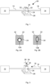
- FIG. 2A illustrates the tube 10 extending through the free space between the grooves 24 of the bobbins 22 and 32.
- two bobbins 22 and 32 are shown in an orientation in which two semi-circular portions of the grooves 24 face each other to define an approximately circular free space between them.
- a tube 10 having a circular cross-section is held in a non-squeezed condition 10A.
- Figure 2B the two bobbins 22 and 32 of Figure 2A are rotated to an orientation in which the shape of the grooves 24 is altered relative to the Figure 2A orientation.
- both grooves 24 are flatter, and the free space between the grooves 24 is correspondingly reduced (more oval).
- the tube 10 is squeezed to a condition 10B. By sufficiently squeezing the tube 10, the flow rate through it can be affected.
- the first bobbin 22 comprises a marker 26 merely for illustration purposes, to better visualise a rotation of the first bobbin between Figures.
- the marker 26 is not necessarily present in an actual embodiment.
- the tube 10 is gripped more tightly and squeezed.
- the tight grip of the bobbins may cause the tube 10 to be pulled in the direction of the counter-rotation, as is indicated by arrow 18, away from the source 14. This puts a strain on the connection 16 and may even lead to the connection 16 detaching from the source 14, as indicated in Figure 3 .
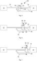
- the bobbins are configured to engage the tube in a synchronised manner.
- the first bobbin 22 and the second bobbin 32 have been counter-rotated, as indicated by a first arrow 34 for the first bobbin 22 and by a second arrow 36 for the second bobbin 32.
- the bobbins are also translated by an amount proportionate to the degree of rotation along the frame 40.
- the translational movement of the bobbins along the frame 40 is indicated by an arrow 18.
- the driver is not shown in Figure 6 , it will be understood that the rotation of each bobbin may be effected by a lead screw driving the carriage 46 and that each bobbin may be coupled via a gear to a toothed rack of the frame 40, and thus each bobbin rotates as the carriage 46 is moved.
- the free space between the grooves is reduced relative to Figure 5 such that flow through the tube is restricted, in principle corresponding to the configuration shown in Figure 2B . For instance, the flow through the tube may be restricted to no more than 2 Ipm.
- the pressure value may be measured using established pressure sensors, such as a Swan-Ganz catheter. Such pressure sensors are used routinely during heart surgery. Pressure values may be provided as an input to the controller.
Landscapes
- Health & Medical Sciences (AREA)
- Heart & Thoracic Surgery (AREA)
- Animal Behavior & Ethology (AREA)
- General Health & Medical Sciences (AREA)
- Anesthesiology (AREA)
- Biomedical Technology (AREA)
- Hematology (AREA)
- Life Sciences & Earth Sciences (AREA)
- Veterinary Medicine (AREA)
- Engineering & Computer Science (AREA)
- Public Health (AREA)
- Pulmonology (AREA)
- Physics & Mathematics (AREA)
- Fluid Mechanics (AREA)
- Vascular Medicine (AREA)
- External Artificial Organs (AREA)
- Infusion, Injection, And Reservoir Apparatuses (AREA)
Priority Applications (1)
| Application Number | Priority Date | Filing Date | Title |
|---|---|---|---|
| EP25190983.4A EP4613320A3 (fr) | 2016-03-01 | 2017-02-28 | Système de régulation de débit |
Applications Claiming Priority (3)
| Application Number | Priority Date | Filing Date | Title |
|---|---|---|---|
| GB1603536.2A GB2547900B (en) | 2016-03-01 | 2016-03-01 | Flow control system |
| PCT/GB2017/050535 WO2017149290A1 (fr) | 2016-03-01 | 2017-02-28 | Système de régulation de débit |
| EP17709747.4A EP3423145B1 (fr) | 2016-03-01 | 2017-02-28 | Système de régulation de débit |
Related Parent Applications (2)
| Application Number | Title | Priority Date | Filing Date |
|---|---|---|---|
| EP17709747.4A Division EP3423145B1 (fr) | 2016-03-01 | 2017-02-28 | Système de régulation de débit |
| EP17709747.4A Division-Into EP3423145B1 (fr) | 2016-03-01 | 2017-02-28 | Système de régulation de débit |
Related Child Applications (2)
| Application Number | Title | Priority Date | Filing Date |
|---|---|---|---|
| EP25190983.4A Division-Into EP4613320A3 (fr) | 2016-03-01 | 2017-02-28 | Système de régulation de débit |
| EP25190983.4A Division EP4613320A3 (fr) | 2016-03-01 | 2017-02-28 | Système de régulation de débit |
Publications (2)
| Publication Number | Publication Date |
|---|---|
| EP4190389A1 true EP4190389A1 (fr) | 2023-06-07 |
| EP4190389B1 EP4190389B1 (fr) | 2025-12-17 |
Family
ID=55807113
Family Applications (3)
| Application Number | Title | Priority Date | Filing Date |
|---|---|---|---|
| EP17709747.4A Active EP3423145B1 (fr) | 2016-03-01 | 2017-02-28 | Système de régulation de débit |
| EP22215365.2A Active EP4190389B1 (fr) | 2016-03-01 | 2017-02-28 | Système de régulation de débit |
| EP25190983.4A Pending EP4613320A3 (fr) | 2016-03-01 | 2017-02-28 | Système de régulation de débit |
Family Applications Before (1)
| Application Number | Title | Priority Date | Filing Date |
|---|---|---|---|
| EP17709747.4A Active EP3423145B1 (fr) | 2016-03-01 | 2017-02-28 | Système de régulation de débit |
Family Applications After (1)
| Application Number | Title | Priority Date | Filing Date |
|---|---|---|---|
| EP25190983.4A Pending EP4613320A3 (fr) | 2016-03-01 | 2017-02-28 | Système de régulation de débit |
Country Status (4)
| Country | Link |
|---|---|
| US (2) | US11376412B2 (fr) |
| EP (3) | EP3423145B1 (fr) |
| GB (1) | GB2547900B (fr) |
| WO (1) | WO2017149290A1 (fr) |
Families Citing this family (6)
| Publication number | Priority date | Publication date | Assignee | Title |
|---|---|---|---|---|
| DE102016208677A1 (de) * | 2016-05-19 | 2017-11-23 | B. Braun Melsungen Ag | Durchflussregeleinrichtung für eine Schlauchleitung eines medizinischen Infusionssystems |
| JP7053630B2 (ja) | 2016-09-22 | 2022-04-12 | クリストファー, ジェイ プロット, | 血液の体外コンディショニングのための機器及び方法 |
| AU2019290029B2 (en) * | 2018-06-20 | 2025-03-27 | Saban Ventures Pty Limited | Clamp for a medical device |
| EP3873343A4 (fr) * | 2019-03-26 | 2022-01-05 | Nuwellis, Inc. | Système de filtration de sang néonatal et pédiatrique |
| BE1028171B1 (nl) * | 2020-03-27 | 2021-10-25 | No2Covid Bv | Een regelklep voor een beademings-systeem |
| GB2631346A (en) | 2024-06-21 | 2025-01-01 | Spectrum Medical Ltd | Device for controlling fluid flow |
Citations (4)
| Publication number | Priority date | Publication date | Assignee | Title |
|---|---|---|---|---|
| US3477454A (en) * | 1967-01-09 | 1969-11-11 | Abbott Lab | Flow control device |
| EP0531137A1 (fr) * | 1991-09-03 | 1993-03-10 | Ryu Kawabe | Procédé et dispositif pour régler l'écoulement de fluide |
| US20110314977A1 (en) * | 2008-01-08 | 2011-12-29 | Lewis Howell G | Tube purging instrument |
| CH707421A1 (fr) * | 2012-12-19 | 2014-06-30 | Suisse Electronique Microtech | Vanne à étranglement. |
Family Cites Families (13)
| Publication number | Priority date | Publication date | Assignee | Title |
|---|---|---|---|---|
| US4682755A (en) * | 1985-08-23 | 1987-07-28 | Larad Equipment Corporation | Mechanical control system in flow devices |
| US5549458A (en) * | 1994-07-01 | 1996-08-27 | Baxter International Inc. | Peristaltic pump with quick release rotor head assembly |
| US6800071B1 (en) * | 1998-10-29 | 2004-10-05 | Medtronic Minimed, Inc. | Fluid reservoir piston |
| US7104275B2 (en) * | 2002-04-01 | 2006-09-12 | Emerson Electric Co. | Pinch valve |
| US6957798B1 (en) * | 2004-01-20 | 2005-10-25 | Schmidt Edward A | Pinch valve |
| US20060042631A1 (en) * | 2004-08-31 | 2006-03-02 | Martin James F | Apparatus to deliver oxygen to a patient |
| US7322556B2 (en) * | 2005-09-08 | 2008-01-29 | Bernstein Robert E | Pinch valve for regulating fluid flow |
| US7246786B1 (en) * | 2005-11-04 | 2007-07-24 | Custom Valves, Llc | Heavy duty pinch valve |
| FI120472B (fi) * | 2006-06-06 | 2009-10-30 | Metso Automation Oy | Ohjausmenetelmä ja ohjausjärjestelmä virtausta säätävää venttiiliä varten |
| DE102009026592B4 (de) * | 2009-05-29 | 2014-08-28 | Sorin Group Deutschland Gmbh | Vorrichtung zur Festlegung des venösen Zuflusses zu einem Blutreservoir eines extrakorporalen Blutkreislaufs |
| DK3039500T3 (da) * | 2013-08-26 | 2019-09-23 | Spraying Systems Co | Strømningsreguleringsventilsystem og -fremgangsmåde |
| JP5839212B1 (ja) * | 2014-08-20 | 2016-01-06 | 泉工医科工業株式会社 | 血液循環システム |
| GB2537340B (en) * | 2015-01-12 | 2017-08-23 | Spectrum Medical Ltd | Pump tube retention mechanism |
-
2016
- 2016-03-01 GB GB1603536.2A patent/GB2547900B/en active Active
-
2017
- 2017-02-28 US US16/080,565 patent/US11376412B2/en active Active
- 2017-02-28 EP EP17709747.4A patent/EP3423145B1/fr active Active
- 2017-02-28 EP EP22215365.2A patent/EP4190389B1/fr active Active
- 2017-02-28 EP EP25190983.4A patent/EP4613320A3/fr active Pending
- 2017-02-28 WO PCT/GB2017/050535 patent/WO2017149290A1/fr not_active Ceased
-
2022
- 2022-06-08 US US17/835,709 patent/US12036381B2/en active Active
Patent Citations (4)
| Publication number | Priority date | Publication date | Assignee | Title |
|---|---|---|---|---|
| US3477454A (en) * | 1967-01-09 | 1969-11-11 | Abbott Lab | Flow control device |
| EP0531137A1 (fr) * | 1991-09-03 | 1993-03-10 | Ryu Kawabe | Procédé et dispositif pour régler l'écoulement de fluide |
| US20110314977A1 (en) * | 2008-01-08 | 2011-12-29 | Lewis Howell G | Tube purging instrument |
| CH707421A1 (fr) * | 2012-12-19 | 2014-06-30 | Suisse Electronique Microtech | Vanne à étranglement. |
Also Published As
| Publication number | Publication date |
|---|---|
| EP4190389B1 (fr) | 2025-12-17 |
| US12036381B2 (en) | 2024-07-16 |
| GB201603536D0 (en) | 2016-04-13 |
| GB2547900B (en) | 2018-03-28 |
| US20190321621A1 (en) | 2019-10-24 |
| EP4613320A2 (fr) | 2025-09-10 |
| US20220323741A1 (en) | 2022-10-13 |
| EP3423145A1 (fr) | 2019-01-09 |
| GB2547900A (en) | 2017-09-06 |
| EP3423145B1 (fr) | 2023-02-15 |
| WO2017149290A1 (fr) | 2017-09-08 |
| EP4613320A3 (fr) | 2025-11-19 |
| US11376412B2 (en) | 2022-07-05 |
Similar Documents
| Publication | Publication Date | Title |
|---|---|---|
| US12036381B2 (en) | Flow control system | |
| US5429486A (en) | Single roller blood pump and oxygenator system | |
| EP3377143B1 (fr) | Système de régulation du débit sanguin dans un circuit extracorporel d'oxygénation du sang | |
| CN108136098B (zh) | 用于执行腹膜超滤的设备 | |
| JP2003533243A (ja) | 腹膜透析治療をモニタリングおよび制御するための方法および装置 | |
| NO833440L (no) | Hemodialyseanordning | |
| EP3641849B1 (fr) | Systèmes et procédés permettant d'incorporer la pression du patient dans un système d'administration de fluide médical | |
| CN118512285B (zh) | 一种可控弯主动脉瓣膜输送系统 | |
| JP2002534223A (ja) | 連続腎臓代償療法における熱損失補償 | |
| US20250339615A1 (en) | Circular roller clamp assembly | |
| WO2019142925A1 (fr) | Dispositif de réglage de détecteur de pression | |
| EP3873561B1 (fr) | Verrouillage d'évent | |
| JP2019157653A (ja) | ローラーポンプ及びその制御方法 | |
| CN223668390U (zh) | 血液净化用自动补液装置 | |
| CN215995044U (zh) | 一种压力可调节性导管 | |
| CN120771375A (zh) | 一种神经外科头部手术引流装置 | |
| WO2024251689A1 (fr) | Pompe de perfusion à détection d'occlusion automatique et réglage commandé | |
| JP2025518511A (ja) | 強化された弁特徴を有する透析システム | |
| CN110604841A (zh) | 一种肾内科临床用血液透析转换装置 | |
| CN120884426A (zh) | 一种基于双腔道精准控温的创伤患者体腔复温方法、装置及存储介质 | |
| CN118987475A (zh) | 一种多球囊的经皮机械循环辅助装置 |
Legal Events
| Date | Code | Title | Description |
|---|---|---|---|
| PUAI | Public reference made under article 153(3) epc to a published international application that has entered the european phase |
Free format text: ORIGINAL CODE: 0009012 |
|
| STAA | Information on the status of an ep patent application or granted ep patent |
Free format text: STATUS: THE APPLICATION HAS BEEN PUBLISHED |
|
| AC | Divisional application: reference to earlier application |
Ref document number: 3423145 Country of ref document: EP Kind code of ref document: P |
|
| AK | Designated contracting states |
Kind code of ref document: A1 Designated state(s): AL AT BE BG CH CY CZ DE DK EE ES FI FR GB GR HR HU IE IS IT LI LT LU LV MC MK MT NL NO PL PT RO RS SE SI SK SM TR |
|
| STAA | Information on the status of an ep patent application or granted ep patent |
Free format text: STATUS: REQUEST FOR EXAMINATION WAS MADE |
|
| 17P | Request for examination filed |
Effective date: 20230621 |
|
| RBV | Designated contracting states (corrected) |
Designated state(s): AL AT BE BG CH CY CZ DE DK EE ES FI FR GB GR HR HU IE IS IT LI LT LU LV MC MK MT NL NO PL PT RO RS SE SI SK SM TR |
|
| GRAP | Despatch of communication of intention to grant a patent |
Free format text: ORIGINAL CODE: EPIDOSNIGR1 |
|
| STAA | Information on the status of an ep patent application or granted ep patent |
Free format text: STATUS: GRANT OF PATENT IS INTENDED |
|
| GRAJ | Information related to disapproval of communication of intention to grant by the applicant or resumption of examination proceedings by the epo deleted |
Free format text: ORIGINAL CODE: EPIDOSDIGR1 |
|
| STAA | Information on the status of an ep patent application or granted ep patent |
Free format text: STATUS: REQUEST FOR EXAMINATION WAS MADE |
|
| GRAP | Despatch of communication of intention to grant a patent |
Free format text: ORIGINAL CODE: EPIDOSNIGR1 |
|
| INTG | Intention to grant announced |
Effective date: 20250708 |
|
| STAA | Information on the status of an ep patent application or granted ep patent |
Free format text: STATUS: GRANT OF PATENT IS INTENDED |
|
| INTC | Intention to grant announced (deleted) | ||
| P01 | Opt-out of the competence of the unified patent court (upc) registered |
Free format text: CASE NUMBER: UPC_APP_0218_4190389/2025 Effective date: 20250711 |
|
| INTG | Intention to grant announced |
Effective date: 20250807 |
|
| GRAS | Grant fee paid |
Free format text: ORIGINAL CODE: EPIDOSNIGR3 |
|
| GRAA | (expected) grant |
Free format text: ORIGINAL CODE: 0009210 |
|
| STAA | Information on the status of an ep patent application or granted ep patent |
Free format text: STATUS: THE PATENT HAS BEEN GRANTED |
|
| AC | Divisional application: reference to earlier application |
Ref document number: 3423145 Country of ref document: EP Kind code of ref document: P |
|
| AK | Designated contracting states |
Kind code of ref document: B1 Designated state(s): AL AT BE BG CH CY CZ DE DK EE ES FI FR GB GR HR HU IE IS IT LI LT LU LV MC MK MT NL NO PL PT RO RS SE SI SK SM TR |
|
| REG | Reference to a national code |
Ref country code: CH Ref legal event code: F10 Free format text: ST27 STATUS EVENT CODE: U-0-0-F10-F00 (AS PROVIDED BY THE NATIONAL OFFICE) Effective date: 20251217 Ref country code: GB Ref legal event code: FG4D |
|
| REG | Reference to a national code |
Ref country code: DE Ref legal event code: R096 Ref document number: 602017093233 Country of ref document: DE |
|
| PGFP | Annual fee paid to national office [announced via postgrant information from national office to epo] |
Ref country code: FR Payment date: 20251231 Year of fee payment: 10 |
|
| PGFP | Annual fee paid to national office [announced via postgrant information from national office to epo] |
Ref country code: GB Payment date: 20260106 Year of fee payment: 10 |
|
| REG | Reference to a national code |
Ref country code: LT Ref legal event code: MG9D |
|
| PG25 | Lapsed in a contracting state [announced via postgrant information from national office to epo] |
Ref country code: NO Free format text: LAPSE BECAUSE OF FAILURE TO SUBMIT A TRANSLATION OF THE DESCRIPTION OR TO PAY THE FEE WITHIN THE PRESCRIBED TIME-LIMIT Effective date: 20260317 |
|
| PGFP | Annual fee paid to national office [announced via postgrant information from national office to epo] |
Ref country code: DE Payment date: 20260102 Year of fee payment: 10 |
|
| PG25 | Lapsed in a contracting state [announced via postgrant information from national office to epo] |
Ref country code: HR Free format text: LAPSE BECAUSE OF FAILURE TO SUBMIT A TRANSLATION OF THE DESCRIPTION OR TO PAY THE FEE WITHIN THE PRESCRIBED TIME-LIMIT Effective date: 20251217 Ref country code: FI Free format text: LAPSE BECAUSE OF FAILURE TO SUBMIT A TRANSLATION OF THE DESCRIPTION OR TO PAY THE FEE WITHIN THE PRESCRIBED TIME-LIMIT Effective date: 20251217 |
|
| PGFP | Annual fee paid to national office [announced via postgrant information from national office to epo] |
Ref country code: IT Payment date: 20260128 Year of fee payment: 10 |
|
| PG25 | Lapsed in a contracting state [announced via postgrant information from national office to epo] |
Ref country code: RS Free format text: LAPSE BECAUSE OF FAILURE TO SUBMIT A TRANSLATION OF THE DESCRIPTION OR TO PAY THE FEE WITHIN THE PRESCRIBED TIME-LIMIT Effective date: 20260317 |
|
| REG | Reference to a national code |
Ref country code: NL Ref legal event code: MP Effective date: 20251217 |
|
| PG25 | Lapsed in a contracting state [announced via postgrant information from national office to epo] |
Ref country code: LV Free format text: LAPSE BECAUSE OF FAILURE TO SUBMIT A TRANSLATION OF THE DESCRIPTION OR TO PAY THE FEE WITHIN THE PRESCRIBED TIME-LIMIT Effective date: 20251217 |
|
| PG25 | Lapsed in a contracting state [announced via postgrant information from national office to epo] |
Ref country code: BG Free format text: LAPSE BECAUSE OF FAILURE TO SUBMIT A TRANSLATION OF THE DESCRIPTION OR TO PAY THE FEE WITHIN THE PRESCRIBED TIME-LIMIT Effective date: 20251217 |