EP4190476A1 - Dispositif et procédé de soudage par faisceau d'électrons et de soudage par faisceau laser de tubes à paroi épaisse et de récipients sous pression - Google Patents
Dispositif et procédé de soudage par faisceau d'électrons et de soudage par faisceau laser de tubes à paroi épaisse et de récipients sous pression Download PDFInfo
- Publication number
- EP4190476A1 EP4190476A1 EP22206795.1A EP22206795A EP4190476A1 EP 4190476 A1 EP4190476 A1 EP 4190476A1 EP 22206795 A EP22206795 A EP 22206795A EP 4190476 A1 EP4190476 A1 EP 4190476A1
- Authority
- EP
- European Patent Office
- Prior art keywords
- container
- sealing plate
- pipe
- wall
- holding element
- Prior art date
- Legal status (The legal status is an assumption and is not a legal conclusion. Google has not performed a legal analysis and makes no representation as to the accuracy of the status listed.)
- Granted
Links
Images





Classifications
-
- B—PERFORMING OPERATIONS; TRANSPORTING
- B23—MACHINE TOOLS; METAL-WORKING NOT OTHERWISE PROVIDED FOR
- B23K—SOLDERING OR UNSOLDERING; WELDING; CLADDING OR PLATING BY SOLDERING OR WELDING; CUTTING BY APPLYING HEAT LOCALLY, e.g. FLAME CUTTING; WORKING BY LASER BEAM
- B23K15/00—Electron-beam welding or cutting
- B23K15/04—Electron-beam welding or cutting for welding annular seams
-
- B—PERFORMING OPERATIONS; TRANSPORTING
- B23—MACHINE TOOLS; METAL-WORKING NOT OTHERWISE PROVIDED FOR
- B23K—SOLDERING OR UNSOLDERING; WELDING; CLADDING OR PLATING BY SOLDERING OR WELDING; CUTTING BY APPLYING HEAT LOCALLY, e.g. FLAME CUTTING; WORKING BY LASER BEAM
- B23K15/00—Electron-beam welding or cutting
- B23K15/0026—Auxiliary equipment
-
- B—PERFORMING OPERATIONS; TRANSPORTING
- B23—MACHINE TOOLS; METAL-WORKING NOT OTHERWISE PROVIDED FOR
- B23K—SOLDERING OR UNSOLDERING; WELDING; CLADDING OR PLATING BY SOLDERING OR WELDING; CUTTING BY APPLYING HEAT LOCALLY, e.g. FLAME CUTTING; WORKING BY LASER BEAM
- B23K26/00—Working by laser beam, e.g. welding, cutting or boring
- B23K26/12—Working by laser beam, e.g. welding, cutting or boring in a special environment or atmosphere, e.g. in an enclosure
- B23K26/1224—Working by laser beam, e.g. welding, cutting or boring in a special environment or atmosphere, e.g. in an enclosure in vacuum
-
- B—PERFORMING OPERATIONS; TRANSPORTING
- B23—MACHINE TOOLS; METAL-WORKING NOT OTHERWISE PROVIDED FOR
- B23K—SOLDERING OR UNSOLDERING; WELDING; CLADDING OR PLATING BY SOLDERING OR WELDING; CUTTING BY APPLYING HEAT LOCALLY, e.g. FLAME CUTTING; WORKING BY LASER BEAM
- B23K26/00—Working by laser beam, e.g. welding, cutting or boring
- B23K26/20—Bonding
- B23K26/21—Bonding by welding
- B23K26/24—Seam welding
- B23K26/28—Seam welding of curved planar seams
- B23K26/282—Seam welding of curved planar seams of tube sections
Definitions
- the electron beam source When electron beam welding thick-walled components (D > 100 mm), the electron beam source must be operated in high vacuum (p ⁇ 10 -4 mbar).
- the vacuum causes, among other things, a strong decrease in the vaporization temperature of the molten material.
- a pronounced capillary can form, which makes the very deep weld seams possible in the first place.
- Bundled laser beams in high vacuum can also achieve very deep welding depths that are not possible with normal pressure.
- vacuum chambers are usually required that can completely accommodate the component to be welded in order to be able to provide the required vacuum.
- the size of the vacuum chambers required for both electron beam welding and laser beam welding in high vacuum therefore depends on the size of the component to be welded.
- large vacuum chambers are difficult or impossible to transport and there are many components which, due to their size, cannot be electron beam welded or laser beam welded in high vacuum.
- large vacuum chambers result in high costs and the time required to evacuate them also increases sharply.
- thick-walled pipes are understood to mean pressure-carrying pipes made of iron-based or nickel-based alloys which, during operation, are subjected to a pressure of at least 50 bar. however, are often also exposed to more than 200 bar.
- the operating temperatures of the pipe and/or the media in it are more than 300°C, sometimes even over 700°C.
- the wall thickness is at least 10% of the pipe diameter or at least 20 mm, but also more than 70 mm.
- the inner diameter of the pipes is between 80 mm and 5,000 mm, in particular between 120 and 1000 mm, in particular between 180 and 500 mm.
- the materials used are steel materials with a nickel content of more than 0.7% and a chromium content of more than 0.3% and in particular steels with a chromium content of more than 3.5% and in particular those with a chromium content of more than 10% and steels with a nickel content of more than that 3% in particular materials with a nickel content greater than 10%.
- the steels preferably have a carbon content of less than 0.85%, preferably less than 0.5% and particularly preferably less than 0.2%.
- the manganese content is preferably more than 0.2%, preferably more than 1%.
- the phosphorus and sulfur content is preferably less than 0.05%, in particular less than 0.01%.
- the pressure pipelines are used in particular for superheated steam, hydrogen, CO2 and ammonia.
- the DE 000019 527 048 A1 describes a system for electron beam welding that is designed to process very long workpieces using the electron beam welding process.
- the system includes a vacuum chamber that is shorter than the workpiece.
- the workpiece is not fully inserted into the system and is sealed by a sealing device at the entrance of the system.
- the electron beam gun is stationary. The workpiece is moved through the system.
- From the DE 26 32 252 A1 is a device for Manufacture of pipes or the like. known by welding individual shots using electron beam welding. Single shots are the sections of pipe that are welded together to form one long pipe.
- the electron beam source/gun is stationary and located outside the tube. The tube is rotated "under" the electron beam gun.
- a method and an arrangement for connecting open hollow bodies, such as the towers of wind energy converters, by electron beam welding are known.
- the towers are assembled on site from several sections.
- the upper end of the tower is sealed airtight with a lid.
- the lower end of the tower stands on the foundation and is sealed airtight by a seal.
- the electron beam cannon is located inside the turret.
- a vacuum is created inside the tower and then the electron beam gun is rotated through 360°, creating a circumferential weld seam.
- a major disadvantage of DE10 2009 041 383 A1 is that the volume to be evacuated is very large. It increases with the construction of the tower or the length of the pipeline, since the vacuum chamber results from closing the pipe at its ends.
- the invention is based on the DE 10 2009 041 383 A1 -
- the task of joining large thick-walled tubes or segments of pressure vessels by means of electron beam welding or laser beam welding To further simplify and improve high vacuum.
- a device for sealing a joint zone between two thick-walled pipes or container segments comprising a sealing plate and a holding element, the holding element being detachably attached to an inner wall of the pipe or the container, the sealing plate sealingly fitting into one of the Pipes or container sections can be used and the holding element is connected to the sealing plate in such a way that it absorbs the compressive forces acting on the sealing plate and introduces them into the pipe or the container segment.
- two assemblies are therefore provided, namely a sealing plate and a holding element.
- the sealing plate serves to seal off part of the inside of the pipe or the container from the environment. If a sealing plate is used on both sides of the joining zone, a vacuum chamber is created which is delimited by the sealing plates and the inner walls of the pipes or container sections to be joined.
- the desired vacuum is created by sucking out the air in the vacuum chamber.
- the electron beam of the electron beam gun or alternatively a laser beam can be directed onto the joining zone and a weld seam with the necessary depth (for example more than 100 mm) is created.
- the sealing plates according to the invention can be placed in the immediate vicinity of the joining zone inside the pipe.
- the volume of the vacuum chamber delimited by the sealing plates is relatively small. This enables or simplifies and accelerates the generation of a high vacuum.
- At least one holding element is assigned to each sealing plate.
- the holding element is braced (for example via actuators) with the inner wall of the tube and in this way a non-positive connection is established.
- the retaining element and the sealing plate are in turn connected to one another in such a way that the retaining element absorbs the compressive forces acting on the sealing plate and directs them into the pipe or the container.
- two sealing plates can also be connected to one another via one or more spacers.
- the spacers serve to compensate for the compressive forces acting on the sealing plates. Due to this force balance, the holding elements can be omitted.
- the sealing plates can be flat, they can have reinforcing ribs, or they can be curved (convex or concave).
- the sealing plates can also be designed in several parts. This makes it easier to transport the individual parts of the sealing plates to the joining zone. Only there are the sealing plates assembled from the individual parts.
- the sealing plate can then be positioned very precisely concentrically to the inner wall of the pipe, so that the (sealing) gap between pipe and sealing plate is the same size everywhere. This enables the gap to be optimally sealed over the entire circumference of the sealing plate.
- an advantageous embodiment of the invention provides that the sealing plate has at least one seal on its outer diameter which serves to seal the gap between the inner wall of the pipe or the container and the sealing plate.
- the seal can be designed as an annular hose that can be blown out, as an O-ring or as a lip seal.
- the hose or the O-ring can be inserted in a groove on the outside diameter of the sealing plate. The groove allows the seal to be firmly seated in the sealing plate. On the other hand, the seal is clamped with a certain radial tension between the groove and the tube. This improves the sealing effect.
- the seals can be designed as an inflatable hose. They are then mounted without pressure. When the sealing plate and seals are in the desired position, the inflatable seal is inflated with compressed air. As a result, they expand and seal the gap between the sealing plate and the inner wall of the pipe very well.
- two or more seals arranged one behind the other are provided on the outer diameter of the sealing plate in an advantageous embodiment of the invention.
- Each of these seals can be accommodated in a separate groove.
- the tightness of the entire system or the sealing plate is improved by connecting several seals in series.
- the pressure load on each individual seal is reduced.
- an annular vacuum chamber is formed between two adjacent seals in the sealing plate.
- a vacuum can be generated in a targeted manner via a suction line, which is between the high vacuum in the vacuum chamber and the ambient pressure. This allows small amounts of leakage to be sucked off, which get through the gap between the inner wall of the pipe and the sealing plate.
- a sufficient high vacuum can be generated, for example of 10 -4 mbar.
- Such a high vacuum is sufficient to carry out the electron beam welding or laser welding of components with large wall thicknesses (e.g. 300 mm or more) safely and effectively.
- the seals can also be designed as metal seals.
- they can be designed as bellows and the seal can be brazed or welded to the inner wall of the tube.
- the seal can be glued or welded to the inner wall of the pipe.
- the sealing lip With a suitable design of the sealing lip, it is pressed against the inner wall of the pipe by the pressure difference between the vacuum chamber and the environment; this creates a self-reinforcing sealing effect.
- the holding element is advantageously fastened in a non-positive manner to the inner wall of the pipe or of the container.
- a frictional connection is established between the holding element and the pipe, so that the holding element can also be safely introduced into the inner wall of the pipe, even with large pneumatic forces which act on the sealing plate and are transmitted from the sealing plate to the holding element.
- an electron beam gun or laser optics there is an electron beam gun or laser optics, a deflection device, a rotary drive and/or a positioning device for the electron beam gun or the laser beam on the holding element.
- This configuration is particularly advantageous when the holding element is located inside the vacuum chamber delimited by the sealing plate.
- the holding element can then be used simultaneously as a base or support for the electron beam gun or the laser optics, the deflection device of a rotary drive and/or a positioning device for the electron beam gun or the laser beam.
- the rotary drive ensures that the electron beam gun or the laser optics, when aligned radially, can pivot through 360° can perform.
- a circumferential weld seam (circumferential seam) can then be produced by rotating the electron beam gun or the laser optics once by 360° around the longitudinal axis of the pipe to be welded.
- the electron beam gun or laser optics parallel to the longitudinal axis of the pipe to be welded.
- the electron beam or laser beam is then deflected in a radial direction via a deflection device.
- the electron beam or laser beam can be guided along the joint so that the desired circumferential weld seam is produced.
- the workpieces which are approximately cylindrical at least in sections, are butt-welded.
- the electron beam gun or laser optics can be moved (rotated) in the circumferential direction to carry out the circumferential seams.
- only the electron beam can be deflected in the radial direction. This is done using a beam deflection or deflection device that includes magnets and/or suitable electrical fields. In the case of laser welding in high vacuum, the deflection takes place using one or more mirrors.
- a laser light source to direct generated laser light through a fiber optic cable or a fiber optic cable. Then the laser light source can be placed outside the vacuum chamber. The laser beam generated by the laser light source is guided into the vacuum chamber via a fiber optic cable/glass fiber line. As a result, the vacuum chamber can be kept very small. As a result, it is easier and quicker to generate the high vacuum required to join the components.
- laser beam welding - unlike electron beam welding - does not produce any X-rays.
- occupational safety is easier to ensure with laser beam welding than with electron beam welding.
- Laser optics are particularly suitable for smaller pipe diameters.
- the electron beam can then be deflected here without moving the beam source.
- the beam deflection can either be done solely by electrically driving coils or electromagnets or by mechanical rotation of a beam deflection unit that contains coils and/or electromagnets. In the latter case, this unit can also include focusing devices (coils, magnets, etc.).
- mirrors or prisms can be used to deflect the beam.
- each sealing plate associated with one or more retaining elements.
- the retaining elements are non-positively connected to the inner wall of the pipe and transfer the compressive forces acting on the sealing plate(s) into the pipe to be joined. Two constellations are possible.
- the holding element can be arranged outside the sealing plate or the vacuum chamber.
- it can be advantageous to provide an electron beam gun, a deflection device, a rotary drive and/or a positioning device for the electron beam gun or the rotary drive on the sealing plate.
- the holding element can be placed inside the sealing plate, i. H. in the vacuum chamber.
- it can be advantageous to provide an electron beam gun, a deflection device, a rotary drive and/or a positioning device for the electron beam gun or the rotary drive on the holding element.
- the sealing plate according to the invention advantageously has one or two suction lines via which a negative pressure can be generated when the sealing plate is mounted in a sealing manner in the pipe to be welded.
- a holding element is provided on both sides of the joint.
- the two sealing plates Both sides of the joining zone then delimit the vacuum chamber and the two holding elements can absorb the pneumatic forces also acting on the sealing plates.
- At least one actuator is provided on the holding element in order to press the holding element against the inner wall of the pipe or the container and to connect it with a friction fit.
- several such actuators will be provided.
- the actuators are extended radially outwards and in this way the holding element is fastened and positioned in the inner wall of the pipe with a friction fit.
- these actuators can be in the form of screws. By unscrewing the screws, the heads of the screws are pressed against the inner wall of the pipe, so that the desired frictional connection is created.
- the actuators can also be designed as pneumatic, hydraulic or electromechanical actuators. You can also be designed as wedges with hammer blows in the gap between the retaining element and the inner wall of the pipe are driven until the holding element is clamped sufficiently firmly with the inner wall of the pipe.
- a sleeve is provided on the outer wall of the pipes or container segments for sealing a joining zone, the sleeve being attached to the outer wall of the pipe or container and the Joining zone covered.
- the sleeve can have, for example, two sealing planes that are spaced apart from one another.
- the sleeve is positioned on the pipes to be joined in such a way that the joining zone is between the sealing levels of the sleeve. In this way, sealing of the joining zone against the ambient air is also achieved on the outer diameter of the joint.
- Such a cuff can be sealed in particular by sealants (silicone, rubber, O-ring, sealing cord, etc.).
- sealants silicone, rubber, O-ring, sealing cord, etc.
- Such a cuff can also have inflatable seals that allow the cuff to be used even with slightly different diameters of the pipes to be joined.
- the inflatable seals have a compressed air connection.
- the coverage of the joining zone can, for. B. done with a metal ring / a sleeve.
- This metal ring/sleeve can be attached to the outside or inside of the joining zone.
- the material of the sleeve can be used as a welding allowance
- Electron beam welding or laser beam welding can be used in high vacuum.
- the joint zone can also be sealed using a flexible (shrinkable) hose or by wrapping a (shrinkable) film around the joint zone.
- the pressure of the foil or hose on the pipe sections can be increased locally by wrapping ropes, wires, clamping devices or the like in order to achieve a better sealing effect.
- Inflatable seals can be used as a seal, particularly in the case of the sealing plates. These have the advantage that the sealing plates themselves can be made slightly smaller than the inner diameter of the pipe and can therefore be easily positioned or moved in the pipe. Only when the outer seals/sealing chambers are inflated do the sealing plates get stuck in the pipe and seal.
- silicone seals Rubber membranes, O-rings, sealing pastes or also weld seams and soldered seams can be used as seals in order to realize the vacuum chamber by means of covers in the cylindrical pipe sections to be welded.
- Suction lines are not required here. Because the joining zone is not airtight before the start of the weld, a pressure equalization takes place between the vacuum chamber and the area sealed by the sleeve. Such a cuff can have a separate vacuum connection. Then in many cases the vacuum lines of the sealing plate(s) are omitted.
- the sealing planes of the collar are weld seams (fillet welds).
- the sleeve is welded to the outside of the thick-walled pipe by hand or with an automatic welding machine. This weld is not very wide and also of very shallow depth. It only has to ensure an airtight separation between the joining zone and the environment. It is also possible to solder the sleeve to the pipes or container segments to be joined or to seal it with a sealant.
- the object on which the invention is based is also achieved by a method for joining two thick-walled pipes or container segments by means of a circumferential circumferential seam, in that a holding element is detachably attached to an inner wall of the pipe or container at least on one side of the joining zone the joining zone, a sealing plate is arranged in a sealing manner on the dividing wall of the pipe or container, that the sealing plate and the retaining element are coupled to one another in such a way that the retaining element absorbs the compressive forces acting on the sealing plate and diverts them into the pipe or into the container segment, that the Air inside the tube or the container segment is sucked out and that a peripheral seam is then produced by electron beam welding and/or laser beam welding in a vacuum.
- This process makes it possible to install a temporary vacuum chamber inside the components to be joined (thick-walled pipe or thick-walled container segments). Inside this vacuum chamber is the electron beam gun or laser optics, whose electron beam or laser beam can be directed radially outward onto the joining zone. Due to the high vacuum in the vacuum chamber, the vapor pressure in the weld is very low and it is possible to achieve weld depths of 300 mm or even 400 mm with electron beam welding or laser welding.
- a retaining element is releasably attached to the inner wall of the pipe or container on both sides of the joining zone and a sealing plate is also arranged sealingly on the inner wall of the pipe or container on the second side.
- This constellation namely with a device according to the invention on both sides of the joining zone, is particularly advantageous when two pieces of pipe are to be connected to one another and the open ends of these pieces of pipe are not to be connected, for example, by a flange cover or a welded lid can be closed.
- This configuration is also particularly advantageous for container segments.
- Preheating can be done either with a defocused electron beam/laser beam or with heating mats attached from the outside. In the latter case, it is particularly favorable if the housing of the electron beam gun or the laser optics and any other facilities of the welding device z. B. be actively cooled by water cooling.
- the welding depth of the electron beam or laser beam can be monitored and controlled by sensors, so that on the one hand reliable welding of the pipe wall is ensured, but welding does not penetrate through the cover or the seal.
- optical coherence tomography can be used as a sensor.
- X-ray detectors, temperature sensors such as thermographic cameras or ultrasonic sensors outside the pipe or inside the sleeve are also conceivable.
- a radial alignment of the electron beam gun or laser optics is preferably suitable.
- a pig is understood to be a vehicle that can be guided through the wall of a pipe and move inside it. Especially on chains, rollers, wheels or skids ...
- the pig can also accommodate the vacuum pumps as well as the high-voltage supply and control electronics. However, these can also lie outside the pipe and be connected via hoses or lines.
- This can be in the form of wire or in the form of metal rings or bands, also known as cuffs. These will be attached to the inside and/or outside of the pipes to be welded.
- the metal rings/sleeves can also be used as additional material for electron beam welding or laser beam welding in high vacuum.
- the beam is cyclically deflected by the deflection unit along the weld seam to the left and right.
- Another way to deal with tolerances is to insert an annular spacer between two pipes or pipe sections in the gap between the ends of the pipes and perform two circumferential welds.
- Both the tubes and the intermediate element can be prepared by machining and adjusted on site in order to achieve the best possible fit in the area of the joining zones. Two circumferential weld seams must then be made for welding. It is particularly advantageous if the intermediate element is so narrow/so short that it can be welded on both end faces to the two pipe sections located there in one setting and without moving the vacuum chamber.
- the device includes a control device with which the welding depth can be precisely controlled. This can be done by changing the beam power, widening, feed rate, controlling the movement of the electron beam or laser beam (the beam oscillates back and forth with a certain amplitude and possibly also frequency), pulsing (pulse duration), etc.
- OCT for example, but also X-ray sensors, ultrasonic sensors or heat sensors on the outer surface of the pipe are used as sensor elements. It is thus possible to weld pipes completely through and to cover them with just a simple single-layer weld seam use.
- the figure 1 shows two thick-walled tubes 1 in the area are to be welded together in a joining zone 3 or are already welded together.
- An inner wall of the tubes 1 is denoted by 5 .
- the outer wall is denoted by 7. If such thick-walled tubes 1 can be joined by electron beam welding or by laser beam welding in a high vacuum, this has a number of major technological and economic advantages. Electron beam welding or laser welding in high vacuum is very efficient, the heat input into the workpieces (tubes 1) is relatively low, so that the distortion of the workpieces is also low. In addition, the structure of the pipes is only changed in the immediate vicinity of the joining zone 3 or the weld seam 3 . Even at a distance of just a few millimeters from the joining zone 3, the structure of the tubes 1 is not affected by electron beam welding or laser beam welding in a high vacuum. The advantages of this welding process are well known.
- the invention now provides a device that also makes it possible to connect tubes 1 or segments of containers by means of electron beam welding or laser beam welding in a high vacuum safely and economically on site, for example on the construction site of a power plant.
- a temporary vacuum chamber must be set up for this purpose. Inside the vacuum chamber is an electron beam gun or laser beam optics, which connects the tubes 1 to one another in the area of the joining zone 3 .
- FIG 2 In the figure 2 are first exemplary embodiments device according to the invention shown.
- the figure 2 shows the two tubes 1 and the joining zone 3 analogously to FIG figure 1 .
- it is necessary to generate a high vacuum in the area of the joint 3 so that the vapor pressure of the molten material is reduced. Only then can workpieces with a thickness of well over 100 mm be welded safely, efficiently and cost-effectively.
- a (temporary) vacuum chamber 9 is produced inside the tubes 1 with the aid of the device according to the invention.
- the vacuum chamber 9 is delimited by the tubes 1 in the radial direction. In the axial direction, the vacuum chamber 9 is delimited by a sealing plate 11 on each side of the joining zone 3 .
- a holding element 13 is assigned to a sealing plate 11 according to the invention.
- the holding elements 13 on both sides of the joining zone 3 are essentially identical in construction.
- the one in the figure 2 left sealing plate 11 carries an electron beam gun or laser beam optics 15, which is aligned radially.
- Denoted at 17 is an electron beam or laser beam.
- the electron beam gun or laser optics 15 is mounted on a rotary drive 19, which in turn is attached to the figure 2 left sealing plate 11 is added.
- the rotary drive 19 When the rotary drive 19 is active, the electron beam gun or laser optics 15 rotates around the longitudinal axis of the pipes 1 to be welded, so that the electron beam or laser beam 19 sweeps over the joining zone 3 over the entire circumference of the pipes 1 when the rotary drive 19 rotates at an angle of 360°.
- the energy supply of the electron beam gun or the laser optics 15 and the rotary drive 19 and an optional positioning device, which can move the electron beam gun or the laser optics 15 in the direction of the longitudinal axis of the tubes 1, is not shown in the figures.
- the laser light source can be arranged outside of a vacuum chamber 9 and the laser light it generates can be conducted into the vacuum chamber 9 via an optical fiber/optical fiber cable.
- the sealing plate 11 on the in figure 2 Left side of the joint 3 includes two seals 21 which are spaced from each other. This results in a series connection of the seals 21 and the sealing of the vacuum chamber 9 to the surroundings of the tubes 1 is improved.
- holding elements 13 are provided according to the invention.
- the holding elements 13 are braced against the inner wall 5 of the pipes 1 in such a way that a frictional connection is created between the holding elements 13 and the pipes 11 .
- the sealing plates 11 are coupled to the holding elements 13 via supporting elements or tension rods 23 , so that the compressive forces acting on the sealing plates 11 are transmitted to the holding elements 13 .
- the holding elements 13 transfer these forces to the pipes 1 by means of the aforementioned frictional connection.
- the forces acting on the sealing plates 11 are internal forces of the pipes 1 to be joined and a very good seal of the vacuum chamber 9 inside the pipes 1 is achieved, even with large inner diameters of the pipes 1.
- annular vacuum chamber 25 is formed between the two seals 21 .
- a first vacuum line 27.1 opens into the vacuum chamber 9 and a second vacuum line 27.2 opens into the annular vacuum space 25.
- a vacuum of 10 ⁇ 1 mbar can prevail, while in the vacuum chamber 9 there is a high vacuum of, for example, 10 ⁇ 4 mbar can reign.
- the pressure difference between the high vacuum in the vacuum chamber 9 and the ambient pressure outside the tubes 1 is reduced in two stages, so that the pressure differences acting on the seals 21 are reduced.
- the negative pressure in the negative pressure space 25 is generated in that air is sucked out of the negative pressure space 25 via a suction line 27 .
- vacuum lines 27, 27.1, 27.2 are provided on only one sealing plate 11.
- this is the right-hand sealing plate 11, while the left-hand sealing plate has no suction lines, but carries the electron beam gun or laser optics 15 and the associated auxiliary units.
- a collar 29 is arranged on the outer diameter of the pipes so that no air can get into the vacuum chamber 9 from the outside through the joining zone 3 during the welding process.
- the cuff 29 can consist of several steel strips bent in a circle, which are welded airtight on the right and left with a weld seam 31 on the outer wall 7 of the pipes 1 . Together with the sleeve 29, these weld seams 31 only have the function of producing the desired tightness. They do not contribute to the strength of the joint connection / the welded connection between the both tubes 1 at. If desired, they can also be removed again after the end of the electron beam welding process.
- FIG. 2 a configuration is shown in which the holding elements 13 are arranged outside the vacuum chamber 9 .
- the compressive forces exerted on a sealing plate 11 are transmitted to the holding element 13 by means of tie rods 23 . These forces are introduced into the pipe 1 via the frictional connection between the holding element 13 and the pipe 1 .
- FIG 3 is a section through the along the line AA in the figure 2 shown.
- the sleeve 29, one of the weld seams 31, the electron beam or laser gun 15 and the sealing plate 11 with the seals 21 can be clearly seen in this view.
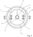
- FIG 4 a view of the holding element 13 from the left is shown.
- the cuff 29 is made in two parts. The two halves of the collar 29 are placed around the pipes 1 and tightened against the outer wall 7 of the pipes 1 with the aid of screws (no reference numerals).
- the holding element 13 comprises two shells which can be moved relative to one another via actuators.
- the actuators each include screws 33 and nuts, with the help of which the two halves of the holding element 13 can be pressed against the inner wall 5 of the tubes 1 .
- the farther the screws are unscrewed from the nuts the greater the contact pressure with which the holding element 13 is pressed against the pipe 1 and the greater the forces that can be transmitted by static friction between the holding element 13 and the pipe 1.
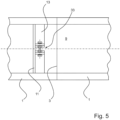
- FIG. 5 and 6 a further constellation according to the invention of a device for sealing a joining zone 3 is shown. Only one sealing plate 11 (to the left of the joining zone 3) is shown. In this exemplary embodiment, the holding element 13 is arranged inside the vacuum chamber 9 . This means that the sealing plate 11 is further away from the joining zone 3 than the holding element 13.
- the tension rods 23 can be dispensed with because the sealing plate 11 is pressed against the holding element 13 .
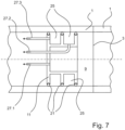
- FIG. 7 an exemplary embodiment of a sealing plate 11 is shown, which has three seals 21 arranged parallel to one another and two annular vacuum chambers 25 . Each of these vacuum spaces 25 is connected to a vacuum pump (not shown) via a separate vacuum line 27.2 and 27.3.
- the vacuum line 27.1 opens directly into the vacuum chamber 9.
- the pressure difference between the high vacuum in the vacuum chamber 9 and the environment is reduced in several stages. As a result, an even better seal is achieved and the seals 27 are less stressed.
- FIG figure 8 An analogous embodiment, however, in which the holding element 13 is arranged in the vacuum chamber 9 is shown in FIG figure 8 shown.
- This embodiment includes three separate sealing plates 11.1, 11.2 and 11.3, each with a seal 21.
- Each sealing plate 11.1, 11.2 and 11.3 has a vacuum line 27.1, 27.2 and 27.3. These vacuum lines allow the pressure difference between the high vacuum in the vacuum chamber 9 and the ambient pressure to be reduced or sealed off in several stages.
- the compressive forces acting on the sealing plate 11.3 are introduced directly into the holding element 13.
- the sealing plates 11.1 and 11.2 are connected to the retaining element 13 via tie rods 23.
- a sealing plate 11 is arranged on the right and left of the joining zone 3 . These sealing plates 11 are connected to one another via a central spacer 35 .
- the spacer 35 positions the sealing plates 11 relative to the joining zone 3 and at the same time prevents the sealing plates 11 from being skewed. Because the sealing plates 11 are the same size, the compressive forces acting on the sealing plates 11 cancel out. Therefore, the holding elements are unnecessary in this embodiment.
- sealing plates 11 in this exemplary embodiment each have two or more seals 21 and for example for an annular low-pressure chamber 25 to be present between two adjacent seals.
- the centrally arranged spacer 35 also serves as a mount/carrier for the electron beam gun or laser optics 15.
- the electron beam gun or laser optics 15 is radially aligned and arranged on a rotatable frame, which in turn is set in rotation via a rotary drive (not shown). can. This makes it possible to produce a peripheral seam in the area of the joining zone 3 .
- the electron beam gun or laser optics 15 can be aligned axially and the electron beam or laser beam can be deflected in the radial direction via a deflection device (not shown).
- the figure 10 shows a section through the figure 9 .
- the ancillary units such as the high-voltage source for the electron beam gun or the laser source for the laser optics and vacuum pumps, are fitted outside the tube 1 and connected to the components shown by hoses or cables.
- the hoses and cables outside of the vacuum chamber 9 are designed so long that, on the one hand, the units can be positioned outside of the tube.
- the lines in the vacuum area are designed with a trailing cable so that rotation of the electron beam gun or the laser optics 15 is possible.
- the figure 11 shows an exemplary embodiment in which a spacer 35 is arranged between the two sealing plates 11, which is firstly somewhat cranked and secondly can be driven off in rotation.
- the rotary drive 19 can comprise an electric motor with a pinion.
- the pinion meshes with a gear wheel fixed to the spacer 35 .
- the electric motor When the electric motor is energized, it rotates the spacer 35 and the electron beam gun or laser optics 15 arranged on it.
- the spacer 35 is connected to the sealing plates 11 via bearings which allow the spacer 35 to rotate and at the same time the compressive forces acting in the axial direction.
- Plain bearings or roller bearings such as a combination of tapered roller bearings and cylindrical roller bearings can be used as bearings, for example.
- the spacer can be rotated by at least 360° via the rotary drive 19 . Due to the offset, it can accommodate the electron beam gun or the laser optics 15 in such a way that the distance between the beam origin and the weld seam surface is at a maximum. As a result, despite the cramped conditions within the tubes 1, a very acute angles for the electron or laser beam can be realized, so that a deep welding depth is achieved.
- the half-shells of the sleeve 29 are attached to the outer wall 7 of the pipes 1 to the right and left of the joining zone 3 .
- a seal 37 is inserted between the sleeve 29 and the outer wall 7 of the tubes 1 in each case.
- the seal 37 is preferably an inflatable seal.
- the cuff 29 is shown as a welded ring with welds 31 .
- This embodiment is in the figure 2 already been explained.
- a third exemplary embodiment is shown, in which the sealing takes place with the aid of an auxiliary weld seam on the outside diameter of the pipes 1 in the area of the joining zone 3 .
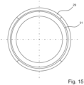
- the figures 14 and 15 show a side view of the in the figures 11 and 12 shown divisible cuff 29 and the welded-on cuff 29.
- Both butt and overlap welds can be produced with electron beam and laser welding.
Landscapes
- Engineering & Computer Science (AREA)
- Mechanical Engineering (AREA)
- Physics & Mathematics (AREA)
- Optics & Photonics (AREA)
- Plasma & Fusion (AREA)
- Welding Or Cutting Using Electron Beams (AREA)
Applications Claiming Priority (1)
| Application Number | Priority Date | Filing Date | Title |
|---|---|---|---|
| DE102021129395.2A DE102021129395A1 (de) | 2021-11-11 | 2021-11-11 | Vorrichtung und Verfahren zum Elektronenstrahlschweißen und Laserstrahlschweißen von dickwandigen Rohren und Druckbehältern |
Publications (3)
| Publication Number | Publication Date |
|---|---|
| EP4190476A1 true EP4190476A1 (fr) | 2023-06-07 |
| EP4190476C0 EP4190476C0 (fr) | 2026-02-18 |
| EP4190476B1 EP4190476B1 (fr) | 2026-02-18 |
Family
ID=84331478
Family Applications (1)
| Application Number | Title | Priority Date | Filing Date |
|---|---|---|---|
| EP22206795.1A Active EP4190476B1 (fr) | 2021-11-11 | 2022-11-10 | Dispositif et procédé de soudage par faisceau laser de tubes à paroi épaisse et de récipients sous pression |
Country Status (2)
| Country | Link |
|---|---|
| EP (1) | EP4190476B1 (fr) |
| DE (1) | DE102021129395A1 (fr) |
Cited By (1)
| Publication number | Priority date | Publication date | Assignee | Title |
|---|---|---|---|---|
| CN117359074A (zh) * | 2023-10-27 | 2024-01-09 | 洛阳船舶材料研究所(中国船舶集团有限公司第七二五研究所) | 一种大尺寸环形金属管局部真空电子束焊接系统 |
Families Citing this family (1)
| Publication number | Priority date | Publication date | Assignee | Title |
|---|---|---|---|---|
| CN119457445B (zh) * | 2025-01-13 | 2025-05-23 | 河北众航高能科技有限公司 | 一种低真空激光与高真空电子束焊接的双源复合焊接设备 |
Citations (7)
| Publication number | Priority date | Publication date | Assignee | Title |
|---|---|---|---|---|
| DE2632252A1 (de) | 1976-07-17 | 1978-01-19 | Thyssen Industrie | Vorrichtung zum herstellen von rohren o.dgl. durch verschweissen von einzelschuessen mittels des elektronenstrahlschweissverfahrens und mit dieser vorrichtung hergestelltes rohr |
| AU500409B2 (en) * | 1975-06-30 | 1979-05-24 | A. T Gowing | Alignment device |
| FR2467657A1 (fr) * | 1979-10-17 | 1981-04-30 | Thome Paul | Dispositif d'etancheite et d'alignement pour soudage de canalisations par faisceau d'electrons sous vide |
| FR2519280A1 (fr) * | 1982-01-06 | 1983-07-08 | Petroles Cie Francaise | Machine pour le soudage bout a bout de deux tubes par fa isceau d'electrons et procedure de mise en place de cette machine |
| US4638142A (en) * | 1984-10-22 | 1987-01-20 | Total Compagnie Francaise Des Petroles | Machine for electron-beam internal butt welding of tubes |
| DE19527048A1 (de) | 1995-07-25 | 1997-01-30 | Fraunhofer Ges Forschung | Einrichtung zur Durchführung elektronenstrahltechnologischer Prozesse |
| DE102009041383A1 (de) | 2009-09-12 | 2011-03-24 | Ruchay, Wilfried, Dipl.-Ing. | Verfahren und Anordnung zum Verbinden von offenen Hohlkörpern durch Elektronenstrahlschweißen |
Family Cites Families (1)
| Publication number | Priority date | Publication date | Assignee | Title |
|---|---|---|---|---|
| GB201609995D0 (en) * | 2016-06-08 | 2016-07-20 | Aquasium Technology Ltd | Shaped welding head |
-
2021
- 2021-11-11 DE DE102021129395.2A patent/DE102021129395A1/de active Pending
-
2022
- 2022-11-10 EP EP22206795.1A patent/EP4190476B1/fr active Active
Patent Citations (7)
| Publication number | Priority date | Publication date | Assignee | Title |
|---|---|---|---|---|
| AU500409B2 (en) * | 1975-06-30 | 1979-05-24 | A. T Gowing | Alignment device |
| DE2632252A1 (de) | 1976-07-17 | 1978-01-19 | Thyssen Industrie | Vorrichtung zum herstellen von rohren o.dgl. durch verschweissen von einzelschuessen mittels des elektronenstrahlschweissverfahrens und mit dieser vorrichtung hergestelltes rohr |
| FR2467657A1 (fr) * | 1979-10-17 | 1981-04-30 | Thome Paul | Dispositif d'etancheite et d'alignement pour soudage de canalisations par faisceau d'electrons sous vide |
| FR2519280A1 (fr) * | 1982-01-06 | 1983-07-08 | Petroles Cie Francaise | Machine pour le soudage bout a bout de deux tubes par fa isceau d'electrons et procedure de mise en place de cette machine |
| US4638142A (en) * | 1984-10-22 | 1987-01-20 | Total Compagnie Francaise Des Petroles | Machine for electron-beam internal butt welding of tubes |
| DE19527048A1 (de) | 1995-07-25 | 1997-01-30 | Fraunhofer Ges Forschung | Einrichtung zur Durchführung elektronenstrahltechnologischer Prozesse |
| DE102009041383A1 (de) | 2009-09-12 | 2011-03-24 | Ruchay, Wilfried, Dipl.-Ing. | Verfahren und Anordnung zum Verbinden von offenen Hohlkörpern durch Elektronenstrahlschweißen |
Cited By (1)
| Publication number | Priority date | Publication date | Assignee | Title |
|---|---|---|---|---|
| CN117359074A (zh) * | 2023-10-27 | 2024-01-09 | 洛阳船舶材料研究所(中国船舶集团有限公司第七二五研究所) | 一种大尺寸环形金属管局部真空电子束焊接系统 |
Also Published As
| Publication number | Publication date |
|---|---|
| EP4190476C0 (fr) | 2026-02-18 |
| DE102021129395A1 (de) | 2023-05-11 |
| EP4190476B1 (fr) | 2026-02-18 |
Similar Documents
| Publication | Publication Date | Title |
|---|---|---|
| DE2559532C3 (de) | Vorrichtung zum Ausrichten und Festlegen des Endes einer Rohrleitung und eines damit zu verschweißenden Rohrstückes | |
| EP2928636B1 (fr) | Dispositif destiné au serrage et à l'alignement de pièces profilées creuses, à parois minces et sous forme de segments, et son utilisation | |
| EP3046722B1 (fr) | Gabarit de soudage équipé d'un dispositif chauffant ayant pour effet de chauffer la pièce | |
| DE68904049T2 (de) | Schweissverfahren und schweissvorrichtung, um aus der entfernung eine muffe in ein rohr, insbesondere innerhalb eines dampferzeugers eines kernkraftwerkes, einzuschweissen. | |
| EP4190476B1 (fr) | Dispositif et procédé de soudage par faisceau laser de tubes à paroi épaisse et de récipients sous pression | |
| DE69101935T2 (de) | Elastische Schelle zum Ausrichten. | |
| DE3604677C2 (fr) | ||
| EP3600694B1 (fr) | Procédé de revêtement de tuyaux et installation de revêtement | |
| EP2121285B1 (fr) | Procédé de soudage au laser | |
| DE3015905C2 (fr) | ||
| WO2021180355A1 (fr) | Procédé de production de joints soudés entre des tubes internes et des plaques porte-tube d'un faisceau tubulaire pour un échangeur de chaleur à faisceau tubulaire de type produit à produit au moyen d'un dispositif auxiliaire, et dispositif auxiliaire conçu pour un tel procédé de production | |
| EP4313471A2 (fr) | Dispositif et procédé de soudage | |
| WO2014202058A1 (fr) | Dispositif et procédé de fabrication de tubes à vide | |
| DE2250936C2 (de) | Vorrichtung zum aufeinanderfolgenden Schweißen von Werkstücken mittels Elektronenstrahlen | |
| DE10036746B4 (de) | Absorberrohr insbesondere für Parabolrinnenkollektoren in solarthermischen Kraftwerken | |
| WO2008113369A1 (fr) | Procédé de production d'une paroi de membrane | |
| EP0489192A1 (fr) | Condenseur refroidi par eau | |
| DE2632252A1 (de) | Vorrichtung zum herstellen von rohren o.dgl. durch verschweissen von einzelschuessen mittels des elektronenstrahlschweissverfahrens und mit dieser vorrichtung hergestelltes rohr | |
| WO2011085876A1 (fr) | Dispositif d'étanchéité permettant de former une chambre à gaz de protection | |
| DE102008027322A1 (de) | Druckstufensystem für eine Vorrichtung zum Elektronenstrahlschweißen und Verfahren zum Elektronenstrahlschweißen | |
| DE102016000880B3 (de) | Vorrichtung und Verfahren zum rückstandsfreien Rührreibverschweißen von Werkstücken, insbesondere von rohrartigen Strukturen, sowie Computerprogramm zur Durchführung der Verfahrensschritte | |
| DE3116123A1 (de) | "elektronenstrahl-schweisskammer zum stumpfstoss laenglicher bauteile" | |
| DE102009041826A1 (de) | System zum Schweißen von Metallen | |
| EP3022006B1 (fr) | Sonotrode, procédé de fabrication de soudures par ultrasons utilisant une telle sonotrode, dispositif de soudage pour mise en oeuvre du procédé comprenant une telle sonotrode | |
| DE3537558A1 (de) | Maschine zur stumpfschweissung von rohren mittels von aussen kommendem elektronenstrahl |
Legal Events
| Date | Code | Title | Description |
|---|---|---|---|
| PUAI | Public reference made under article 153(3) epc to a published international application that has entered the european phase |
Free format text: ORIGINAL CODE: 0009012 |
|
| STAA | Information on the status of an ep patent application or granted ep patent |
Free format text: STATUS: THE APPLICATION HAS BEEN PUBLISHED |
|
| AK | Designated contracting states |
Kind code of ref document: A1 Designated state(s): AL AT BE BG CH CY CZ DE DK EE ES FI FR GB GR HR HU IE IS IT LI LT LU LV MC ME MK MT NL NO PL PT RO RS SE SI SK SM TR |
|
| STAA | Information on the status of an ep patent application or granted ep patent |
Free format text: STATUS: REQUEST FOR EXAMINATION WAS MADE |
|
| 17P | Request for examination filed |
Effective date: 20231206 |
|
| RBV | Designated contracting states (corrected) |
Designated state(s): AL AT BE BG CH CY CZ DE DK EE ES FI FR GB GR HR HU IE IS IT LI LT LU LV MC ME MK MT NL NO PL PT RO RS SE SI SK SM TR |
|
| STAA | Information on the status of an ep patent application or granted ep patent |
Free format text: STATUS: EXAMINATION IS IN PROGRESS |
|
| 17Q | First examination report despatched |
Effective date: 20241210 |
|
| GRAP | Despatch of communication of intention to grant a patent |
Free format text: ORIGINAL CODE: EPIDOSNIGR1 |
|
| STAA | Information on the status of an ep patent application or granted ep patent |
Free format text: STATUS: GRANT OF PATENT IS INTENDED |
|
| INTG | Intention to grant announced |
Effective date: 20250916 |
|
| GRAS | Grant fee paid |
Free format text: ORIGINAL CODE: EPIDOSNIGR3 |
|
| GRAA | (expected) grant |
Free format text: ORIGINAL CODE: 0009210 |
|
| STAA | Information on the status of an ep patent application or granted ep patent |
Free format text: STATUS: THE PATENT HAS BEEN GRANTED |
|
| AK | Designated contracting states |
Kind code of ref document: B1 Designated state(s): AL AT BE BG CH CY CZ DE DK EE ES FI FR GB GR HR HU IE IS IT LI LT LU LV MC ME MK MT NL NO PL PT RO RS SE SI SK SM TR |
|
| REG | Reference to a national code |
Ref country code: CH Ref legal event code: F10 Free format text: ST27 STATUS EVENT CODE: U-0-0-F10-F00 (AS PROVIDED BY THE NATIONAL OFFICE) Effective date: 20260218 Ref country code: GB Ref legal event code: FG4D Free format text: NOT ENGLISH |
|
| REG | Reference to a national code |
Ref country code: DE Ref legal event code: R096 Ref document number: 502022007081 Country of ref document: DE |
|
| REG | Reference to a national code |
Ref country code: IE Ref legal event code: FG4D Free format text: LANGUAGE OF EP DOCUMENT: GERMAN |
|
| U01 | Request for unitary effect filed |
Effective date: 20260305 |
|
| U07 | Unitary effect registered |
Designated state(s): AT BE BG DE DK EE FI FR IT LT LU LV MT NL PT RO SE SI Effective date: 20260313 |
|
| PG25 | Lapsed in a contracting state [announced via postgrant information from national office to epo] |
Ref country code: RS Free format text: LAPSE BECAUSE OF FAILURE TO SUBMIT A TRANSLATION OF THE DESCRIPTION OR TO PAY THE FEE WITHIN THE PRESCRIBED TIME-LIMIT Effective date: 20260518 |
|
| PG25 | Lapsed in a contracting state [announced via postgrant information from national office to epo] |
Ref country code: ES Free format text: LAPSE BECAUSE OF FAILURE TO SUBMIT A TRANSLATION OF THE DESCRIPTION OR TO PAY THE FEE WITHIN THE PRESCRIBED TIME-LIMIT Effective date: 20260218 |
|
| PG25 | Lapsed in a contracting state [announced via postgrant information from national office to epo] |
Ref country code: PL Free format text: LAPSE BECAUSE OF FAILURE TO SUBMIT A TRANSLATION OF THE DESCRIPTION OR TO PAY THE FEE WITHIN THE PRESCRIBED TIME-LIMIT Effective date: 20260218 |
|
| PG25 | Lapsed in a contracting state [announced via postgrant information from national office to epo] |
Ref country code: GR Free format text: LAPSE BECAUSE OF FAILURE TO SUBMIT A TRANSLATION OF THE DESCRIPTION OR TO PAY THE FEE WITHIN THE PRESCRIBED TIME-LIMIT Effective date: 20260519 |
|
| PG25 | Lapsed in a contracting state [announced via postgrant information from national office to epo] |
Ref country code: NO Free format text: LAPSE BECAUSE OF FAILURE TO SUBMIT A TRANSLATION OF THE DESCRIPTION OR TO PAY THE FEE WITHIN THE PRESCRIBED TIME-LIMIT Effective date: 20260518 |
|
| PG25 | Lapsed in a contracting state [announced via postgrant information from national office to epo] |
Ref country code: HR Free format text: LAPSE BECAUSE OF FAILURE TO SUBMIT A TRANSLATION OF THE DESCRIPTION OR TO PAY THE FEE WITHIN THE PRESCRIBED TIME-LIMIT Effective date: 20260218 |
|
| PG25 | Lapsed in a contracting state [announced via postgrant information from national office to epo] |
Ref country code: IS Free format text: LAPSE BECAUSE OF FAILURE TO SUBMIT A TRANSLATION OF THE DESCRIPTION OR TO PAY THE FEE WITHIN THE PRESCRIBED TIME-LIMIT Effective date: 20260618 |