EP4190489A1 - System und verfahren zum blockieren einer ophthalmischen linse mit einem einsatz - Google Patents
System und verfahren zum blockieren einer ophthalmischen linse mit einem einsatz Download PDFInfo
- Publication number
- EP4190489A1 EP4190489A1 EP21306673.1A EP21306673A EP4190489A1 EP 4190489 A1 EP4190489 A1 EP 4190489A1 EP 21306673 A EP21306673 A EP 21306673A EP 4190489 A1 EP4190489 A1 EP 4190489A1
- Authority
- EP
- European Patent Office
- Prior art keywords
- glue
- ophthalmic lens
- chamber
- gas
- insert
- Prior art date
- Legal status (The legal status is an assumption and is not a legal conclusion. Google has not performed a legal analysis and makes no representation as to the accuracy of the status listed.)
- Pending
Links
Images
Classifications
-
- B—PERFORMING OPERATIONS; TRANSPORTING
- B24—GRINDING; POLISHING
- B24B—MACHINES, DEVICES, OR PROCESSES FOR GRINDING OR POLISHING; DRESSING OR CONDITIONING OF ABRADING SURFACES; FEEDING OF GRINDING, POLISHING, OR LAPPING AGENTS
- B24B13/00—Machines or devices designed for grinding or polishing optical surfaces on lenses or surfaces of similar shape on other work; Accessories therefor
- B24B13/005—Blocking means, chucks or the like; Alignment devices
Definitions
- the invention relates to a system and method for blocking an ophthalmic lens with an insert.
- It also relates to an optical article comprising an ophthalmic lens and an insert bonded by a glue.
- the opposite optical surface Prior to surfacing an optical surface of an ophthalmic lens according to a given prescription, the opposite optical surface is blocked onto an insert.
- the ophthalmic lens is maintained by this insert during the surfacing process.
- the ophthalmic lens and the insert are structurally bonded by a glue which is classically polymerized by exposure to ultraviolet light. After the surfacing process, the glue is removed during a deblocking step.
- these steps comprise wiping, brushing, or cleaning the glue with chemical containing solvents or caustic materials, sometimes used at high temperature (around 60°C), and/or using ultrasound cavitation.
- the invention proposes a system for blocking an ophthalmic lens with an insert, said system comprising:
- the polymerization of the glue is carried under a strict control of the oxygen concentration of the gas surrounding the glue.
- the oxygen concentration is controlled such that the polymerization of the glue is not inhibited by oxygen, which allows a complete polymerization of the glue.
- the invention also relates to a method for blocking an ophthalmic lens with an insert comprising the steps of:
- the invention also relates to an optical article, produced by the system and method, comprising:
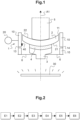
- Figure 1 shows a system 1 for blocking an ophthalmic lens 2 with an insert 3 according to the invention.
- the system 1 is also called a "blocker”.
- the system 1 comprises:
- the system 1 also comprises a blocking head 5 adapted to hold the ophthalmic lens 2.
- the blocking head 5 for example comprises means, such as a suction cup, for removably maintaining the ophthalmic lens 2.
- the ophthalmic lens 2 might also be stuck to the blocking head 5.
- the blocking head 5 is for example provided at one end of a robotic arm designed to move the ophthalmic lens 2.
- the ophthalmic lens 2 is a semi-finished lens in the sense that it comes from an injection molding step or a casting step and it still has to undergo at least one surfacing step.
- the ophthalmic lens 2 is globally disk-shaped.
- the ophthalmic lens 2 has two circular optical surfaces linked by a peripheral edge.
- the semi-finished ophthalmic lens 2 has a diameter which is typically comprised between 76 mm and 81 mm.
- the ophthalmic lens 2 is for example molded such as to provide a standard spherical power (for instance 1 or 2 diopters).
- the ophthalmic lens 2 thus has a first optical surface 21 which is convex.
- the ophthalmic lens 2 is bonded to the insert 3 by the first optical surface 21.
- the first ophthalmic surface might be flat.
- the ophthalmic lens 2 and the insert 3 being "bonded” means that they are firmly attached or fixed to each other. More specifically, it means that ophthalmic lens 2 and the insert 3 are stuck to each other by the glue 4.
- the term “blocking” refers to the action of bonding the ophthalmic lens 2 on the insert 3.
- the glue 4 is designed to polymerize under exposure to ultraviolet light, hereafter referred to as UV light.
- the glue 4 comprises polymers which are commonly referred to as "UV glues". UV light is required to trigger a radical polymerization of the glue 4.
- the glue 4 for example comprises an epoxy resin or a resin combining acrylate and methacrylate, in which photoinitiators are dispersed.
- the polymerization of the glue 4, also called curing of the glue 4, corresponds to the hardening or solidification of the glue 4.
- the glue 4 is viscous and can be deposited on the insert 3 or on the ophthalmic lens 2. While the glue 4 is polymerizing, the glue 4 becomes solid and starts binding the insert 3 and the ophthalmic lens 2 together. At the end of the polymerization, the glue 4 bonds the insert 3 and the ophthalmic lens 2.
- the insert 3 allows holding the ophthalmic lens 2 during the surfacing step, here the surfacing of a second optical surface 22 opposite to the first optical surface 21.
- the second optical surface 22 is concave.
- the insert 3 can be attached in a removable manner to a rotational axis and for example comprises means for engaging with the rotational axis.
- the insert 3 may also be used to hold the ophthalmic lens 2 during a trimming step of its peripheral edge. As shown in figure 1 , the insert 3 is less large than the ophthalmic lens 2.
- the glue 4 adheres to both the insert 3 and the ophthalmic lens 2 strongly enough to withstand mechanical stresses induced by the surfacing step.
- the ophthalmic lens 2 and the insert 3 being "bonded” therefore more specifically means that they are sufficiently attached to each other to withstand these mechanical stresses.
- the chamber formed in the cover 10 is adapted to be filled with the gas and, simultaneously, to contain the ophthalmic lens 2 and the insert 3 when they are being bonded by the glue 4.
- the cover 10 is a hollow element in the sense that the cover 10 comprises a hole or a cavity extending through the cover 10.
- the cover 10 thus has, on the inside, an inner surface 11 which delimits the chamber.
- the cover 10 is more particularly a hollow cylinder wherein the inner surface 11 extends along a circular cylindrical surface centered on a longitudinal axis A1 (which is vertical in figure 1 ).
- the cover 10 comprises, at a first extremity of the hollow cylinder, an upper opening, hereafter referred to as "the opening", and, at the other extremity of the hollow cylinder, a lower opening.
- the lower opening is closed by a support 6 onto which lays the cover 10.
- the support 6 is substantially plan, orthogonal to the longitudinal axis A1, and comprises a hole in which the insert 3 is positioned.
- the hole and the insert are also centered around the longitudinal axis A1.
- the cover 10 may be fixed to the support 6, preferably in a removable manner, for example by means of screws. In this way, the cover 10 can then be taken out of the system 1, for example for maintenance.
- the cover is a cup-shaped element comprising a recess which forms the chamber.
- the cover comprises, in addition to the cylindrical inner surface, a circular bottom face facing the opening and sealing the bottom of the chamber.
- the bottom face may also comprise a hole to position the insert.
- the cover 10 is here made of a monobloc piece of metallic material.
- the cover 10 is preferentially made of stainless steel to increase its durability.
- the cover can be made of a plastic material.
- the cover is preferentially made of a material which is not sensitive to photodegradation such as acrylic or polycarbonate.
- the cover could also be 3D printed.
- the chamber is an available space, in the sense that it is not filled by the cover 10, extending from the opening to the support 6.
- the insert 3 is positioned in the chamber, here against the support 6 as represented in figure 1 , and the glue 4 lies on the insert 3.
- the chamber is larger than the insert 3 but the insert 3 may have a width close to the diameter of the chamber. This limits the internal volume of the chamber and therefore limits the volume of the gas for which the oxygen concentration is controlled.
- the cover and the chamber may have any other shape adapted for placing the insert 3, the ophthalmic lens 2 and the glue 4.
- the chamber may have the shape of a parallelepiped.
- the chamber is at least partly sealed, i.e. sealed or partly sealed, while the glue 4 is polymerizing.
- the chamber being “sealed” means that the opening of the cover 10 is closed.
- the chamber being “partly sealed” means that inputs or outputs of gas into or from the chamber are limited, for instance small or negligible leaks of the gas may be tolerated, in such a way that the oxygen concentration is still controlled.
- "sealed” may mean that the chamber is totally hermetic.
- the gas refers to the gas present in the chamber during the polymerization of the glue 4, that is to say the gas surrounding the glue 4 while it is polymerizing.
- the diameter of the opening is substantially equal to the diameter of the ophthalmic lens 2.
- substantially equal means that the diameter of the ophthalmic lens 2 is slightly smaller than the diameter of the opening such that the ophthalmic lens 2 interlocks in the opening tightly enough to seal the chamber.
- the diameter of the opening is preferentially 0.1 mm to 5.0 mm larger than the diameter of the ophthalmic lens 2.
- the diameter of the opening is 0.1 mm larger than the diameter of the ophthalmic lens 2, it is considered that the chamber is sealed by the ophthalmic lens 2.
- the diameter of the opening is 5 mm larger than the diameter of the ophthalmic lens 2, it is considered that the chamber is partly sealed by the ophthalmic lens 2.
- Figure 1 illustrates an embodiment wherein the diameter of the ophthalmic lens 2 is for example equal 81 mm and the diameter of the opening is for example equal to 85 mm such as to partly seal the chamber.
- the cover 10 is designed, based on the ophthalmic lens 2 and the insert 3, in order to minimize the internal volume of the chamber.
- the ophthalmic lens may be larger than the opening but seal the chamber nevertheless by covering the opening.
- the first optical surface is for example a regular convex surface having a symmetry of revolution.
- the chamber may be sealed by an additional cap or may be put under a bell.
- the cover 10 comprises an inlet 13 adapted to bring a prime gas into the chamber.
- the prime gas can be flushed into the chamber through the inlet 13.
- the inlet 13 is hole, for example circular, made in the cover 10 and leading the inner surface 11.
- the inlet 13 may for example also extend through the support 6.
- the inlet 13 may be formed in this additional cap.
- the inlet 13 is for example connected through a pipe to a tank filled with the prime gas.
- the prime gas is for example under pressure inside the tank and may be injected in the chamber through the inlet 13 by controlling a valve located between the tank and the inlet 13.
- the oxygen concentration of the prime gas is predetermined. As explained later on, this allows controlling the oxygen concentration of the gas inside the chamber.
- the prime gas is for example an oxygen free air.
- the prime gas is preferentially an inert gas such as nitrogen, argon, carbon dioxide or a mix thereof.
- the prime gas is preferentially a heavy gas. More specifically, the prime gas preferentially has a density higher than the density of air.
- the heavy prime gas stays inside the chamber even though the chamber is only partially sealed (since the opening is at the top of the chamber). When flushed into the chamber, the gas for example allows creating an inert atmosphere.
- the inlet 13 is facing the glue 4 in the sense that it is positioned at the same height, along the longitudinal axis A1, as the glue 4.
- the inlet 13 is positioned at a height comprised between 0.0 mm to 0.5 mm above the highest point of the insert 3 along the longitudinal axis A1, i.e. in the direction of the ophthalmic lens 2.
- the prime gas flows directly onto the periphery of the glue 4, that is to say an area of the glue 4 which needs protection from oxygen.
- the cover 10 also comprises an outlet 14 adapted to let the gas exit the chamber.
- the outlet 14 is an exhaust for the gas in the chamber.
- the outlet 14 is for example a hole which may be terminated by a controllable valve.
- the outlet 14 is also provided in the cover 10 on its inner surface 11.
- the outlet 14 could also be provided on the support 6 or on the additional cap.
- the cover does not comprise an outlet, for instance when the chamber is only partially sealed during the polymerization of the glue 4.
- the outlet 14 may be connected to a pumping system in order to reach a vacuum atmosphere (so without oxygen) in the chamber.
- the outlet 14 and the inlet 13 are comprised in a plane substantially parallel to a mean plane of the ophthalmic lens 2.
- the mean plane of the ophthalmic lens 2 is for example the plan which best fits one of the optical surfaces.
- the mean plane of ophthalmic lens 2 is for instance parallel to the support 6.
- the outlet 14 and the inlet 13 are positioned at the same height in the chamber, for example with respect to the support 6. In this way, a flow of the gas from the inlet 13 to the outlet 14 circulates homogeneously around the glue 4.
- the distance between the outlet 14 and the inlet 13 is small, for example comprised between 1 cm and 5 cm.
- the system 1 comprises a lamp 30 designed to emit UV light for polymerizing the glue 4.
- the lamp 30 for example comprises one or more LEDs.
- the lamp 30 is here located below the cover 10 (that is to say, opposite to the blocking head 5), for example under the support 6, and oriented toward the chamber.
- UV light goes into the chamber through the insert 3 which is made transparent to UV light.
- the insert 3 is for example made of acrylic.
- the support 6 may also be transparent such that UV light can also reach the chamber through the support 6.
- the lamp may also be the support itself.
- the hollow shape of the cover 10 therefore allows the ophthalmic lens 2 to enter the chamber from one side and UV light from the other side.
- An additional lamp may be positioned inside the chamber, preferentially circumferentially all around the glue 4.
- the additional lamp may be turned on and off at the same time as the lamp 30.
- the additional lamp improves the polymerization of the periphery of the glue 4.
- the lamp may be positioned inside the chamber.
- the cover 10 comprises an inner layer reflecting UV light.
- the inner layer reflecting UV light is made of the inner surface 11 itself since the cover 10 is metallic.
- the inner layer may also be a thin metallic film deposited or coated on the inner surface 11.
- the inner layer allows deflecting more UV light toward the glue 4, which, in turns, accelerates and homogenizes the polymerization of the glue 4.
- the control unit 20 for example comprises one or more memories and one or more processors.
- the one or more memories have in memory instructions which, when implemented by the one or more processors, allow controlling the oxygen concentration of the gas while the glue 4 is polymerizing.
- the control unit 20 is programmed to control the oxygen concentration of the gas while the glue 4 is polymerizing.
- the control unit 20 is connected to the inlet 13 and the tank such that the control unit 20 can control the injection of the prime gas into the chamber.
- the control unit 20 controls the extent of the opening of the valve between the tank and the inlet 13.
- the control unit 20 may be connected to a pump adapted to pump the prime gas from the tank into the chamber.
- the control unit 20 is also connected to the lamp 30 such that the control unit 20 can control the lighting of the lamp 30, i.e. turning the lamp 30 on and off.
- the control unit 20 is also connected to an oxygen monitor 40 adapted to measure the oxygen concentration of the gas inside the chamber.
- the oxygen monitor 40 for example comprises a probe, a sensor or any other device adapted to detect oxygen.
- the control unit 20 can also be adapted to position the blocking head 5, and therefore to position the ophthalmic lens 2, for instance by controlling the robotic arm.
- the blocking head might be controlled by an independent and dedicated control unit.
- control unit 20 controls the oxygen concentration of the gas inside the chamber while the glue 4 is polymerizing such that the polymerization of the glue 4 is not inhibited by oxygen.
- the edges of the glue 4 (which are neither in contact with the ophthalmic lens 2 nor the insert 3) are not in contact with oxygen or are in contact with so little oxygen that the polymerization is not hindered. No area of the glue 4 remains underpolymerized and sticky. The further removal and cleaning of the glue 4 is therefore facilitated.
- controlling the oxygen concentration of the gas means maintaining the oxygen concentration of the gas below a predetermined concentration while the glue 4 is polymerizing.
- the predetermined oxygen concentration is a value which may be expressed in several units.
- the predetermined concentration value is for example comprised between 1 ppm (parts per million) and 10000 ppm or between 0.0001 % and 1 % of the mass or volume of the gas, preferably between 100 pm and 1000 pm or between 0.01 % and 0.1 % of the mass or volume of the gas.
- the predetermined concentration may be chosen based on the duration of the polymerization. Typically, the longer the duration of the polymerization is, the lower the predetermined concentration is. The duration of the polymerization depends on the composition of the glue 4 and the intensity of UV light.
- control units 20 may monitor the oxygen concentration by means of the oxygen monitor 40. Then, the control unit 20 controls the injection of the prime gas into the chamber until the oxygen concentration of the gas decreases below the predetermined concentration.
- this allows to inject only the needed amount of the prime gas and therefore to save the latest.
- the gas inside the chamber when the glue 4 is polymerizing may then be a mix between air previously present inside the chamber and the prime gas injected through the inlet 13.
- controlling the oxygen concentration of the gas means completely filling the chamber with the prime gas.
- the prime gas completely replaces the air previously present inside the chamber.
- the gas inside the chamber while the glue 4 is polymerizing is the same as the prime gas. Since the oxygen concentration of the prime gas is predetermined, the oxygen concentration of the gas inside the chamber is controlled. The oxygen concentration of the gas is then more specifically equal to the oxygen concentration of the prime gas.
- the prime gas being preferentially an inert gas free of oxygen, the oxygen concentration of the gas inside the chamber is then close to zero, for example between 0.1 ppm to 30 ppm.
- controlling the oxygen concentration may then mean flushing continuously the prime gas into the chamber while the glue 4 is polymerizing. It may also mean vacuuming the chamber, for example thanks to a pump connected to the outlet 14, before filling the chamber with the prime gas and sealing it for the polymerization of the glue 4. It may also mean flushing the prime gas into the chamber, with the outlet 14 open, for a predetermined time period before sealing the chamber.
- controlling the oxygen concentration means maintaining an atmosphere free of oxygen in the chamber during the polymerization of the glue 4.
- This oxygen free atmosphere is for example achieved by using an inert gas as the prime gas (for instance argon) and by filling the chamber with the prime gas as explained in the second example.
- controlling the oxygen concentration means reaching a vacuum atmosphere in the chamber.
- the vacuum atmosphere may be reached thanks to the pumping system connected to the outlet 14.
- the whole cover 10 may also be put under a vacuum bell.
- the control unit 20 might be connected to a vacuum gauge adapted to measure the pressure inside the vacuum bell.
- controlling the oxygen concentration means capturing the oxygen present inside the chamber in order to reduce the oxygen concentration.
- the system 1 may comprise an oxygen filter, for example located at the outlet 14.
- the control unit 20 is also adapted to control the emission of UV light, that is to say the lighting of the lamp 30, when the oxygen concentration is being controlled.
- the control unit 20 may trigger the lighting of the lamp 30 when the oxygen concentration has fallen below the predetermined oxygen concentration or after a given time period, for example 30 seconds of continuously flowing the primer gas into the chamber.
- the lamp may be controlled independently from the control unit, for example by a manual switch.
- the control unit 20 is also adapted to control the pressure inside the chamber. In a remarkable manner, building a moderate overpressure inside the chamber ensures that potential leaks (for instance when the chamber is partially sealed) are oriented from the chamber to the exterior of the chamber and not the other way around. Oxygen can therefore not penetrate the chamber in an uncontrolled manner while the glue 4 is polymerizing.
- the pressure in the chamber may be regulated by controlling the flow of the prime gas through the inlet 13 and/or the exit flow of the gas through the outlet 14.
- the system 1 may comprise a sensor adapted to measure the pressure in the chamber which is located in the chamber and connected to the control unit 20.
- the control unit 20 here comprises a safety procedure wherein the outlet 14 can be largely opened to avoid dangerous overpressures.
- control unit 20 is also adapted to control the oxygen concentration of the gas in the chamber while the glue 4 is being deposited inside the chamber.
- the oxygen concentration may be controlled while the glue 4 is being deposited on the insert 3.
- the prime gas may have a density greater than the density of air and be steadily injected into the chamber. The prime gas thus naturally rests in the chamber (since the opening is at the top of the cover 10) and, in particular, around the insert 3 and the glue 4.
- the system 1 allows to implement a method for blocking the ophthalmic lens 2 with the insert 3.
- the method comprises the following main steps:
- the method starts with a step E1 of placing the insert 13 in the chamber.
- the insert 3 is placed in the hole provided in the support 6.
- the insert 3 is located at distance from the inner surface 11 and centered with respect to the chamber.
- step E2 the glue 4 is deposited on the insert 3, here on a surface of the insert 3 opposite to the support 6.
- the glue 4 may be deposited on a central region of this surface but could also be spread on all this surface.
- step E2 the polymerization of the glue 4 has not started yet and the glue 4 is fluid or viscous.
- the system 1 may comprise a dedicated conduit or syringe to deposit the glue 4.
- step E3 wherein the ophthalmic lens 2 is positioned at the opening such as to seal or partly seal the chamber but without touching the glue 4.
- the ophthalmic lens 2 is centered with respect to the chamber, that is to say around the longitudinal axis A1, and brought to the opening of the cover 10 in order to interlock with the opening.
- step E3 is carried out by means of the robotic arm to which the blocking head 5 is fixed.
- the ophthalmic lens 2 is for example held between 1 cm and 2 cm above the insert 3.
- step E4 wherein the control units 20 starts controlling the oxygen concentration of the gas in the chamber.
- step E4 may comprise maintaining the oxygen concentration of the gas below the predetermined concentration. Controlling the oxygen concentration before the ophthalmic lens 2 touches the glue 4 reduces the probability that underpolymerized portions of glue 4 remains on the first optical surface 21 since the first optical surface 21 is not contaminated with oxygen when touching the glue 4.
- Step E5 the ophthalmic lens 2 is brought in contact with the glue 4.
- Step E5 is for example triggered when the oxygen concentration is being controlled, for example when it drops below the predetermined concentration.
- the ophthalmic lens 2 is preferentially held parallel to the support 6 (and therefore parallel to the layer made by the glue 4). This prevents, thanks to the convex shape of the first optical surface 21, trapping air bubbles between the glue 4 and the ophthalmic lens 2.
- step E5 is also carried out by means of the robotic arm to which the blocking head 5 is attached. Bringing the ophthalmic lens 2 in contact with the glue 4 may also participate in spreading the glue 4 on surface of the insert 3 opposite to the support 6, in particular when the glue 4 is deposited only on the central region of this surface.
- the polymerization of the glue 4 can be started and carried out in order for the glue 4 to bond the insert 3 and the ophthalmic lens 2 together.
- step E6 which comprises the emission of UV light by the lamp 30.
- step E6 the lamp 30 is turned on and the glue 4 polymerizes under exposition to UV light.
- step E4 is performed all along step E6.
- Step E6 for example lasts between 1 second and 10 seconds.
- the duration of step E6 depends on the intensity of the UV light, the composition of the glue 4 and the quantity of the glue 4 deposited.
- step E6 is preferentially performed until the glue 4 is completely polymerized, i.e. until no portion of the glue 4 remains sticky.
- Step E6 may also be performed until a predetermined level of polymerization is reached. This predetermined level may be determined empirically thanks to a dedicated series of tests. The level of polymerization of the glue may be evaluated by differential scanning calorimetry measurements or by measurements of the tackiness of the glue 4. For instance, step E6 may be performed until a predetermined percent of the volume or of the mass of the glue 4 is polymerized, for example 90%.
- step E6 the lamp 30 is turned off.
- Controlling the oxygen concentration during the polymerization of the glue 4 is the main way to prevent an incomplete polymerization due to oxygen inhibition.
- oxygen concentration may also be controlled when the glue 4 is being deposited. The oxygen concentration is then controlled until the end of the polymerization.
- the prime gas is preferentially a heavy gas such as argon.
- the glue 4 may be stored in an environment where the oxygen concentration is also controlled.
- the oxygen concentration may be controlled only after the ophthalmic lens is brought in contact with the glue.
- the control unit may light the lamp only when the oxygen concentration drops below the predetermined concentration.
- the lamp emits light only when the oxygen concentration of the gas is being controlled.
- the method according to the invention may be automated in the sense that no manual intervention on the system 1, such as manually handling the insert 3 or the ophthalmic lens 2, is required.
- the ophthalmic lens 2 may for example be handled by the robotic arm.
- the insert 3 may also be handled by robotic prehension tools.
- placing the ophthalmic lens 2, the insert 3 and the glue 4 in the chamber may be performed in a plurality of ways and orders.
- the ophthalmic lens 2 may be firstly deposited on the support 6, then the glue 4 may be deposited on the ophthalmic lens 2 and finally the insert 3 positioned in contact with the glue 4.
- an additional cap may be used to seal the cover 10.
- the glue 4 may be inserted between the ophthalmic 2 and the insert 3 when they are already in place in the chamber, i.e. their position represented in figure 1 .
- the oxygen concentration of the gas is controlled while the glue 4 is polymerizing.
- the results of the method according to the invention is an optical article comprising the ophthalmic lens 2 and the insert 3 bonded together by the glue 4.
- the glue 4 in contact with the ophthalmic lens 2 is fully polymerized.
- the oxygen concentration control prevents the oxygen inhibition of the polymerization.
- all the glue 4 is fully polymerized at the end of the blocking.
- the system 1 is for example part of a fully automated surfacing and trimming station for ophthalmic lenses.
- the system 1 is here illustrated with respect to an ophthalmic lens 2 whose diameter is substantially equal to the diameter of the chamber.
- the system 1 is also intended to be used with ophthalmic lenses whose diameter is larger or smaller than the diameter of the chamber.
- a heavy prime gas for example combined with an additional cap or a continuous flushing of the prime gas, is preferential.
Landscapes
- Engineering & Computer Science (AREA)
- Mechanical Engineering (AREA)
- Prostheses (AREA)
Priority Applications (3)
| Application Number | Priority Date | Filing Date | Title |
|---|---|---|---|
| EP21306673.1A EP4190489A1 (de) | 2021-12-01 | 2021-12-01 | System und verfahren zum blockieren einer ophthalmischen linse mit einem einsatz |
| CN202280071560.9A CN118159391A (zh) | 2021-12-01 | 2022-11-30 | 用于利用插入件对眼科镜片进行封阻的系统 |
| PCT/EP2022/083880 WO2023099577A1 (en) | 2021-12-01 | 2022-11-30 | System for blocking an ophthalmic lens with an insert |
Applications Claiming Priority (1)
| Application Number | Priority Date | Filing Date | Title |
|---|---|---|---|
| EP21306673.1A EP4190489A1 (de) | 2021-12-01 | 2021-12-01 | System und verfahren zum blockieren einer ophthalmischen linse mit einem einsatz |
Publications (1)
| Publication Number | Publication Date |
|---|---|
| EP4190489A1 true EP4190489A1 (de) | 2023-06-07 |
Family
ID=78851207
Family Applications (1)
| Application Number | Title | Priority Date | Filing Date |
|---|---|---|---|
| EP21306673.1A Pending EP4190489A1 (de) | 2021-12-01 | 2021-12-01 | System und verfahren zum blockieren einer ophthalmischen linse mit einem einsatz |
Country Status (3)
| Country | Link |
|---|---|
| EP (1) | EP4190489A1 (de) |
| CN (1) | CN118159391A (de) |
| WO (1) | WO2023099577A1 (de) |
Citations (5)
| Publication number | Priority date | Publication date | Assignee | Title |
|---|---|---|---|---|
| US5922249A (en) * | 1995-12-08 | 1999-07-13 | Novartis Ag | Ophthalmic lens production process |
| JP2002086327A (ja) * | 2000-01-27 | 2002-03-26 | Seiko Epson Corp | 加工用治具 |
| EP1273430A2 (de) * | 1994-06-10 | 2003-01-08 | JOHNSON & JOHNSON VISION PRODUCTS, INC. | Automatisiertes Spritzgiessen von Kontakt-Linsen |
| EP2011604A1 (de) * | 2007-07-05 | 2009-01-07 | Satisloh AG | Verfahren zum Festhalten eines Linsenrohlings, Haftmittelzusammensetzung und deren Verwendung beim Festhalten von Linsen |
| US20100047380A1 (en) * | 2008-08-20 | 2010-02-25 | Widman Michael F | Ophthalmic lens precursor and lens |
-
2021
- 2021-12-01 EP EP21306673.1A patent/EP4190489A1/de active Pending
-
2022
- 2022-11-30 WO PCT/EP2022/083880 patent/WO2023099577A1/en not_active Ceased
- 2022-11-30 CN CN202280071560.9A patent/CN118159391A/zh active Pending
Patent Citations (5)
| Publication number | Priority date | Publication date | Assignee | Title |
|---|---|---|---|---|
| EP1273430A2 (de) * | 1994-06-10 | 2003-01-08 | JOHNSON & JOHNSON VISION PRODUCTS, INC. | Automatisiertes Spritzgiessen von Kontakt-Linsen |
| US5922249A (en) * | 1995-12-08 | 1999-07-13 | Novartis Ag | Ophthalmic lens production process |
| JP2002086327A (ja) * | 2000-01-27 | 2002-03-26 | Seiko Epson Corp | 加工用治具 |
| EP2011604A1 (de) * | 2007-07-05 | 2009-01-07 | Satisloh AG | Verfahren zum Festhalten eines Linsenrohlings, Haftmittelzusammensetzung und deren Verwendung beim Festhalten von Linsen |
| US20100047380A1 (en) * | 2008-08-20 | 2010-02-25 | Widman Michael F | Ophthalmic lens precursor and lens |
Also Published As
| Publication number | Publication date |
|---|---|
| WO2023099577A1 (en) | 2023-06-08 |
| CN118159391A (zh) | 2024-06-07 |
Similar Documents
| Publication | Publication Date | Title |
|---|---|---|
| RU2245789C2 (ru) | Усовершенствованные устройство и способ для устранения повреждений | |
| US4280861A (en) | Apparatus for repairing laminated safety glass | |
| US4419305A (en) | Method and apparatus for windshield repair | |
| US4385015A (en) | Repair of shatterproof glass | |
| US5069836A (en) | Method of repairing windshield breaks | |
| US5156853A (en) | Windshield repair apparatus | |
| JP2004505816A5 (de) | ||
| EP0398907B1 (de) | Vorrichtung zur reparatur von sicherheitsglas | |
| WO2023099577A1 (en) | System for blocking an ophthalmic lens with an insert | |
| KR102133094B1 (ko) | 광학재료용 모노머의 몰드 자동 주입방법 | |
| EP1539468B1 (de) | Verfahren zum formen von kunststofflinsen | |
| US7354537B2 (en) | Laminated glass repair tool and method for repairing laminated glass | |
| US7718098B2 (en) | Method for obtaining an optical lens and joint and device for the implementation thereof | |
| CN115055334B (zh) | 一种应用于数码管的智能喷胶装置及其控制方法 | |
| US20160045929A1 (en) | Windshield repair apparatus including single use injectors | |
| US11565486B2 (en) | Device and method for the repair of laminated autoglass | |
| US11135791B2 (en) | Glass restoration apparatus and method | |
| CN100592936C (zh) | 滴涂器及缺陷修正方法 | |
| KR20080065972A (ko) | 렌즈 성형품 가스 제거 장치 및 방법 | |
| JP2007011187A (ja) | 開口封止装置 | |
| JPH02127012A (ja) | レンズ成形装置 | |
| FR2913911A1 (fr) | Procede de reparation d'un defaut dans une surface du a un impact et dispositif d'injection mettant en oeuvre le dit procede | |
| KR20180077931A (ko) | 기판-글래스 합착 장치 | |
| WO2000026030A1 (en) | Improved glass break repair kit apparatus and method | |
| JP2007047242A (ja) | 液晶注入容器 |
Legal Events
| Date | Code | Title | Description |
|---|---|---|---|
| PUAI | Public reference made under article 153(3) epc to a published international application that has entered the european phase |
Free format text: ORIGINAL CODE: 0009012 |
|
| STAA | Information on the status of an ep patent application or granted ep patent |
Free format text: STATUS: THE APPLICATION HAS BEEN PUBLISHED |
|
| AK | Designated contracting states |
Kind code of ref document: A1 Designated state(s): AL AT BE BG CH CY CZ DE DK EE ES FI FR GB GR HR HU IE IS IT LI LT LU LV MC MK MT NL NO PL PT RO RS SE SI SK SM TR |
|
| STAA | Information on the status of an ep patent application or granted ep patent |
Free format text: STATUS: REQUEST FOR EXAMINATION WAS MADE |
|
| 17P | Request for examination filed |
Effective date: 20231124 |
|
| RBV | Designated contracting states (corrected) |
Designated state(s): AL AT BE BG CH CY CZ DE DK EE ES FI FR GB GR HR HU IE IS IT LI LT LU LV MC MK MT NL NO PL PT RO RS SE SI SK SM TR |
|
| STAA | Information on the status of an ep patent application or granted ep patent |
Free format text: STATUS: EXAMINATION IS IN PROGRESS |
|
| 17Q | First examination report despatched |
Effective date: 20240502 |