EP4190671B1 - Agencement de volant de direction - Google Patents
Agencement de volant de direction Download PDFInfo
- Publication number
- EP4190671B1 EP4190671B1 EP21212064.6A EP21212064A EP4190671B1 EP 4190671 B1 EP4190671 B1 EP 4190671B1 EP 21212064 A EP21212064 A EP 21212064A EP 4190671 B1 EP4190671 B1 EP 4190671B1
- Authority
- EP
- European Patent Office
- Prior art keywords
- steering wheel
- coupling element
- coupling elements
- coupling
- wheel arrangement
- Prior art date
- Legal status (The legal status is an assumption and is not a legal conclusion. Google has not performed a legal analysis and makes no representation as to the accuracy of the status listed.)
- Active
Links
Images


Classifications
-
- B—PERFORMING OPERATIONS; TRANSPORTING
- B62—LAND VEHICLES FOR TRAVELLING OTHERWISE THAN ON RAILS
- B62D—MOTOR VEHICLES; TRAILERS
- B62D1/00—Steering controls, i.e. means for initiating a change of direction of the vehicle
- B62D1/02—Steering controls, i.e. means for initiating a change of direction of the vehicle vehicle-mounted
- B62D1/04—Hand wheels
- B62D1/10—Hubs; Connecting hubs to steering columns, e.g. adjustable
- B62D1/105—Non-rotatable hubs, e.g. the central part of the steering wheel not rotating
-
- B—PERFORMING OPERATIONS; TRANSPORTING
- B62—LAND VEHICLES FOR TRAVELLING OTHERWISE THAN ON RAILS
- B62D—MOTOR VEHICLES; TRAILERS
- B62D1/00—Steering controls, i.e. means for initiating a change of direction of the vehicle
- B62D1/02—Steering controls, i.e. means for initiating a change of direction of the vehicle vehicle-mounted
- B62D1/04—Hand wheels
- B62D1/10—Hubs; Connecting hubs to steering columns, e.g. adjustable
-
- B—PERFORMING OPERATIONS; TRANSPORTING
- B62—LAND VEHICLES FOR TRAVELLING OTHERWISE THAN ON RAILS
- B62D—MOTOR VEHICLES; TRAILERS
- B62D1/00—Steering controls, i.e. means for initiating a change of direction of the vehicle
- B62D1/02—Steering controls, i.e. means for initiating a change of direction of the vehicle vehicle-mounted
- B62D1/04—Hand wheels
- B62D1/046—Adaptations on rotatable parts of the steering wheel for accommodation of switches
Definitions
- the invention relates to a steering wheel arrangement for a vehicle.
- the invention can be applied in heavy-duty vehicles, such as trucks, buses and construction equipment, or in other vehicles, such as a car.
- a steering wheel to control the orientation of the wheels.
- a steering wheel is made up of a steering wheel ring, a hub and one or more radial spokes that connect the steering wheel ring to the hub.
- the steering wheel hub causes a steering shaft to rotate.
- Other accessories such as an air bag or a horn pad, may also be contained in, or disposed on, the steering wheel hub.
- conventional vehicles comprise information displays that are generally located on the dashboard behind the steering wheel. This location impedes the driver's ability to read the information provided by the displays, because the radial stokes may be in the line of view.
- An object of the invention is to provide a steering wheel arrangement, which provides a solution to the visibility issues of conventional vehicles while avoiding the drawbacks of the prior art solutions.
- the steering wheel arrangement of the present invention permits to position the information displays closer to the driver's eyes due to their integration in the steering wheel, thus improving the driver's visibility. Furthermore, the information displays being stationary in the steering wheel arrangement, the readability of the information displayed is not impacted by the rotation of the steering wheel.
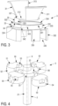
- FIGs 1 and 2 illustrate a first embodiment of a steering wheel arrangement according to the invention.
- the steering wheel arrangement 10 comprises a steering wheel 1 rotatable about a rotation axis X, a steering shaft 2, a stationary housing 3 covering at least partially the steering shaft 2 and a coupling mechanism 5 adapted to couple the steering wheel 1 to the steering shaft 2, such that rotation of the steering wheel causes rotation of the steering shaft.
- the coupling mechanism 5 is disclosed in detail in the following paragraphs and by reference to Figures 3 to 6 .
- This steering wheel arrangement 10 is adapted to be mounted to the steering column (not shown) of a vehicle, an optional stalk set 7 being positioned between the housing 3 and the steering column.
- the steering wheel arrangement 10 further comprises a central console 4 disposed in the central area of the steering wheel 1, above radial spokes 11 that connect an outer ring 12 to a central crown 14, the central console 4 being partially received inside the central crown 14.
- This central console 4 may be used for various purposes and, in particular, may incorporate one or several accessories, such as a multi-information display unit 41 and an air bag module 42 as illustrated in Figures 1 and 2 . Other accessories may be used in replacement to and in addition to these accessories.
- the central console 4 may also include a horn pad.
- switches 43 may be fixedly connected to or integral with left and right convex-shaped wings 311, 313 of the housing 3 that are radially disposed around the central crown 14, said switches 43 being electrically connected to a control unit (not shown) via electrical wires 44.
- Other electrical wires 44 may be also provided to supply current to the air bag module 42.
- the central console 4 is fixedly connected to the stationary housing 3 through any conventional connecting means. Thus, when the steering wheel 1 rotates, the central console 4 remains stationary. This stationary position of the central console 4 allows the information displayed by the multi-information display unit 41 to be always visible to the driver whatever the angular position of the steering wheel. In the same way, the stationary position of the air bag module 42 allows the air bag to be always in the best position to guarantee maximum safety for the driver. Furthermore, this non-rotating air bag module 42 avoids the addition of a clock-spring rotor on which the wires 44 are mounted, said clock-spring rotor following the rotation of the air bag module in the prior art steering wheels.
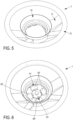
- FIG 3 is an enlarged view of the housing 3 that is illustrated in Figure 2 , the switches 43 and the wires 44 being not shown.
- This housing 3 comprises an upper part 31 and a lower part 33 connected by a single crosspiece 32.
- the upper part 31 includes a central base 312, which is substantially flat and circular, and which is aligned in a plane perpendicular to the axis X.
- the wings 311, 313 supporting the switches 43 protrude upwards from two radially opposite peripheral edges of the central base 312.
- the lower part 33 comprises a proximal portion 331 and a distal portion 332, the proximal portion 331 being closer to the upper part 31 than the distal portion 332.
- the proximal portion 331 has an annular shape and is connected to the central base 312 of the upper part 31 by the crosspiece 32, said crosspiece 32 being adapted to maintain a constant axial spacing between said central base 312 and an upper peripheral edge 334 of said proximal portion 331.
- the distal portion 332 has a parallelepiped shape and comprises an octagonal upper face 333 that is contiguous to the proximal portion 331 and eight side faces 335, four of which being provided with rectangular openings 336 through which the stalks of the stalk set 7 protrude.
- the crosspiece 32 extends between an upper end 321, which is defined by a straight end edge of the central base 312 of the upper part 31, and a lower end 322, which is defined by a hemispherical portion of the upper peripheral edge 334 of the proximal portion 331.
- the crosspiece 32 comprises a first planar section 323 aligned in an axial direction and a second planar section 324 perpendicular to the first planar section 323, the first planar section 323 being integral with the upper part 31 along the upper end 321 and the second planar section 324 being integral with the lower part 33 along the lower end 322.
- the internal periphery of the proximal portion 331 is provided with a groove 34 that defines a closed path.
- the groove 34 includes an upper section 341 and a lower section 342, said upper and lower sections 341, 342 being shaped like a portion of a ring and being axially distant from each other.
- the upper and lower sections are linked by two intermediate sections 343 extending obliquely relative the respective planes define by said upper and lower sections 341, 342.
- At least a part of the lower section 342 is axially aligned with the lower end 322 of the crosspiece 32.
- this groove 34 defines the path followed by coupling elements 50 of the steering wheel arrangement 10 during the rotation of the steering wheel.
- the upper section 341 of the groove 34 is adapted to define an upper position of said coupling elements 50 and the lower section 342 is adapted to define a lower position of said coupling elements 50.
- the groove 34 is configured such that, when the coupling elements 50 are in their lower position, they are axially positioned below the crosspiece 32, and, when the coupling elements 50 are in their upper position, they are aligned with the crosspiece 32 in a plane perpendicular to the rotation axis X.
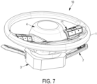
- FIG 4 is an enlarged view of the coupling mechanism 5 that is illustrated in Figure 2 .
- This coupling mechanism 5 comprises four coupling elements 50 disposed around the steering shaft 2 at regular angular intervals.
- Each coupling element 50 is formed of a substantially flat and circular base 52 and of two coupling teeth, respectively a distal coupling tooth 51 and a proximal coupling tooth 53, projecting axially from said base 52, the height of the proximal tooth 53 being greater than the height of the distal tooth 51.
- the distal coupling tooth 51 and the proximal coupling tooth 53 of each coupling element 50 are aligned in a radial direction.
- the steering shaft 2 comprises an axle 21 defining the rotation axis X and a disc-shaped tray 22 coaxially mounted on the axle 21.
- the tray 22 is provided with a series of four proximal notches 23 on its outer periphery, each proximal notch 23 being configured to slidably receive the proximal tooth 53 of one of the coupling elements 50.
- a torque can be transmitted to the steering shaft 2 when the coupling elements 50 rotate or, inversely, a torque can be transmitted to the coupling elements 50 when the steering shaft 2 rotates.
- the proximal tooth 53 axially moves inside the notch 23 depending on the position of the coupling element 50. This position results from the engagement of a hemispherical tab 54 protruding from an external side of the distal coupling tooth 51 of the coupling element 50 inside the groove 34 of the housing 3.
- the coupling element 50 when the tab 54 follows the path defined by the upper section 341 of the groove 34, the coupling element 50 is in its upper position, and, when the tab 54 follows the path defined by the lower section 342 of the groove 34, the coupling element 50 is in its lower position. In this lower position, the coupling element 50 is positioned below the crosspiece 32, thus avoiding a restriction in the movement of the coupling element 50 due to the presence of the crosspiece 32 against which the coupling element 50 would abut if it were kept constantly in its upper position.
- the specific path defined by the groove 34 thus allows a 360° rotation of the coupling element 50 about the rotation axis X.
- the rotation of the coupling elements 50 results from the rotation of the steering wheel 1.
- the central crown 14 of the steering wheel 1 is provided with a series of four distal notches 16, each distal notch 16 being defined by a pair of adjacent segments 15 protruding from the inner periphery 13 of the central crown 14.
- Each distal notch 16 is configured to receive the distal coupling tooth 51 of the coupling elements 50 when said coupling elements 50 are in their upper position (corresponding to the position of the coupling elements 50' illustrated in Figure 6 ), thus ensuring the transmission of a torque to said coupling element 50 when the steering wheel 1 rotates.
- the coupling elements 50 When the coupling elements 50 are in their lower position (corresponding to the position of the coupling element 50" illustrated in Figure 6 ), this distal tooth 51 is out of the distal notch 16, but, due to its greater height, the proximal tooth 53 is still received in the proximal notch 23. Thus, in this lower position, the torque generated by the steering wheel 1 is not transmitted to the coupling element 50". However, the coupling element 50" rotates due to the engagement of the proximal tooth 53 in the proximal notch 23 that transmits the torque generated by the steering shaft 2 under the action of the coupling elements 50'.
- the steering wheel arrangement 1 is configured such that at least three coupling elements 50 are in their upper position whatever the angular position of steering wheel 1.
- the steering wheel arrangement 1 may comprise only three coupling elements 50 or more than four coupling elements 50.
- the groove 34 may comprise two or more lower sections 342, each lower section 342 being axially aligned with a corresponding crosspiece 32 of the housing 3 that connect the upper and lower parts 31, 33.
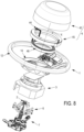
- FIGS 7 and 8 illustrate a second embodiment of a steering wheel arrangement according to the invention.
- the steering wheel arrangement 10 comprises a steering wheel 1 rotatable about a rotation axis X, a steering shaft 2, a stationary housing 3 covering at least partially the steering shaft 2 and a coupling mechanism 6 adapted to couple the steering wheel 1 to the steering shaft 2, such that rotation of the steering wheel causes rotation of the steering shaft.
- the coupling mechanism 6 is disclosed in detail in the following paragraphs and by reference to Figures 9 to 12 .
- This steering wheel arrangement 10 is adapted to be mounted to the steering column (not shown) of a vehicle, an optional stalk set 7 being positioned between the housing 3 and the steering column.
- the steering wheel arrangement 10 further comprises a central console 4 disposed in the central area of the steering wheel 1, above radial spokes 11 that connect an outer ring 12 to an annular central crown 14, the central console 4 being partially received inside the central crown 14.
- This central console 4 may be used for various purposes and, in particular, may incorporate one or several accessories, such as an air bag module 42 and electrical wires 44 adapted to supply current to the air bag module 42.
- the central console 4 is fixedly connected to the stationary housing 3 through any conventional connecting means. Thus, when the steering wheel 1 rotates, the central console 4 remains stationary. This stationary position of the central console 4 allows the air bag module 42 to be always in the best position to guarantee maximum safety for the driver.
- This non-rotating air bag module 42 is fixedly connected to a clock-spring stator 45 on which the wires 44 are mounted, said clock-spring stator 45 being housed inside the central crown 14.
- An annular ball bearing 46 coaxially mounted between the central crown 14 and the housing 3 allows the rotation of the steering wheel 1 with respect to the housing 3 about the rotation axis X.
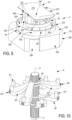
- FIG 9 is an enlarged view of the housing 3 that is illustrated in Figure 8 .
- This housing 3 comprises an upper part 31 and a lower part 33 connected by a crosspiece 32.
- the upper part 31 includes a central base 312, which is substantially flat and rectangular, and which is aligned in a plane perpendicular to the axis X.
- the lower part 33 comprises a proximal portion 331 and a distal portion 332, the proximal portion 331 being closer to the upper part 31 than the distal portion 332.
- the proximal portion 331 has an annular shape and is connected to the central base 312 of the upper part 31 by the crosspiece 32, said crosspiece 32 being adapted to maintain a constant axial spacing between said central base 312 and an upper peripheral edge 334 of said proximal portion 331.
- the distal portion 332 has a parallelepiped shape and comprises an octagonal upper face 333 that is contiguous to the proximal portion 331 and eight side faces 335, three of which being provided with rectangular openings 336 through which the stalks of the stalk set 7 protrude.
- the crosspiece 32 comprises two planar sections 324 perpendicular to the axial direction and, contiguous thereto, a substantially annular section 325 aligned in an axial direction.
- Each planar section 324 is integral with the lower part 33 along a lower end 322, which is defined by a hemispherical portion of the upper peripheral edge 334 of the proximal portion 331.
- the substantially annular section 325 is connected to the upper part 31 through four pillars 326 extending along an axial direction.
- Each pillar 326 is integral with the upper part 31 at an upper end 321.
- the internal periphery of the proximal portion 331 is provided with a groove 34 that defines a closed path.
- the groove 34 includes two upper sections 341 and two lower sections 342, said upper and lower sections 341, 342 being shaped like a portion of a ring and being axially distant from each other.
- Each upper section 341 is linked to the lower sections 342 by two intermediate sections 343 extending obliquely relative the respective planes define by said upper and lower sections 341, 342.
- At least a part of each lower section 342 is axially aligned with one lower end 322 of the crosspiece 32.
- this groove 34 defines the path followed by coupling elements 60 of the steering wheel arrangement 10 during the rotation of the steering wheel.
- each upper section 341 of the groove 34 is adapted to define an upper position of said coupling elements 60 and each lower section 342 is adapted to define a lower position of said coupling elements 60.
- the groove 34 is configured such that, when the coupling elements 60 are in their lower positions, they are axially positioned below the crosspiece 32, and, when the coupling elements 60 are in their upper position, they are aligned with the crosspiece 32 in a plane perpendicular to the rotation axis X.
- FIG 10 is an enlarged view of the coupling mechanism 6 that is illustrated in Figure 8 .
- This coupling mechanism 6 comprises four coupling elements 60 disposed around the steering shaft 2 at regular angular intervals.
- Each coupling element 60 consists in an arc-shaped spindle comprising a central ring 63 and two distal coupling pins, respectively a left coupling pin 61' and a right coupling pin 61", connected to the central ring 63 through two curved arms, respectively a left arm 62' and a right arm 62".
- the central ring 63 has a toothed inner periphery having a complementary form to the toothed outer periphery of the steering shaft 2 such that the central ring 63 is coaxially mounted on the steering shaft 2 when the teeth of the central ring 63 engage with the teeth of the steering shaft 2.
- a torque can be transmitted to the steering shaft 2 when the coupling elements 60 rotate or, inversely, a torque can be transmitted to the coupling elements 60 when the steering shaft 2 rotates.
- this arrangement allows an axial movement of the coupling element 60 relative to the steering shaft 2.
- the central ring 63 axially moves along the steering shaft 2 depending on the position of the coupling element 60.
- the coupling element 60 In this lower position, the coupling element 60 is positioned below the crosspiece 32, thus avoiding a restriction in the movement of the coupling element 60 due to the presence of the crosspiece 32 against which the coupling element 60 would abut if it were kept constantly in its upper position.
- the specific path defined by the groove 34 thus allows a 360° rotation of the coupling element 60 about the rotation axis X.
- the rotation of the coupling elements 60 results from the rotation of the steering wheel 1.
- the central crown 14 of the steering wheel 1 is provided at its bottom face 141, which faces the housing 3, with a series of eight axially oriented apertures 18.
- the apertures 18 are configured to receive the coupling pins 61', 61" of the coupling elements 60 when the coupling elements 60 are in their upper position (corresponding to the position of the coupling element 60' illustrated in Figure 12 ), thus ensuring the transmission of a torque to said coupling element 60 when the steering wheel 1 rotates.
- their coupling pins 61', 61" are out of the apertures 18.
- the steering wheel arrangement 1 is configured such that at least one coupling element 60 is in its upper position whatever the angular position of steering wheel 1.
- the steering wheel arrangement 1 may comprise only three coupling elements 60 or more than four coupling elements 60.
- the groove 34 may comprise only one lower section 342 or three or more lower sections 342, each lower section 342 being axially aligned with a corresponding crosspiece 32 of the housing 3 that connect together the upper and lower parts 31, 33.
Landscapes
- Engineering & Computer Science (AREA)
- Chemical & Material Sciences (AREA)
- Combustion & Propulsion (AREA)
- Transportation (AREA)
- Mechanical Engineering (AREA)
- Steering Controls (AREA)
Claims (15)
- Agencement de volant de direction (10), comprenant :- un volant de direction (1) pouvant tourner autour d'un axe de rotation (X),- un arbre de direction (2),- un boîtier fixe (3) couvrant au moins partiellement l'arbre de direction (2) et supportant au moins un accessoire (41, 42, 43),- une pluralité d'éléments d'accouplement (50, 60) adaptés pour coupler le volant de direction (1) à l'arbre de direction (2), de sorte que la rotation du volant de direction entraîne la rotation de l'arbre de direction,caractérisé en ce que chaque élément d'accouplement (50, 60) est solidaire en rotation de l'arbre de direction (2) et mobile en coulissement le long d'une direction axiale entre une position supérieure et une position inférieure, et en ce que chaque élément d'accouplement (50, 60) est connecté de manière amovible au volant de direction (1), chaque élément d'accouplement (50, 60) étant connecté au volant de direction (1) dans sa position supérieure, de sorte que la rotation du volant de direction (1) entraîne la rotation de l'élément d'accouplement (50 , 60), et étant déconnecté du volant de direction (1) dans sa position inférieure, de sorte que la rotation du volant de direction (1) n'entraîne pas la rotation de l'élément d'accouplement (50, 60).
- Agencement de volant de direction (10) selon la revendication 1, dans lequel le boîtier (3) comprend une partie supérieure (31) et une partie inférieure (33), lesdites parties supérieure et inférieure (31, 33) étant connectées par au moins une traverse (32), l'au moins une traverse (32) étant positionnée axialement au-dessus des éléments d'accouplement (50, 60) lorsque lesdits éléments d'accouplement (50, 60) sont dans leur position inférieure, permettant ainsi une rotation desdits éléments d'accouplement autour de l'axe de rotation, et l'au moins une traverse étant alignée avec les éléments d'accouplement (50, 60) dans un plan perpendiculaire à l'axe de rotation (X) lorsque lesdits éléments d'accouplement (50, 60) sont dans leur position supérieure.
- Agencement de volant de direction (10) selon la revendication 1 ou la revendication 2, dans lequel chaque élément d'accouplement (50, 60) comprend une patte hémisphérique (54, 64', 64"), ladite patte (54, 64', 64") étant engagée à l'intérieur d'une rainure (34) du boîtier (3), permettant ainsi la rotation de l'élément d'accouplement (50, 60) autour de l'axe de rotation (X).
- Agencement de volant de direction (10) selon la revendication 3, dans lequel la rainure (34) définit un chemin fermé de sorte que, lorsque la patte (54, 64', 64") suit entièrement ledit chemin fermé, chaque élément d'accouplement (50, 60) tourne de 360° autour de l'axe de rotation (X).
- Agencement de volant de direction (10) selon la revendication 3 ou la revendication 4, dans lequel la rainure (34) comprend au moins une section supérieure (341) et au moins une section inférieure (342), lesdites sections supérieure et inférieure (341, 342) étant axialement distantes l'une de l'autre, l'au moins une section supérieure (341) définissant la position supérieure des éléments d'accouplement (50, 60) et l'au moins une section inférieure (342) définissant la position inférieure des éléments d'accouplement (50, 60).
- Agencement de volant de direction (10) selon l'une des revendications 1 à 5, dans lequel chaque élément d'accouplement (50) est formé d'une base sensiblement plate et circulaire (52) et de deux dents, respectivement une dent distale (51) et une dent proximale (53), faisant saillie axialement depuis ladite base (52), lesdites dents distale et proximale (51, 53) étant alignées dans une direction radiale, dans lequel le volant de direction (1) comprend une couronne centrale (14), ladite couronne centrale (14) étant pourvue d'une série d'encoches distales (16) sur sa périphérie interne (13), chaque encoche distale (16) étant configurée pour recevoir la dent distale (51) de l'un des éléments d'accouplement (50) lorsque ledit élément d'accouplement (50) est dans sa position supérieure, assurant ainsi la transmission d'un couple audit élément d'accouplement (50) lorsque le volant de direction (1) tourne, ladite dent distale (51) étant hors de ladite encoche distale (16) lorsque ledit élément d'accouplement (50) est dans sa position inférieure, et dans lequel l'arbre de direction (2) comprend un plateau en forme de disque (22) pourvu d'une série d'encoches proximales (23) sur sa périphérie externe, chaque encoche proximale (23) étant configurée pour recevoir la dent proximale (53) de l'un des éléments d'accouplement (50) quelle que soit la position dudit élément d'accouplement, assurant ainsi la transmission d'un couple à l'arbre de direction (2) lorsque l'élément d'accouplement (50) tourne ou vice-versa.
- Agencement de volant de direction (10) selon la revendication 6, dans lequel la hauteur de la dent proximale (53) est supérieure à la hauteur de la dent distale (51), de sorte que la dent proximale (53) soit toujours reçue dans l'encoche proximale (23) dans la position inférieure de l'élément d'accouplement (50).
- Agencement de volant de direction (10) selon l'une des revendications 1 à 5, dans lequel l'arbre de direction (2) a une périphérie externe dentée, dans lequel chaque élément d'accouplement (60) consiste en une tige en forme d'arc comprenant un anneau central (63) et deux broches distales, respectivement une broche gauche (61') et une broche droite (61"), connectées à celui-ci par l'intermédiaire de deux bras incurvés, respectivement un bras gauche (62') et un bras droit (62"), dans lequel l'anneau central (63) présente une périphérie interne dentée, ledit anneau central (63) étant monté coaxialement sur l'arbre de direction (2) de sorte que les dents de l'anneau central (63) s'engagent avec les dents de l'arbre de direction (2), assurant ainsi la transmission d'un couple à l'arbre de direction (2) lorsque l'élément d'accouplement (60) tourne ou vice versa tout en autorisant un mouvement axial de l'élément d'accouplement (60) par rapport à l'arbre de direction (2), et dans lequel le volant de direction (1) comprend une couronne centrale (14), ladite couronne centrale (14) étant pourvue d'une série d'ouvertures orientées axialement (18) qui sont adaptées pour recevoir les broches gauche et droite (61', 61") des éléments d'accouplement (60) lorsque les éléments d'accouplement sont dans leur position supérieure, assurant ainsi la transmission d'un couple auxdits éléments d'accouplement (60) lorsque le volant de direction (1) tourne, lesdites broches gauche et droite (61', 61") étant hors desdites ouvertures (18) lorsque les éléments d'accouplement sont dans leur position inférieure.
- Agencement de volant de direction (10) selon l'une des revendications 1 à 8, dans lequel l'au moins un accessoire (41, 42, 43) est connecté de manière fixe au boîtier (3).
- Agencement de volant de direction (10) selon l'une des revendications 1 à 9, dans lequel l'au moins un accessoire (43) est solidaire du boîtier (3).
- Agencement de volant de direction (10) selon l'une des revendications 6 à 9, dans lequel la couronne centrale (14) reçoit au moins partiellement l'au moins un accessoire (41, 42).
- Agencement de volant de direction (10) selon la revendication 11, dans lequel la couronne centrale (14) reçoit un élément de support annulaire (45), qui est connecté de manière fixe au boîtier (3) et qui supporte des fils électriques (44).
- Agencement de volant de direction (10) selon la revendication 12, comprenant en outre un roulement à billes annulaire (46) monté coaxialement entre la couronne centrale (14) et le boîtier (3), ledit roulement à billes (46) permettant la rotation du volant de direction (1) par rapport au boîtier (3) autour de l'axe de rotation (X).
- Agencement de volant de direction (10) selon l'une des revendications 1 à 13, dans lequel l'au moins un accessoire est sélectionné dans le groupe constitué d'une unité d'affichage (41), d'un module de coussin de sécurité gonflable (42), d'un commutateur (43) et d'un klaxon.
- Véhicule comprenant un agencement de volant de direction (10) selon l'une des revendications 1 à 14.
Priority Applications (3)
| Application Number | Priority Date | Filing Date | Title |
|---|---|---|---|
| EP21212064.6A EP4190671B1 (fr) | 2021-12-02 | 2021-12-02 | Agencement de volant de direction |
| CN202211527450.7A CN116215641A (zh) | 2021-12-02 | 2022-12-01 | 方向盘装置 |
| US18/061,179 US11780488B2 (en) | 2021-12-02 | 2022-12-02 | Steering wheel arrangement |
Applications Claiming Priority (1)
| Application Number | Priority Date | Filing Date | Title |
|---|---|---|---|
| EP21212064.6A EP4190671B1 (fr) | 2021-12-02 | 2021-12-02 | Agencement de volant de direction |
Publications (3)
| Publication Number | Publication Date |
|---|---|
| EP4190671A1 EP4190671A1 (fr) | 2023-06-07 |
| EP4190671C0 EP4190671C0 (fr) | 2024-06-12 |
| EP4190671B1 true EP4190671B1 (fr) | 2024-06-12 |
Family
ID=78821567
Family Applications (1)
| Application Number | Title | Priority Date | Filing Date |
|---|---|---|---|
| EP21212064.6A Active EP4190671B1 (fr) | 2021-12-02 | 2021-12-02 | Agencement de volant de direction |
Country Status (3)
| Country | Link |
|---|---|
| US (1) | US11780488B2 (fr) |
| EP (1) | EP4190671B1 (fr) |
| CN (1) | CN116215641A (fr) |
Family Cites Families (13)
| Publication number | Priority date | Publication date | Assignee | Title |
|---|---|---|---|---|
| GB1216324A (en) * | 1967-06-26 | 1970-12-16 | Lucas Industries Ltd | Means for mounting controls in a road vehicle |
| US3548128A (en) * | 1969-07-11 | 1970-12-15 | Palmer B Willett | Adjustable steering wheel |
| DE2131902A1 (de) * | 1971-06-26 | 1972-12-28 | Heckler & Koch Gmbh | Lenkrad fuer ein Kraftfahrzeug od.dgl. |
| JPS57198141A (en) * | 1981-05-29 | 1982-12-04 | Matsushita Electric Ind Co Ltd | Operation switch for car |
| JPS5836743A (ja) * | 1981-08-31 | 1983-03-03 | Tokai Rika Co Ltd | ハンドル上スイツチベ−スの取付構造 |
| JPS59156862A (ja) * | 1983-02-25 | 1984-09-06 | Mazda Motor Corp | 自動車のステアリング装置 |
| DE4428883C1 (de) * | 1994-08-17 | 1995-12-14 | Kostal Leopold Gmbh & Co Kg | Einrichtung für Kraftfahrzeuge |
| US5855451A (en) * | 1997-04-21 | 1999-01-05 | General Motors Corporation | Coupling between steering wheel and steering shaft |
| US5855449A (en) * | 1997-06-09 | 1999-01-05 | General Motors Corporation | Coupling between steering shaft and steering wheel |
| WO2005094528A2 (fr) * | 2004-03-25 | 2005-10-13 | Timken Us Corporation | Ensemble de montage de roue directrice |
| US7104821B2 (en) * | 2004-09-16 | 2006-09-12 | Alps Electric Co., Ltd. | Rotary connector |
| DE102004059551A1 (de) * | 2004-12-10 | 2006-06-22 | Leopold Kostal Gmbh & Co. Kg | Lenkradanordnung für ein Fahrzeug |
| ITBO20140081U1 (it) * | 2014-09-30 | 2016-03-30 | I F R A S R L | Un organo per il controllo della direzione di un veicolo, in particolare di un veicolo nautico. |
-
2021
- 2021-12-02 EP EP21212064.6A patent/EP4190671B1/fr active Active
-
2022
- 2022-12-01 CN CN202211527450.7A patent/CN116215641A/zh active Pending
- 2022-12-02 US US18/061,179 patent/US11780488B2/en active Active
Also Published As
| Publication number | Publication date |
|---|---|
| US11780488B2 (en) | 2023-10-10 |
| EP4190671A1 (fr) | 2023-06-07 |
| EP4190671C0 (fr) | 2024-06-12 |
| CN116215641A (zh) | 2023-06-06 |
| US20230174134A1 (en) | 2023-06-08 |
Similar Documents
| Publication | Publication Date | Title |
|---|---|---|
| JPH0629028B2 (ja) | 車両用操向ハンドルにおける電導性巻回ケ−ブルの中立位置表示装置 | |
| US11407436B2 (en) | Steering wheel with fixed center | |
| JP2008007075A (ja) | 舵角センサ組み込み式回転コネクタ装置 | |
| US20080277178A1 (en) | Steering wheel assembly with centrally located stationary support member | |
| JP5097364B2 (ja) | 舵角センサ組み込み式回転コネクタ装置 | |
| EP4190671B1 (fr) | Agencement de volant de direction | |
| US11673602B2 (en) | Steering wheel arrangement | |
| CN213323325U (zh) | 一种双轮立式舵轮 | |
| US6164690A (en) | Steering wheel | |
| US20130276571A1 (en) | Advanced Steering Wheel | |
| JPH01148640A (ja) | 自動車のステアリング装置 | |
| CN101746405B (zh) | 操纵把手 | |
| US20120144954A1 (en) | Advanced steering wheel | |
| US3248965A (en) | Steering mechanism | |
| JPS5940959A (ja) | ステアリング装置のスイツチ装置 | |
| JP2013174517A (ja) | 操舵角検出装置 | |
| US6231074B1 (en) | Steering wheel | |
| US6290254B1 (en) | Steering wheel | |
| KR100331424B1 (ko) | 자동차의 조향위치 표시장치 | |
| KR20170101663A (ko) | 자동차 조향장치 | |
| JPH0523984B2 (fr) | ||
| GB2245346A (en) | Vehicle steering wheel and column assembly | |
| EP1233887B1 (fr) | Dispositif pour colonne de direction | |
| KR19980059414A (ko) | 지게차의 핸들장치 | |
| WO2024242617A1 (fr) | Actionneur de volant et ensemble armature de volant pour un ensemble de direction à commande électrique |
Legal Events
| Date | Code | Title | Description |
|---|---|---|---|
| PUAI | Public reference made under article 153(3) epc to a published international application that has entered the european phase |
Free format text: ORIGINAL CODE: 0009012 |
|
| STAA | Information on the status of an ep patent application or granted ep patent |
Free format text: STATUS: THE APPLICATION HAS BEEN PUBLISHED |
|
| AK | Designated contracting states |
Kind code of ref document: A1 Designated state(s): AL AT BE BG CH CY CZ DE DK EE ES FI FR GB GR HR HU IE IS IT LI LT LU LV MC MK MT NL NO PL PT RO RS SE SI SK SM TR |
|
| STAA | Information on the status of an ep patent application or granted ep patent |
Free format text: STATUS: REQUEST FOR EXAMINATION WAS MADE |
|
| 17P | Request for examination filed |
Effective date: 20231025 |
|
| RBV | Designated contracting states (corrected) |
Designated state(s): AL AT BE BG CH CY CZ DE DK EE ES FI FR GB GR HR HU IE IS IT LI LT LU LV MC MK MT NL NO PL PT RO RS SE SI SK SM TR |
|
| GRAP | Despatch of communication of intention to grant a patent |
Free format text: ORIGINAL CODE: EPIDOSNIGR1 |
|
| STAA | Information on the status of an ep patent application or granted ep patent |
Free format text: STATUS: GRANT OF PATENT IS INTENDED |
|
| INTG | Intention to grant announced |
Effective date: 20240306 |
|
| GRAS | Grant fee paid |
Free format text: ORIGINAL CODE: EPIDOSNIGR3 |
|
| GRAA | (expected) grant |
Free format text: ORIGINAL CODE: 0009210 |
|
| STAA | Information on the status of an ep patent application or granted ep patent |
Free format text: STATUS: THE PATENT HAS BEEN GRANTED |
|
| AK | Designated contracting states |
Kind code of ref document: B1 Designated state(s): AL AT BE BG CH CY CZ DE DK EE ES FI FR GB GR HR HU IE IS IT LI LT LU LV MC MK MT NL NO PL PT RO RS SE SI SK SM TR |
|
| REG | Reference to a national code |
Ref country code: GB Ref legal event code: FG4D |
|
| REG | Reference to a national code |
Ref country code: CH Ref legal event code: EP |
|
| REG | Reference to a national code |
Ref country code: DE Ref legal event code: R096 Ref document number: 602021014309 Country of ref document: DE |
|
| REG | Reference to a national code |
Ref country code: IE Ref legal event code: FG4D |
|
| U01 | Request for unitary effect filed |
Effective date: 20240617 |
|
| U07 | Unitary effect registered |
Designated state(s): AT BE BG DE DK EE FI FR IT LT LU LV MT NL PT SE SI Effective date: 20240627 |
|
| PG25 | Lapsed in a contracting state [announced via postgrant information from national office to epo] |
Ref country code: HR Free format text: LAPSE BECAUSE OF FAILURE TO SUBMIT A TRANSLATION OF THE DESCRIPTION OR TO PAY THE FEE WITHIN THE PRESCRIBED TIME-LIMIT Effective date: 20240612 |
|
| PG25 | Lapsed in a contracting state [announced via postgrant information from national office to epo] |
Ref country code: GR Free format text: LAPSE BECAUSE OF FAILURE TO SUBMIT A TRANSLATION OF THE DESCRIPTION OR TO PAY THE FEE WITHIN THE PRESCRIBED TIME-LIMIT Effective date: 20240913 |
|
| PG25 | Lapsed in a contracting state [announced via postgrant information from national office to epo] |
Ref country code: ES Free format text: LAPSE BECAUSE OF FAILURE TO SUBMIT A TRANSLATION OF THE DESCRIPTION OR TO PAY THE FEE WITHIN THE PRESCRIBED TIME-LIMIT Effective date: 20240612 |
|
| PG25 | Lapsed in a contracting state [announced via postgrant information from national office to epo] |
Ref country code: NO Free format text: LAPSE BECAUSE OF FAILURE TO SUBMIT A TRANSLATION OF THE DESCRIPTION OR TO PAY THE FEE WITHIN THE PRESCRIBED TIME-LIMIT Effective date: 20240912 Ref country code: HR Free format text: LAPSE BECAUSE OF FAILURE TO SUBMIT A TRANSLATION OF THE DESCRIPTION OR TO PAY THE FEE WITHIN THE PRESCRIBED TIME-LIMIT Effective date: 20240612 Ref country code: GR Free format text: LAPSE BECAUSE OF FAILURE TO SUBMIT A TRANSLATION OF THE DESCRIPTION OR TO PAY THE FEE WITHIN THE PRESCRIBED TIME-LIMIT Effective date: 20240913 Ref country code: ES Free format text: LAPSE BECAUSE OF FAILURE TO SUBMIT A TRANSLATION OF THE DESCRIPTION OR TO PAY THE FEE WITHIN THE PRESCRIBED TIME-LIMIT Effective date: 20240612 Ref country code: RS Free format text: LAPSE BECAUSE OF FAILURE TO SUBMIT A TRANSLATION OF THE DESCRIPTION OR TO PAY THE FEE WITHIN THE PRESCRIBED TIME-LIMIT Effective date: 20240912 |
|
| PG25 | Lapsed in a contracting state [announced via postgrant information from national office to epo] |
Ref country code: PL Free format text: LAPSE BECAUSE OF FAILURE TO SUBMIT A TRANSLATION OF THE DESCRIPTION OR TO PAY THE FEE WITHIN THE PRESCRIBED TIME-LIMIT Effective date: 20240612 |
|
| PG25 | Lapsed in a contracting state [announced via postgrant information from national office to epo] |
Ref country code: IS Free format text: LAPSE BECAUSE OF FAILURE TO SUBMIT A TRANSLATION OF THE DESCRIPTION OR TO PAY THE FEE WITHIN THE PRESCRIBED TIME-LIMIT Effective date: 20241012 |
|
| PG25 | Lapsed in a contracting state [announced via postgrant information from national office to epo] |
Ref country code: CZ Free format text: LAPSE BECAUSE OF FAILURE TO SUBMIT A TRANSLATION OF THE DESCRIPTION OR TO PAY THE FEE WITHIN THE PRESCRIBED TIME-LIMIT Effective date: 20240612 |
|
| PG25 | Lapsed in a contracting state [announced via postgrant information from national office to epo] |
Ref country code: RO Free format text: LAPSE BECAUSE OF FAILURE TO SUBMIT A TRANSLATION OF THE DESCRIPTION OR TO PAY THE FEE WITHIN THE PRESCRIBED TIME-LIMIT Effective date: 20240612 Ref country code: SK Free format text: LAPSE BECAUSE OF FAILURE TO SUBMIT A TRANSLATION OF THE DESCRIPTION OR TO PAY THE FEE WITHIN THE PRESCRIBED TIME-LIMIT Effective date: 20240612 |
|
| PG25 | Lapsed in a contracting state [announced via postgrant information from national office to epo] |
Ref country code: SM Free format text: LAPSE BECAUSE OF FAILURE TO SUBMIT A TRANSLATION OF THE DESCRIPTION OR TO PAY THE FEE WITHIN THE PRESCRIBED TIME-LIMIT Effective date: 20240612 |
|
| U20 | Renewal fee for the european patent with unitary effect paid |
Year of fee payment: 4 Effective date: 20241225 |
|
| PG25 | Lapsed in a contracting state [announced via postgrant information from national office to epo] |
Ref country code: SM Free format text: LAPSE BECAUSE OF FAILURE TO SUBMIT A TRANSLATION OF THE DESCRIPTION OR TO PAY THE FEE WITHIN THE PRESCRIBED TIME-LIMIT Effective date: 20240612 Ref country code: SK Free format text: LAPSE BECAUSE OF FAILURE TO SUBMIT A TRANSLATION OF THE DESCRIPTION OR TO PAY THE FEE WITHIN THE PRESCRIBED TIME-LIMIT Effective date: 20240612 Ref country code: RO Free format text: LAPSE BECAUSE OF FAILURE TO SUBMIT A TRANSLATION OF THE DESCRIPTION OR TO PAY THE FEE WITHIN THE PRESCRIBED TIME-LIMIT Effective date: 20240612 Ref country code: PL Free format text: LAPSE BECAUSE OF FAILURE TO SUBMIT A TRANSLATION OF THE DESCRIPTION OR TO PAY THE FEE WITHIN THE PRESCRIBED TIME-LIMIT Effective date: 20240612 Ref country code: IS Free format text: LAPSE BECAUSE OF FAILURE TO SUBMIT A TRANSLATION OF THE DESCRIPTION OR TO PAY THE FEE WITHIN THE PRESCRIBED TIME-LIMIT Effective date: 20241012 Ref country code: CZ Free format text: LAPSE BECAUSE OF FAILURE TO SUBMIT A TRANSLATION OF THE DESCRIPTION OR TO PAY THE FEE WITHIN THE PRESCRIBED TIME-LIMIT Effective date: 20240612 |
|
| PLBE | No opposition filed within time limit |
Free format text: ORIGINAL CODE: 0009261 |
|
| STAA | Information on the status of an ep patent application or granted ep patent |
Free format text: STATUS: NO OPPOSITION FILED WITHIN TIME LIMIT |
|
| 26N | No opposition filed |
Effective date: 20250313 |
|
| PG25 | Lapsed in a contracting state [announced via postgrant information from national office to epo] |
Ref country code: MC Free format text: LAPSE BECAUSE OF FAILURE TO SUBMIT A TRANSLATION OF THE DESCRIPTION OR TO PAY THE FEE WITHIN THE PRESCRIBED TIME-LIMIT Effective date: 20240612 |
|
| REG | Reference to a national code |
Ref country code: CH Ref legal event code: PL |
|
| PG25 | Lapsed in a contracting state [announced via postgrant information from national office to epo] |
Ref country code: CH Free format text: LAPSE BECAUSE OF NON-PAYMENT OF DUE FEES Effective date: 20241231 |
|
| PG25 | Lapsed in a contracting state [announced via postgrant information from national office to epo] |
Ref country code: IE Free format text: LAPSE BECAUSE OF NON-PAYMENT OF DUE FEES Effective date: 20241202 |
|
| U20 | Renewal fee for the european patent with unitary effect paid |
Year of fee payment: 5 Effective date: 20251223 |
|
| PG25 | Lapsed in a contracting state [announced via postgrant information from national office to epo] |
Ref country code: CY Free format text: LAPSE BECAUSE OF FAILURE TO SUBMIT A TRANSLATION OF THE DESCRIPTION OR TO PAY THE FEE WITHIN THE PRESCRIBED TIME-LIMIT; INVALID AB INITIO Effective date: 20211202 |