EP4190701A1 - Avertissement de rotation - Google Patents
Avertissement de rotation Download PDFInfo
- Publication number
- EP4190701A1 EP4190701A1 EP22208820.5A EP22208820A EP4190701A1 EP 4190701 A1 EP4190701 A1 EP 4190701A1 EP 22208820 A EP22208820 A EP 22208820A EP 4190701 A1 EP4190701 A1 EP 4190701A1
- Authority
- EP
- European Patent Office
- Prior art keywords
- aircraft
- rotation
- landing gear
- warning
- threshold
- Prior art date
- Legal status (The legal status is an assumption and is not a legal conclusion. Google has not performed a legal analysis and makes no representation as to the accuracy of the status listed.)
- Withdrawn
Links
- 238000012544 monitoring process Methods 0.000 claims abstract description 21
- 230000006835 compression Effects 0.000 claims description 28
- 238000007906 compression Methods 0.000 claims description 28
- 238000000034 method Methods 0.000 claims description 27
- 230000002028 premature Effects 0.000 claims description 6
- 230000002401 inhibitory effect Effects 0.000 claims description 2
- 238000009434 installation Methods 0.000 claims description 2
- 230000004044 response Effects 0.000 description 3
- 230000009471 action Effects 0.000 description 2
- 230000001960 triggered effect Effects 0.000 description 2
- 241000272517 Anseriformes Species 0.000 description 1
- 238000013459 approach Methods 0.000 description 1
- 230000008901 benefit Effects 0.000 description 1
- 230000008859 change Effects 0.000 description 1
- 239000012636 effector Substances 0.000 description 1
- 230000007613 environmental effect Effects 0.000 description 1
- 239000000446 fuel Substances 0.000 description 1
- 230000005484 gravity Effects 0.000 description 1
- 230000001771 impaired effect Effects 0.000 description 1
- 230000005764 inhibitory process Effects 0.000 description 1
- 238000012986 modification Methods 0.000 description 1
- 230000004048 modification Effects 0.000 description 1
- 230000009467 reduction Effects 0.000 description 1
- 230000004043 responsiveness Effects 0.000 description 1
- 230000000284 resting effect Effects 0.000 description 1
- 230000007704 transition Effects 0.000 description 1
- 230000000007 visual effect Effects 0.000 description 1
Images



Classifications
-
- B—PERFORMING OPERATIONS; TRANSPORTING
- B64—AIRCRAFT; AVIATION; COSMONAUTICS
- B64C—AEROPLANES; HELICOPTERS
- B64C25/00—Alighting gear
- B64C25/001—Devices not provided for in the groups B64C25/02 - B64C25/68
-
- B—PERFORMING OPERATIONS; TRANSPORTING
- B64—AIRCRAFT; AVIATION; COSMONAUTICS
- B64D—EQUIPMENT FOR FITTING IN OR TO AIRCRAFT; FLIGHT SUITS; PARACHUTES; ARRANGEMENT OR MOUNTING OF POWER PLANTS OR PROPULSION TRANSMISSIONS IN AIRCRAFT
- B64D45/00—Aircraft indicators or protectors not otherwise provided for
- B64D45/0005—Devices specially adapted to indicate the position of a movable element of the aircraft, e.g. landing gear
-
- B—PERFORMING OPERATIONS; TRANSPORTING
- B64—AIRCRAFT; AVIATION; COSMONAUTICS
- B64C—AEROPLANES; HELICOPTERS
- B64C25/00—Alighting gear
- B64C25/02—Undercarriages
- B64C25/08—Undercarriages non-fixed, e.g. jettisonable
- B64C25/10—Undercarriages non-fixed, e.g. jettisonable retractable, foldable, or the like
- B64C25/18—Operating mechanisms
- B64C25/26—Control or locking systems therefor
- B64C25/28—Control or locking systems therefor with indicating or warning devices
-
- B—PERFORMING OPERATIONS; TRANSPORTING
- B64—AIRCRAFT; AVIATION; COSMONAUTICS
- B64D—EQUIPMENT FOR FITTING IN OR TO AIRCRAFT; FLIGHT SUITS; PARACHUTES; ARRANGEMENT OR MOUNTING OF POWER PLANTS OR PROPULSION TRANSMISSIONS IN AIRCRAFT
- B64D43/00—Arrangements or adaptations of instruments
-
- B—PERFORMING OPERATIONS; TRANSPORTING
- B64—AIRCRAFT; AVIATION; COSMONAUTICS
- B64D—EQUIPMENT FOR FITTING IN OR TO AIRCRAFT; FLIGHT SUITS; PARACHUTES; ARRANGEMENT OR MOUNTING OF POWER PLANTS OR PROPULSION TRANSMISSIONS IN AIRCRAFT
- B64D45/00—Aircraft indicators or protectors not otherwise provided for
- B64D45/04—Landing aids; Safety measures to prevent collision with earth's surface
-
- G—PHYSICS
- G08—SIGNALLING
- G08G—TRAFFIC CONTROL SYSTEMS
- G08G5/00—Traffic control systems for aircraft
- G08G5/20—Arrangements for acquiring, generating, sharing or displaying traffic information
Definitions
- the present invention relates to a method for warning of premature rotation of an aircraft during takeoff, and a system and aircraft configured to generate a warning when conditions of premature rotation are detected.
- an aircraft rotates around its pitch axis so as to climb away from a runway.
- the pilot of the aircraft should be sure to rotate the aircraft appropriately - in terms of timing during the takeoff as well as the rate of the rotation.
- the climb rate achieved by the aircraft may be less than is desirable for clearance of obstructions near the runway. Accordingly, systems also exist to increase the rotation rate of the aircraft or warn of under-rotation to maximise aircraft performance.
- V R the rotation speed at which the pilot should commence rotation of the aircraft. If the pilot commands rotation of the aircraft before V R , the performance of the aircraft is impaired and a longer takeoff run may be necessary. Moreover, if the pilot corrects the early rotation with a pitch down command, this can lead to a bumpy ride for any passengers or cargo in the aircraft.
- Pilots are trained to calculate an appropriate V R and to verbally identify when it is reached before commanding any rotation from the aircraft. It is an aim of this disclosure to provide a system and method to assist pilots by warning of early rotation of an aircraft or preventing early rotation continuing.
- a first aspect of the present invention provides a method of warning of early rotation of an aircraft during takeoff, the aircraft comprising a nose landing gear and a controller, the method comprising: monitoring, at the controller, the airspeed of the aircraft, the commanded rotation rate of the aircraft, and the state of compression of the nose landing gear of the aircraft; and triggering a warning when: the airspeed of the aircraft is below a speed threshold; the commanded rotation rate of the aircraft is above a rotation threshold; and the state of compression of the nose landing gear of the aircraft is below a compression threshold.
- the airspeed of the aircraft is determined by combining a measured wind velocity with a measured ground velocity.
- the speed threshold is a predetermined rotation speed for the aircraft.
- the commanded rotation rate is determined by monitoring one or more control inputs made for the aircraft.
- the commanded rotation rate is determined by monitoring one or more control outputs sent to one or more control surfaces of the aircraft.
- the commanded rotation rate is determined by measuring the position of a control surface on the aircraft.
- the rotation threshold is 1 degrees per second.
- the nose landing gear comprises a compressible member and the state of compression of the nose landing gear is determined by monitoring the length of the compressible member.
- the state of compression of the nose landing gear is inferred by measuring the distance between the nose of the aircraft and the ground beneath it.
- the compression threshold is zero such that the threshold is met when there is no compression of the nose landing gear.
- the warning is an auditory warning in the cockpit.
- the method may further comprise a step of inhibiting the commanded rotation rate of the aircraft during the warning.
- the method further comprises deactivating the warning on detecting an extension of a main landing gear strut extending on the aircraft.
- a second aspect of the invention provides a controller for installation in an aircraft, the controller being configured to trigger a warning on detecting premature rotation of the aircraft during takeoff, the aircraft comprising a nose landing gear; the controller comprising: a first input for receiving the airspeed of the aircraft; a second input for receiving the commanded rotation rate of the aircraft; a third input for receiving the state of compression of the nose landing gear of the aircraft; and a warning output for indicating premature rotation of the aircraft during takeoff; the controller being configured to monitor the first, second and third inputs during takeoff of the aircraft, and send a signal on the warning output when: the value received on the first input is below a speed threshold; the value received on the second input is above a rotation threshold; and the value received on the third input is below a compression threshold.
- an aircraft may comprising the controller.
- a third aspect of the invention provides a data carrier comprising machine-readable instructions for the operation of a controller to perform the method herein described.
- V R is the speed at which the pilot should begin to apply a pitch up command to cause the aircraft to begin to rotate off the runway. Because it varies with aircraft load and environmental conditions it is typically determined on a flight-by-flight basis.
- Aircraft 2 has Main Landing Gear (MLG) 4, which support the majority of the weight of the aircraft.
- MLG Main Landing Gear
- the MLG may comprise a number of sets of wheels around the centre of gravity of the aircraft 2.
- the aircraft 2 further has Nose Landing Gear (NLG) 6 which support the nose of the aircraft.
- V R Main Landing Gear
- NLG Nose Landing Gear
- both the MLG 4 and NLG 6 should remain in contact with the runway.
- the pilot may begin to cause the aircraft to pitch up, rotating the aircraft 2 around the MLG 4 as shown in Figure 1b .
- the aircraft 2 is shown having begun rotation around MLG 4. NLG 6 is no longer in contact with the runway whilst MLG 4 remain in contact with the runway. A portion of the weight of the aircraft is supported by aerodynamic forces acting upon it and a portion by MLG 4. In this orientation, the tail 8 of the aircraft is brought into proximity with the runway. The aircraft continues to rotate and to accelerate past V R until at least the Minimum Unstick Velocity (V MU ) at which the aircraft may takeoff and become fully airborne, as shown in Figure 1c . In order to ensure an appropriate margin of error, a pilot should accelerate to the takeoff safety speed, V 2 , before becoming fully airborne.
- V MU Minimum Unstick Velocity
- Figure 1c shows the aircraft 2 as fully airborne. Both NLG 6 and MLG 4 are no longer in contact with the runway, and the weight of the aircraft 2 is supported by aerodynamic forces acting upon it. The aircraft 2 may climb into the atmosphere. In order to enable an appropriate climb rate so as to avoid obstructions around the runway, further rotation of the aircraft to achieve an optimum angle of climb may be required.
- the rate of rotation and the eventual climb of the aircraft during the takeoff are very important for the proper performance of the aircraft. It is desirable that the aircraft 2 promptly adopts a sufficient rate of climb after takeoff in order to maximise its clearance of any obstacles that may be in the area around the runway. In order to achieve this the aircraft should promptly rotate to adopt an appropriate climb. Under rotation results in a reduction of such clearance, so aircraft may feature a number of systems that aid the pilot to achieve an appropriate level of rotation. For example, there may be markings on an artificial horizon or heads-up display that mark a desired climb angle that the pilot should achieve. Furthermore, systems exist that increase the rotation rate above that commanded by the pilot in order to provide satisfactory performance.
- a pilot may apply a backward pressure on the controls of the aircraft 2, commanding a rotation of the aircraft, before the aircraft reaches V R . This might happen for a number of reasons, such as the pilot accidentally resting their hands on the controls with too much force, or the pilot mistaking the current airspeed of the aircraft. Since different aircraft may feature different response curves to control inputs, a pilot may be making what they consider a minimal input which actually amounts to a commanded rotation rate that would cause the aircraft to pitch up.
- any system that aims to support the pilot to avoid early rotation is one that is compatible with and does not interfere the action of existing systems.
- a controller may be provided to monitor the aircraft condition and warn of early rotation.
- the aircraft 2 is shown as comprising such a controller 10.
- the controller 10 monitors data relating to the airspeed of the aircraft 2, the commanded rotation rate of the aircraft 2, and the state of compression of the nose landing gear 6 of the aircraft 2 via first, second and third inputs.
- the controller 10 is adapted to trigger a warning via a warning output upon determining that early rotation is taking place.
- the controller 10 might be a new piece of hardware which is part of the avionics suite, or could be implemented as software using existing hardware.
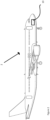
- the controller 10 carries out the method 30 illustrated in Figure 3 .
- the method 30 comprises monitoring 32 the airspeed of the aircraft 2, monitoring 34 the commanded rotation rate of the aircraft 2, and monitoring 36 the state of compression of the nose landing gear 6 of the aircraft.
- the airspeed of the aircraft 2 is compared to a speed threshold
- the commanded rotation rate of the aircraft 2 is compared to a rotation threshold
- the state of compression of the nose landing gear 6 is compared to a compression threshold.
- a warning is triggered, which may be for alerting the pilot of the early rotation of the aircraft 2.
- the step of monitoring 32 the airspeed of the aircraft may be carried out by monitoring the airspeed indicated by a pitot tube or similar as is commonly used on an aircraft 2.
- the controller 10 may monitor the airspeed determined by the avionics system of the aircraft 2, which may be determined based on comparing the values from multiple pitot tubes or similar to provide redundancy.
- the airspeed of the aircraft 2 may be determined by calculation.
- the wind velocity might be an approximate value based on the average or predicted wind speed at the airport, or might be that measured at a weather data source.
- the ground velocity of the aircraft might be measured using a satellite navigation system; by monitoring the speed of the aircraft across the runway; or by using an inertial reference system.
- the speed threshold is preferably V R , calculated by the pilots based on the usual factors such as the weight of the aircraft, cargo, passengers and fuel, the air temperature and pressure and so on. This may be determined by the pilots before takeoff and programmed in to the controller 10 or another system within the aircraft 2.
- the speed threshold may be offset from V R in order to avoid false alarms due to fluctuations in the monitored speed.
- the speed threshold may be predetermined for that aircraft type as a minimum likely V R .
- the step of monitoring 34 the commanded rotation rate of the aircraft 2 may be carried out by monitoring the control inputs made by the pilot. For example, the angle of or pressure exerted on the control column, side stick or equivalent may be monitored.
- the control inputs made by a pilot may be altered by a control system in order to generate appropriate control outputs for sending to the control surfaces (or effectors coupled thereto) of the aircraft.
- the commanded rotation rate of the aircraft may be determined by monitoring one or more of such control outputs.
- the commanded rotation rate of the aircraft 2 may be monitored by measuring the position of a control surface of the aircraft, such as an elevator, canard or other similar control surface that can be deflected to bring about a change of pitch of the aircraft.
- the rotation threshold may be simply set at a predetermined value, for example 1 degrees per second, or a value between 0.5 and 3 degrees per second.
- the rotation threshold may vary based on the runway the aircraft 2 is to take off from.
- the rotation threshold may be determined based on the proximity to the runway of any obstructions near the airport. If there are no such obstructions, the rotation threshold may be lower due to the absence of the aircraft needing to promptly reach a particular altitude for obstacle avoidance.
- the rotation threshold may vary based on the airspeed of the aircraft, being very low at low airspeeds and increasing as the aircraft approaches V R .
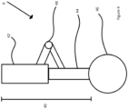
- a typical aircraft nose landing gear 6 comprises a compressible oleo-pneumatic strut 40, comprising an upper strut 42 that receives a lower strut 44 in a telescoping fashion.
- One or more wheels 46 is attached at the bottom of lower strut 44.
- the landing gear 6 further comprises a torque link, 48, coupled to the upper strut 42 and the lower strut 44 for preventing or limiting rotation between them around their common axis.
- the torque link 48 is hinged so as to permit the telescoping action of the compressible strut 40.
- compressible strut 40 When the weight of the aircraft 2 is partially supported by the nose landing gear 6, compressible strut 40 is compressed, with lower strut 44 being partially received within the upper strut 42. After takeoff, the weight of the lower strut 44 and wheel 46 naturally causes the compressible strut 40 to extend fully such that the compressible strut 40 is not compressed.
- Instrumentation can be provided on the landing gear 6 to measure the length of the compressible strut 40 and thereby derive the state of compression of the nose landing gear 6.
- this could be achieved, for example measuring the pressure within the compressible oleo-pneumatic strut 40, or the amount of the lower strut 44 that is received within the upper strut 42.
- the distance between the wheel 46 or lower strut 42 and the body of aircraft 2 could be measured using laser or radio range finding or similar.
- the relative angles of the members of the torque link 48 could be measured to determine the length of the compressible strut 40.
- Many of these techniques could also be adapted for use on a nose landing gear 6 that does not feature an oleo-pneumatic strut as the compressible member 40 but instead features another compressible member such as a compressible resilient member.
- the state of compression of the nose landing gear 6 could be inferred by measuring the distance between the nose of the aircraft 2 and the runway, for example using a laser or radio range finder. Further alternatively this distance could be measured with respect to the altitude of the nose of the aircraft 2, for example using a conventional or radar altimeter.
- a warning is triggered at block 40.
- the warning may take the form of an audible signal such as a buzzer or alarm.
- a visual warning such as an illuminated warning light or notification on a display.
- vibration of the controls could be used to warn the pilot of the early rotation of the aircraft.
- the controller 10 may instruct an inhibition in the positive pitch response of the aircraft to avoid further rotation of the aircraft. This could be by reducing the responsiveness of the pitch controls in the pitch up direction, or by adding an offset to the pitch inputs provided by the pilot.
- the software may be provided as machine readable instructions on a data carrier to cause operation of a controller 10 of the aircraft 2 to perform the method 30.
- the data carrier may be any appropriate data carrier having a memory capable of storing the machine readable instructions.
- the data carrier may be embedded in the aircraft 2 in use.
- any aircraft that rotates during a takeoff run may benefit from the invention, including light aircraft, cargo aircraft, and autogyro aircraft.
Landscapes
- Engineering & Computer Science (AREA)
- Aviation & Aerospace Engineering (AREA)
- Mechanical Engineering (AREA)
- Physics & Mathematics (AREA)
- General Physics & Mathematics (AREA)
- Traffic Control Systems (AREA)
Applications Claiming Priority (1)
| Application Number | Priority Date | Filing Date | Title |
|---|---|---|---|
| IN202121055404 | 2021-11-30 |
Publications (1)
| Publication Number | Publication Date |
|---|---|
| EP4190701A1 true EP4190701A1 (fr) | 2023-06-07 |
Family
ID=84361226
Family Applications (1)
| Application Number | Title | Priority Date | Filing Date |
|---|---|---|---|
| EP22208820.5A Withdrawn EP4190701A1 (fr) | 2021-11-30 | 2022-11-22 | Avertissement de rotation |
Country Status (2)
| Country | Link |
|---|---|
| US (1) | US20230166860A1 (fr) |
| EP (1) | EP4190701A1 (fr) |
Citations (5)
| Publication number | Priority date | Publication date | Assignee | Title |
|---|---|---|---|---|
| US3295369A (en) * | 1963-04-19 | 1967-01-03 | Elliott Brothers London Ltd | Aircraft take-off systems |
| US3435674A (en) * | 1966-07-29 | 1969-04-01 | Elliott Brothers London Ltd | Take-off director systems for aircraft |
| US20040200930A1 (en) * | 2003-04-11 | 2004-10-14 | Bays-Muchmore C. Byram | Multi-positional tail skids and associated methods of use |
| US20060284008A1 (en) * | 2005-03-29 | 2006-12-21 | Nance C K | Aircraft landing gear initial touch-down velocity monitor |
| US20210405658A1 (en) * | 2020-06-25 | 2021-12-30 | Embraer S.A. | Longitudinal trim control movement during takeoff rotation |
Family Cites Families (4)
| Publication number | Priority date | Publication date | Assignee | Title |
|---|---|---|---|---|
| US10202204B1 (en) * | 2016-03-25 | 2019-02-12 | AAR Aerospace Consulting, LLC | Aircraft-runway total energy measurement, monitoring, managing, safety, and control system and method |
| US11226639B2 (en) * | 2016-09-23 | 2022-01-18 | Yaborã Indústria Aeronáutica S.A. | Enhanced take-off system |
| US10696418B2 (en) * | 2018-06-05 | 2020-06-30 | Honeywell International Inc. | Method and system for representation of flight events using icons within a graphical user interface |
| WO2022192607A1 (fr) * | 2021-03-10 | 2022-09-15 | Zsm Holdings Llc | Conceptions d'aéronef cargo à aile fixe de faible densité pour le transport non flottant fermé d'éléments d'éolienne |
-
2022
- 2022-11-22 EP EP22208820.5A patent/EP4190701A1/fr not_active Withdrawn
- 2022-11-29 US US18/071,146 patent/US20230166860A1/en not_active Abandoned
Patent Citations (5)
| Publication number | Priority date | Publication date | Assignee | Title |
|---|---|---|---|---|
| US3295369A (en) * | 1963-04-19 | 1967-01-03 | Elliott Brothers London Ltd | Aircraft take-off systems |
| US3435674A (en) * | 1966-07-29 | 1969-04-01 | Elliott Brothers London Ltd | Take-off director systems for aircraft |
| US20040200930A1 (en) * | 2003-04-11 | 2004-10-14 | Bays-Muchmore C. Byram | Multi-positional tail skids and associated methods of use |
| US20060284008A1 (en) * | 2005-03-29 | 2006-12-21 | Nance C K | Aircraft landing gear initial touch-down velocity monitor |
| US20210405658A1 (en) * | 2020-06-25 | 2021-12-30 | Embraer S.A. | Longitudinal trim control movement during takeoff rotation |
Also Published As
| Publication number | Publication date |
|---|---|
| US20230166860A1 (en) | 2023-06-01 |
Similar Documents
| Publication | Publication Date | Title |
|---|---|---|
| EP3136197B1 (fr) | Système de protection de cabine d'aéronef | |
| CN109917812B (zh) | 高空高速无人机着陆接地状态控制方法 | |
| US6259379B1 (en) | Air-ground logic system and method for rotary wing aircraft | |
| EP3480117B1 (fr) | Protection/avertissement de décrochage d'aéronef ayant des réglages d'angle maximum d'attaque variables dans le temps pour les conditions de givrage | |
| US5225829A (en) | Independent low airspeed alert | |
| EP1235712B1 (fr) | Systeme evitant les cognements de queue d'un avion | |
| US20210403153A1 (en) | Multi mode safety system for vtol aircraft | |
| US7899620B2 (en) | Terrain avoidance method and system for an aircraft | |
| EP3453623A1 (fr) | Système de décollage sécurisé | |
| EP3521175B1 (fr) | Procédés et systèmes de contrôle de la poussée produite par une pluralité de moteurs sur un aéronef pour aider dans certaines conditions de vol | |
| US20100305784A1 (en) | Embedded Ground Proximity Warning System for Helicopters | |
| WO2011132291A1 (fr) | Dispositif de commande des conditions de vol pour un objet volant | |
| US8296054B2 (en) | Method and device for limiting the number of alarms generated by an anti-collision system on board an airplane | |
| US4769645A (en) | Excessive pitch attitude warning system for rotary wing aircraft | |
| CN111051921A (zh) | 用于基于感测到的空气移动控制飞机的系统和方法 | |
| US20200341492A1 (en) | Safe method and a safe system for controlling a position of an aircraft relative to the authorized flight envelope | |
| US11577853B2 (en) | Aircraft angle of attack and sideslip angle indicator | |
| KR20140094787A (ko) | 항공기의 운항 제어 방법 및 이러한 방법을 수행하는 장치 | |
| CN205113687U (zh) | 带有紧急制动装置的多旋翼无人飞行器 | |
| EP4190701A1 (fr) | Avertissement de rotation | |
| US8965603B2 (en) | Method and device for protecting an aircraft | |
| CN115258135A (zh) | 用于飞行器的失速保护方法、系统、存储介质及飞行器 | |
| JPH01309894A (ja) | 航空機の飛行経路角度制御装置 | |
| EP1727012B1 (fr) | Système pour éviter un toucher de queue pour un avion | |
| US20190278301A1 (en) | Flight control system |
Legal Events
| Date | Code | Title | Description |
|---|---|---|---|
| PUAI | Public reference made under article 153(3) epc to a published international application that has entered the european phase |
Free format text: ORIGINAL CODE: 0009012 |
|
| STAA | Information on the status of an ep patent application or granted ep patent |
Free format text: STATUS: THE APPLICATION HAS BEEN PUBLISHED |
|
| AK | Designated contracting states |
Kind code of ref document: A1 Designated state(s): AL AT BE BG CH CY CZ DE DK EE ES FI FR GB GR HR HU IE IS IT LI LT LU LV MC ME MK MT NL NO PL PT RO RS SE SI SK SM TR |
|
| STAA | Information on the status of an ep patent application or granted ep patent |
Free format text: STATUS: REQUEST FOR EXAMINATION WAS MADE |
|
| 17P | Request for examination filed |
Effective date: 20231108 |
|
| RBV | Designated contracting states (corrected) |
Designated state(s): AL AT BE BG CH CY CZ DE DK EE ES FI FR GB GR HR HU IE IS IT LI LT LU LV MC ME MK MT NL NO PL PT RO RS SE SI SK SM TR |
|
| GRAP | Despatch of communication of intention to grant a patent |
Free format text: ORIGINAL CODE: EPIDOSNIGR1 |
|
| STAA | Information on the status of an ep patent application or granted ep patent |
Free format text: STATUS: GRANT OF PATENT IS INTENDED |
|
| INTG | Intention to grant announced |
Effective date: 20240508 |
|
| STAA | Information on the status of an ep patent application or granted ep patent |
Free format text: STATUS: THE APPLICATION IS DEEMED TO BE WITHDRAWN |
|
| 18D | Application deemed to be withdrawn |
Effective date: 20240910 |