EP4190726A1 - Convoyeur capoté - Google Patents
Convoyeur capoté Download PDFInfo
- Publication number
- EP4190726A1 EP4190726A1 EP21853575.5A EP21853575A EP4190726A1 EP 4190726 A1 EP4190726 A1 EP 4190726A1 EP 21853575 A EP21853575 A EP 21853575A EP 4190726 A1 EP4190726 A1 EP 4190726A1
- Authority
- EP
- European Patent Office
- Prior art keywords
- bottom cover
- conveyor
- enclosed conveyor
- enclosed
- lower plate
- Prior art date
- Legal status (The legal status is an assumption and is not a legal conclusion. Google has not performed a legal analysis and makes no representation as to the accuracy of the status listed.)
- Withdrawn
Links
Images



Classifications
-
- B—PERFORMING OPERATIONS; TRANSPORTING
- B65—CONVEYING; PACKING; STORING; HANDLING THIN OR FILAMENTARY MATERIAL
- B65G—TRANSPORT OR STORAGE DEVICES, e.g. CONVEYORS FOR LOADING OR TIPPING, SHOP CONVEYOR SYSTEMS OR PNEUMATIC TUBE CONVEYORS
- B65G21/00—Supporting or protective framework or housings for endless load-carriers or traction elements of belt or chain conveyors
- B65G21/08—Protective roofs or arch supports therefor
-
- B—PERFORMING OPERATIONS; TRANSPORTING
- B65—CONVEYING; PACKING; STORING; HANDLING THIN OR FILAMENTARY MATERIAL
- B65G—TRANSPORT OR STORAGE DEVICES, e.g. CONVEYORS FOR LOADING OR TIPPING, SHOP CONVEYOR SYSTEMS OR PNEUMATIC TUBE CONVEYORS
- B65G15/00—Conveyors having endless load-conveying surfaces, i.e. belts and like continuous members, to which tractive effort is transmitted by means other than endless driving elements of similar configuration
- B65G15/60—Arrangements for supporting or guiding belts, e.g. by fluid jets
- B65G15/62—Guides for sliding belts
-
- B—PERFORMING OPERATIONS; TRANSPORTING
- B65—CONVEYING; PACKING; STORING; HANDLING THIN OR FILAMENTARY MATERIAL
- B65G—TRANSPORT OR STORAGE DEVICES, e.g. CONVEYORS FOR LOADING OR TIPPING, SHOP CONVEYOR SYSTEMS OR PNEUMATIC TUBE CONVEYORS
- B65G23/00—Driving gear for endless conveyors; Belt- or chain-tensioning arrangements
- B65G23/44—Belt or chain tensioning arrangements
-
- B—PERFORMING OPERATIONS; TRANSPORTING
- B65—CONVEYING; PACKING; STORING; HANDLING THIN OR FILAMENTARY MATERIAL
- B65G—TRANSPORT OR STORAGE DEVICES, e.g. CONVEYORS FOR LOADING OR TIPPING, SHOP CONVEYOR SYSTEMS OR PNEUMATIC TUBE CONVEYORS
- B65G39/00—Rollers, e.g. drive rollers, or arrangements thereof incorporated in roller-ways or other types of mechanical conveyors
- B65G39/10—Arrangements of rollers
Definitions
- the lower plate comprises a number of oblong holes in the longitudinal direction of the conventional enclosed conveyor, which enable a certain freedom for the movement of the coating plates in the longitudinal direction.
- Each oblong hole of the lower plate cooperates with a respective hole provided in a coating plate, in such a way to allow a bolt to be inserted and fixed by means of a self-locking nut.
- the self-locking nut must have a specific torque, being that it cannot be excessively of insufficiently tightened, for the coating plate to have the possibility to perform the expected movement due to the thermal expansion differences between said coating plate and the lower plate of the conventional enclosed conveyor.
- the gaps generated by the expansion of said bottom cover is also decreased when it is mounted to the lower plate of the enclosed conveyor, so as to prevent the malfunctioning of said enclosed conveyor.
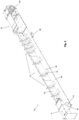
- the enclosed conveyor (10) comprises a conveyor belt (40) intended to carry a product to be transported in a manner already known in the state-of-the-art.
- the conveyor belt (40) is assembled inside the enclosed conveyor (10) so as to involve both the traction roller (111) of the traction module (11), and the return roller (131) of the return module (13), being said traction roller (111) responsible for running said conveyor belt (40) by activating the traction motor.
- the conveyor belt (40) operates in a counterclockwise rotation direction, on which the conveying portion (41) of said conveyor belt (40) moves towards the traction roller (111) and the return portion (42) of said conveyor belt (40) moves towards the return roller (131).
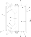
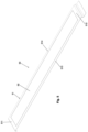
- the bottom cover (50) presents a substantially rectangular shape which extends throughout the longitudinal direction of the enclosed conveyor (10).
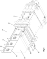
- Figure 5 presents the bottom cover (50) along with a representation of the peripheral region (51) and of an inner region (52).
- the bottom cover (50) also comprises an inner region (52) defined as an internal superficial area of the bottom cover (50) adjacent to the peripheral region (51).
- the inner region (52) is surrounded by the peripheral region (51), more specifically, the said inner region (52) is surrounded by the longitudinal ends (511, 512) and by the side edges (513, 514). It is noted that the inner region (52) is the area over which the return portion (42) of the conveyor belt (40) is more in contact with the bottom cover (50) when compared with the peripheral region (51).
- the bottom cover (50) of the proposed enclosed conveyor (10) is fixed only by the peripheral region (51), so as to make the bottom cover fixation process faster and more practical due to the lower quantity of fixation points which need to the duly tightened.
- the bottom cover (50) As proposed by this invention, it is possible to remove the bottom cover (50) without disassembling the entire enclosed conveyor (10) as already explained above. So, the bottom cover (50) replacement operation is much faster and much less demanding in comparison with the operation to replace all the coating plates (102) of the conventional enclosed conveyor (100).
- the enclosure (20) of the enclosed conveyor (10) comprises two side walls (21, 22).
- a first side wall (21) is mounted to one of the sides of the lower plate (23), while a second side wall (22) is arranged with the opposed side of said lower plate (23).
- the side walls (21, 22) are mounted with the lower plate (23) by means of a bolted joint.
- the upper plate (24) is also bolted on the side walls (21, 22).
- each intermediate module (12) of the enclosed conveyor (10) comprises two horizontal conveyor rollers (30) longitudinally spaced over said intermediate module (12), each conveyor roller (30) presenting an end mounted in the first side wall (21) and the opposed end mounted in the second side wall (22).
- each conveyor roller (30) cooperates with a first and a second inclined rollers (31, 32), being the first inclined roller (31) mounted in the first side wall (21) and the second inclined roller (32) mounted in the second side wall (22).
- a first and a second inclined rollers (31, 32) being the first inclined roller (31) mounted in the first side wall (21) and the second inclined roller (32) mounted in the second side wall (22).
- the bottom cover (50) is made of a material similar to that of the conveyor belt (40), such as, for example, fabric fibers wrapped with rubber with additive intended to reduce the friction coefficient, enabling the friction reduction between the lower plate of the enclosure (20) and the return portion (42) of the conveyor belt (40).
- a belt for the bottom cover (50) it is possible to manufacture said bottom belt (50) with a longitudinal length desired for its correct assembly to the proposed enclosed conveyor (10).
- the bottom cover (50) can be comprised by commercially available belts for other purposes and which are provided with compounds intended to improve the abrasion resistance and with low friction properties.
- the bottom cover (50) is fixed to the enclosed conveyor (10) only through two longitudinal ends (511, 512) of the peripheral region (51).
- the fixation points of the bottom cover (50) are arranged only in the longitudinal ends (511, 512) of the said bottom cover (50).
- the bottom cover (50) could be fixed to the traction module (11) only through the first longitudinal end (511), while the second longitudinal end (512) would remain free in the return module (13).
- the bottom cover (50) would remain stretched due to the friction with the said conveyor belt (40).
- the bottom cover (50) could be fixed to the return module (13) only through the second longitudinal end (512), while the first longitudinal end (511) would remain free in the traction module (11).
- the bottom cover (50) would remain stretched due to the friction with the said conveyor belt (40).
- the fixation of at least one of the longitudinal ends (511 or 512) of the bottom cover (50) to the said enclosed conveyor (10) is conducted from a static fixation point (61), the said static fixation point (61) being able to prevent a longitudinal displacement of the said bottom cover (50).
- the fixation of at least one of the longitudinal ends (511 or 512) of the bottom cover (50) is conducted from an adjustable fixation point (62), being the said adjustable fastening point (62) able to restrict the free longitudinal movement of said bottom cover (50) and to compensate the longitudinal deformation caused by the friction.
- the adjustable fastening point (62) also allows an adjustment of the bottom cover (50) strainby stretching or loosening of the said bottom cover (50).
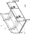
- the fixation of the first longitudinal end (511) of the bottom cover (50) to the enclosed conveyor (10) is conducted from a static fastening point (61), as it can be seen in Figure 7 .
- the static fastening point (61) is comprised by a fastening beam (611) mounted over a transversal extension (232) of the lower plate (23) of the enclosed conveyor (10) by means of fastening elements (612) such as, for example, pass-through bolts and self-locking nuts.
- the transversal extension (232) is a portion of the end of the lower plate (23) of the enclosed conveyor (10) which is substantially transversal with respect to the rest of the said lower plate (23), and that the fastening beam (611) presses the first longitudinal end (511) of the bottom cover (50) against the inner surface (231) of the said transversal extension (232) by tightening the fastening elements (612).
- the bottom cover (50) is fixed to the enclosed conveyor (10) only through part of the peripheral region (51) of the said bottom cover (50), more specifically, only through the first longitudinal end (511).
- the lower plate (23) of the enclosure (20) comprises a slot through which the second longitudinal end (52) of the said bottom cover (50) passes outside said enclosure (20) and among the stretching rollers (621).
- the stretching rollers (621) guarantee that the bottom cover (50) has its surface stretched, in such a way to enable the stretching beam (623) to be duly mounted in the second longitudinal end (512).
- the end of the intermediate module (12) which connects to the return module (13) of the enclosed conveyor (10) comprises a tab (121) on which it is possible to mount the pair of stretching screw spindles (622) across said tab (121).
- the stretching screw spindles (622) can cooperate with the stretching beam (623) mounted in the second longitudinal end (52) of the bottom cover (50) by means of a joint with bolts and self-locking nuts.
- the stretching beam (623) extends along the entire bottom cover (50) width and is conformed with a shape which allows the alignment of the stretching force exercised by the stretching screw spindles (622) with said bottom cover (50).
- the stretching screw spindles (622) there will be no undesirable deformations in said bottom cover (50).
- any of the longitudinal ends (511, 512) of the bottom cover (50) can be fixed to the enclosed conveyor (10) by means of a static fastening point (61) or by means of an adjustable fastening point (62) depending only of identifying its need for a certain application.
- the slot through which the second longitudinal end (512) of the bottom cover (50) passes out of the enclosure (20) of the enclosed conveyor (10) comprises a sealing system able to prevent the product transported by the conveyor belt (40) from leaving the inner part of said enclosed conveyor (10).
- the bottom cover (50) is fixed to the enclosed conveyor (10) only by the side edges (513, 514).
- the fixation points of the bottom cover (50) are arranged only in the side edges (513, 514) of said bottom cover (50).
Landscapes
- Engineering & Computer Science (AREA)
- Mechanical Engineering (AREA)
- Structure Of Belt Conveyors (AREA)
Applications Claiming Priority (2)
| Application Number | Priority Date | Filing Date | Title |
|---|---|---|---|
| BR102020015783-3A BR102020015783A2 (pt) | 2020-08-03 | 2020-08-03 | Transportador enclausurado |
| PCT/BR2021/050320 WO2022027117A1 (fr) | 2020-08-03 | 2021-07-30 | Convoyeur capoté |
Publications (2)
| Publication Number | Publication Date |
|---|---|
| EP4190726A1 true EP4190726A1 (fr) | 2023-06-07 |
| EP4190726A4 EP4190726A4 (fr) | 2024-08-07 |
Family
ID=80118863
Family Applications (1)
| Application Number | Title | Priority Date | Filing Date |
|---|---|---|---|
| EP21853575.5A Withdrawn EP4190726A4 (fr) | 2020-08-03 | 2021-07-30 | Convoyeur capoté |
Country Status (4)
| Country | Link |
|---|---|
| US (1) | US20230331492A1 (fr) |
| EP (1) | EP4190726A4 (fr) |
| BR (1) | BR102020015783A2 (fr) |
| WO (1) | WO2022027117A1 (fr) |
Families Citing this family (3)
| Publication number | Priority date | Publication date | Assignee | Title |
|---|---|---|---|---|
| CA3148634A1 (fr) * | 2021-02-12 | 2022-08-12 | Berry Global, Inc. | Emballage de bobine de film |
| FR3132704B1 (fr) * | 2022-02-15 | 2024-01-12 | Sg2C | Convoyeur interposable entre un convoyeur d’entrée et un convoyeur de sortie et installation de convoyage comprenant un tel convoyeur |
| KR102945614B1 (ko) * | 2025-07-04 | 2026-04-01 | 우영균 | 밀폐형 벨트 컨베이어 |
Family Cites Families (16)
| Publication number | Priority date | Publication date | Assignee | Title |
|---|---|---|---|---|
| US4183430A (en) * | 1977-08-25 | 1980-01-15 | Hunter Mfg., Inc. | Grain handling flight conveyor assembly |
| US4215776A (en) * | 1977-11-10 | 1980-08-05 | Joseph M. Stofan | Belt conveyor idler |
| JPS6036924U (ja) * | 1983-08-23 | 1985-03-14 | 石川島播磨重工業株式会社 | ベルトコンベヤ用インパクト装置 |
| US6044965C1 (en) * | 1998-02-18 | 2013-03-05 | Philip G Clark | Troughing idlers for belt conveyors |
| CA2229941A1 (fr) * | 1998-02-19 | 1999-08-19 | Philip G. Clark | Convoyeur a courroie a plancher de transport double |
| JP2000142956A (ja) * | 1998-11-04 | 2000-05-23 | Ishikawajima Harima Heavy Ind Co Ltd | 落粉清掃装置 |
| US6360879B1 (en) * | 2000-02-24 | 2002-03-26 | George N. Crawford | Low profile belt conveyor |
| US6913138B2 (en) * | 2003-04-30 | 2005-07-05 | Daniel Wiggins | Load bearing assembly for a conveying belt and a method of assembling the load bearing assembly |
| JP5314003B2 (ja) * | 2008-03-18 | 2013-10-16 | トーヨーカネツソリューションズ株式会社 | ベルトコンベヤ及びベルトコンベヤ装置 |
| KR101039714B1 (ko) * | 2009-04-13 | 2011-06-08 | 주식회사 신성플랜트 | 사행방지기구가 구비된 컨베이어장치 |
| US8225926B1 (en) * | 2011-02-18 | 2012-07-24 | Enduro Systems, Inc. | Troughing side idler for belt conveyors |
| CN202296107U (zh) * | 2011-10-22 | 2012-07-04 | 广东摩德娜科技股份有限公司 | 一种带有全封闭防尘罩的皮带输送机 |
| WO2018232449A1 (fr) * | 2017-06-21 | 2018-12-27 | Beinoni Pty Ltd | Unité de suspension pour bande transporteuse |
| BR102019004398A2 (pt) | 2018-03-15 | 2020-09-29 | Tmsa - Tecnologia Em Movimentação S.A. | Transportador enclausurado |
| BR102018071790A2 (pt) * | 2018-10-23 | 2020-05-05 | Tmsa - Tecnologia Em Movimentação S.A. | transportador enclausurado |
| CN117401360B (zh) * | 2023-10-19 | 2025-12-02 | 三一重型装备有限公司 | 转载机凸槽及转载机 |
-
2020
- 2020-08-03 BR BR102020015783-3A patent/BR102020015783A2/pt not_active Application Discontinuation
-
2021
- 2021-07-30 WO PCT/BR2021/050320 patent/WO2022027117A1/fr not_active Ceased
- 2021-07-30 EP EP21853575.5A patent/EP4190726A4/fr not_active Withdrawn
- 2021-07-30 US US18/019,332 patent/US20230331492A1/en not_active Abandoned
Also Published As
| Publication number | Publication date |
|---|---|
| EP4190726A4 (fr) | 2024-08-07 |
| BR102020015783A2 (pt) | 2022-02-15 |
| US20230331492A1 (en) | 2023-10-19 |
| WO2022027117A1 (fr) | 2022-02-10 |
Similar Documents
| Publication | Publication Date | Title |
|---|---|---|
| EP4190726A1 (fr) | Convoyeur capoté | |
| US8322519B2 (en) | Belt conveyor | |
| EP1506125B1 (fr) | Unite d'entrainement a moteur pour dispositif de transport et systeme de transport associe | |
| US6820734B1 (en) | Conveyor belt cleaner tensioning device | |
| US5320036A (en) | Continuously operating material press | |
| CA3066022A1 (fr) | Arrangement d'entrainement, element d'entrainement et mecanisme d'entrainement pour chariot de transport | |
| CA2202977A1 (fr) | Absorbeur de chocs pour bande transporteuse | |
| US4248341A (en) | Roller conveyor and its track | |
| Velmurugan et al. | Conveyor belt troubles (bulk material handling) | |
| US7571803B2 (en) | Bearing unit for a conveying installation for the transport of goods by way of a conveyor belt | |
| JP2004504235A (ja) | コンベヤ・ノーズバー | |
| KR200471774Y1 (ko) | 상품운반장치 | |
| SE509724C2 (sv) | Kontinuerligt arbetande press för pressning av pressgodsmattor och pressgodsbanor vid tillverkning av spånskivor, fiberskivor, laminatskivor och dylikt | |
| US20210380345A1 (en) | Enclosed conveyor | |
| US20160137420A1 (en) | An Improved Liner | |
| US6918238B2 (en) | Preloadable, externally installable and removable bearing and shaft assembly | |
| Gurjar | Failure analysis of belt conveyor system | |
| CN118683908B (zh) | 一种抗静电耐腐蚀型输送带 | |
| JP3194337B2 (ja) | 急傾斜コンベヤ設備 | |
| US6829987B2 (en) | Belt-type particleboard press | |
| US6648042B2 (en) | Load-applying device for a double facer | |
| TWI839065B (zh) | 輥軋機、冷軋方法和鋼板製造方法 | |
| KR950009035Y1 (ko) | 벨트 컨베이어의 리턴롤러 위치조정 브래킷 | |
| AU5540198A (en) | Belt conveyor with lined trunking floor | |
| RU48952U1 (ru) | Натяжное устройство транспортирующей ленты |
Legal Events
| Date | Code | Title | Description |
|---|---|---|---|
| STAA | Information on the status of an ep patent application or granted ep patent |
Free format text: STATUS: THE INTERNATIONAL PUBLICATION HAS BEEN MADE |
|
| PUAI | Public reference made under article 153(3) epc to a published international application that has entered the european phase |
Free format text: ORIGINAL CODE: 0009012 |
|
| STAA | Information on the status of an ep patent application or granted ep patent |
Free format text: STATUS: REQUEST FOR EXAMINATION WAS MADE |
|
| 17P | Request for examination filed |
Effective date: 20230222 |
|
| AK | Designated contracting states |
Kind code of ref document: A1 Designated state(s): AL AT BE BG CH CY CZ DE DK EE ES FI FR GB GR HR HU IE IS IT LI LT LU LV MC MK MT NL NO PL PT RO RS SE SI SK SM TR |
|
| DAV | Request for validation of the european patent (deleted) | ||
| DAX | Request for extension of the european patent (deleted) | ||
| A4 | Supplementary search report drawn up and despatched |
Effective date: 20240708 |
|
| RIC1 | Information provided on ipc code assigned before grant |
Ipc: B65G 39/10 20060101ALI20240702BHEP Ipc: B65G 15/62 20060101ALI20240702BHEP Ipc: B65G 21/08 20060101AFI20240702BHEP |
|
| STAA | Information on the status of an ep patent application or granted ep patent |
Free format text: STATUS: THE APPLICATION IS DEEMED TO BE WITHDRAWN |
|
| 18D | Application deemed to be withdrawn |
Effective date: 20250128 |